Cylindrical gear geometry
Requirements
The following basic requirements apply for gear units used in drive technology applications:
A gearbox transmits power and motion. It also usually converts torque and speed via a gear ratio.
It should transmit power and motion as uniformly as possible to keep vibrational excitation low.
High power density (e.g., torque per kg) ensures cost efficiency.
The power transmission should be efficient.
The components used should be simple and suitable for mass production.
High operational safety.
Cylindrical gears are typically used for drives with parallel axes as they meet these requirements to a high degree.
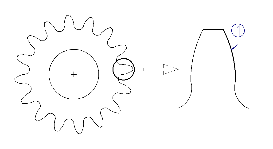
(1) Involute
Involute cylindrical gears
The involute tooth shape is responsible for the advantageous properties of cylindrical gears. This can be explained by the so-called thread design, in which the involute results from the unwinding of a thread from a cylinder.
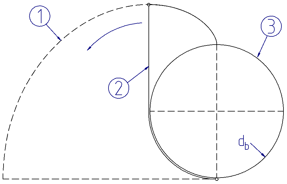
Involute thread design
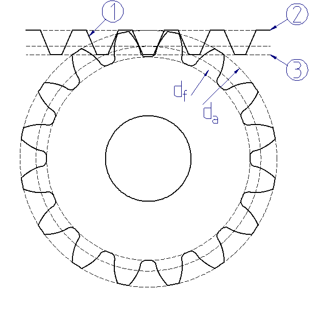
(1) Involute
(2) Thread
(3) Base circle
The tooth flanks of involute gears are created in much the same way: a gear cutting tool with a slanted cutting edge (pressure angle α > 0) is rolled along the pitch circle to generate the involute tooth flank. The base circle, at which the contact normal is tangent to the flank, results from the pitch circle multiplied by the cosine of the pressure angle.
Several of these involutes are combined, evenly spaced according to the number of teeth, to achieve a complete gear.
Figure 14. Utilized area of the involute 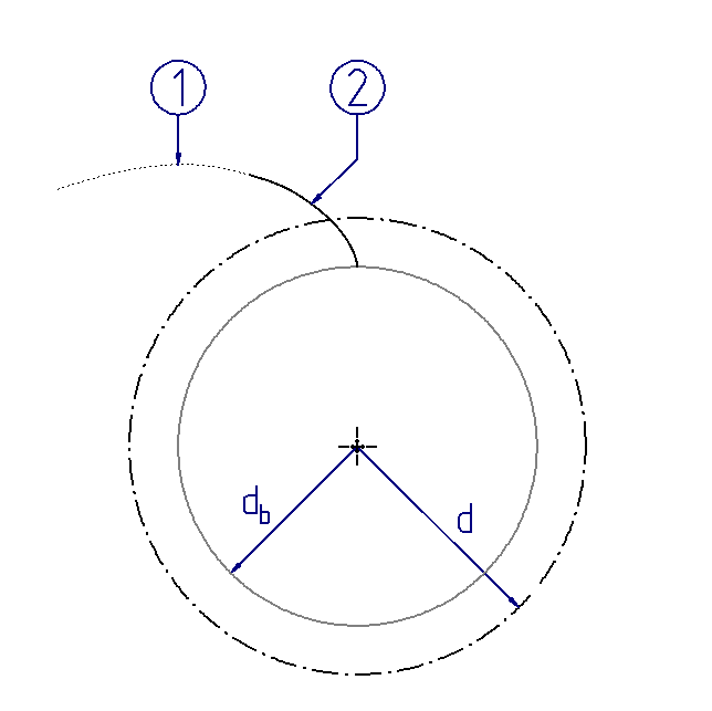 Utilized area of the involute = tooth flank (1) Involute (2) Utilized area of the involute | Figure 15. Additional flanks 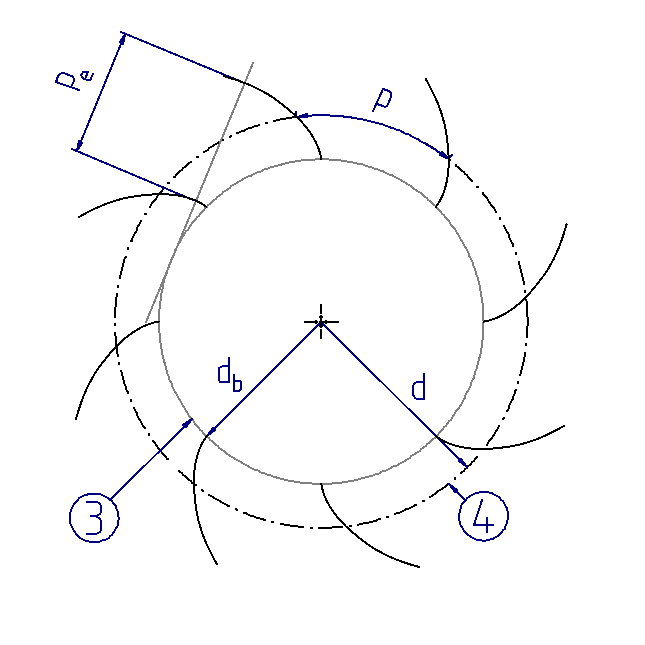 Number of flanks z Module m = d/z Pitch p = m*pi Base pitch pe (3) Base circle db (4) Reference circle d | Figure 16. Rear flanks 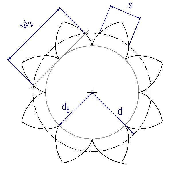 Tooth thickness s Base tangent length W |
Different numbers of teeth can be distributed across the circumference, depending on their size. The so-called normal module (mn), which is defined as the pitch circle divided by the number of teeth, is used to measure the size of the teeth. The number of teeth and the module determine the basic size of a gear. For the tooth shape to remain as independent of the number of teeth as possible, gear data such as the tooth depth are often specified relative to the module.
Transverse module
Normal module
The advantages of involute gears are a result of the design properties described above, which correspond to the gear requirements:
Cylindrical gears transmit torque via form fit, and thus have a high power density, low friction, and therefore high efficiency and operational reliability.
The contact normal of the involute is always tangent to the base circle along the path of contact. Therefore, the normal of the tooth force is fixed, and always points in the direction of the path of contact for all meshing positions. Thus, no vibration excitation results from the geometry and kinematics of an involute gear (without consideration of the elastic tooth deformations under load). This also applies to changes to the center distance due to tolerances or deformations.
The kinematics of the rolling movement can be mechanically modeled in the manufacturing process. This allows for relatively simple manufacturing with a high level of precision. Gears with different numbers of teeth can be manufactured using the same tool.
The geometry and kinematics can be described by simple formula relationships, so that reliable and standardized analyses of load carrying capacity are available.
Basic rack tooth profile
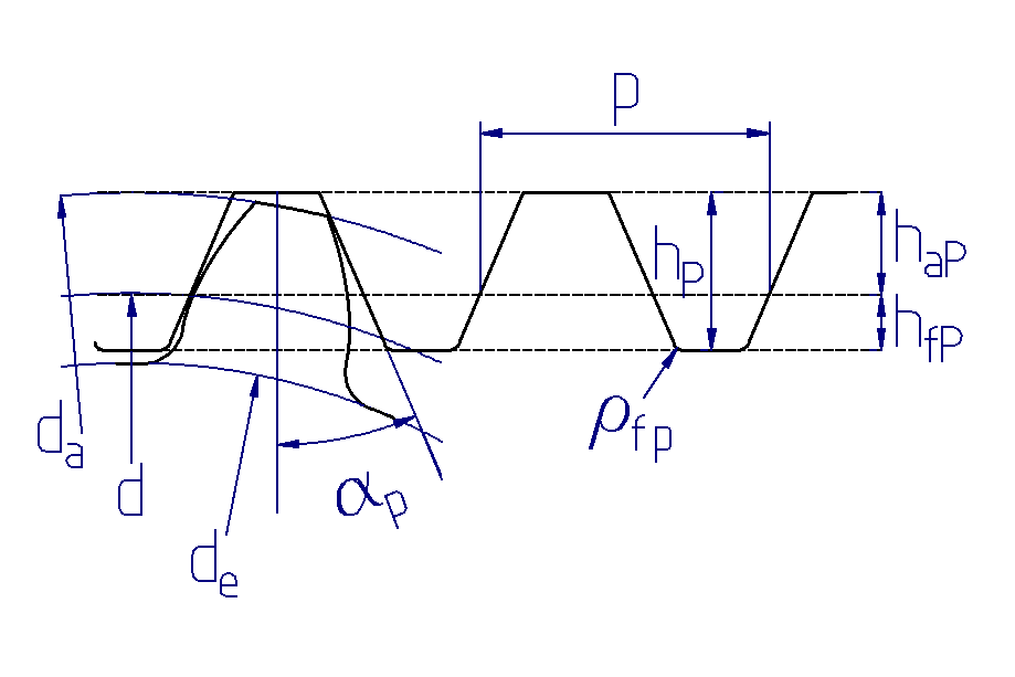
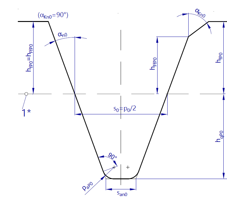
Manufacturing-relevant gear data is typically specified for the so-called basic profile, which corresponds to the rolling of a gear with an infinitely large diameter. The basic profile is therefore rack-shaped with straight flanks. The tip and root lines of the basic profile are tangent to the tip or root diameter of the gear, such that the tooth depth of the basic profile corresponds to the tooth depth of the gear. As with gears, the basic profile can be defined for a manufacturing tool. The basic profile of the manufacturing tool corresponds to the obverse of the gear cutting tool. It should be noted that the tooth tip of the basic profile of the gear corresponds to the tooth root of the basic profile of the tool, and vice versa.
(1) Basic profile
(2) Tip line
(3) Root line
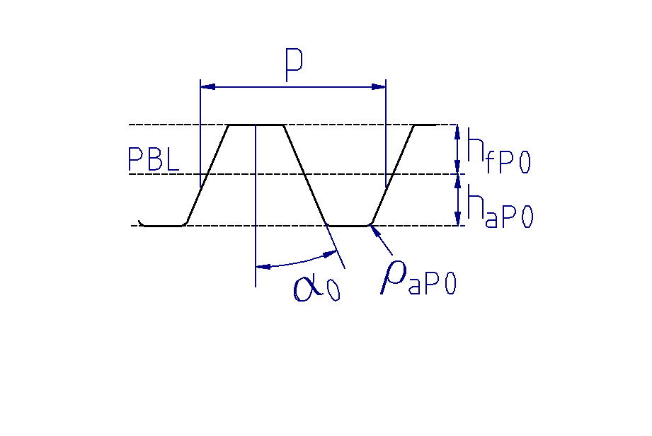
Basic profile of the gear |
Basic profile of the tool |
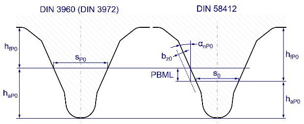
The basic profile is intended to minimize the number of gear cutting tools used while simultaneously providing a simpler definition of the geometric values via the straight flank profile. Basic profiles are standardized in DIN 867 for general mechanical engineering and in DIN 58400 for gears in precision engineering. Geometries deviating from these standards can also be defined in the FVA-Workbench.
Simulation of rolling contact
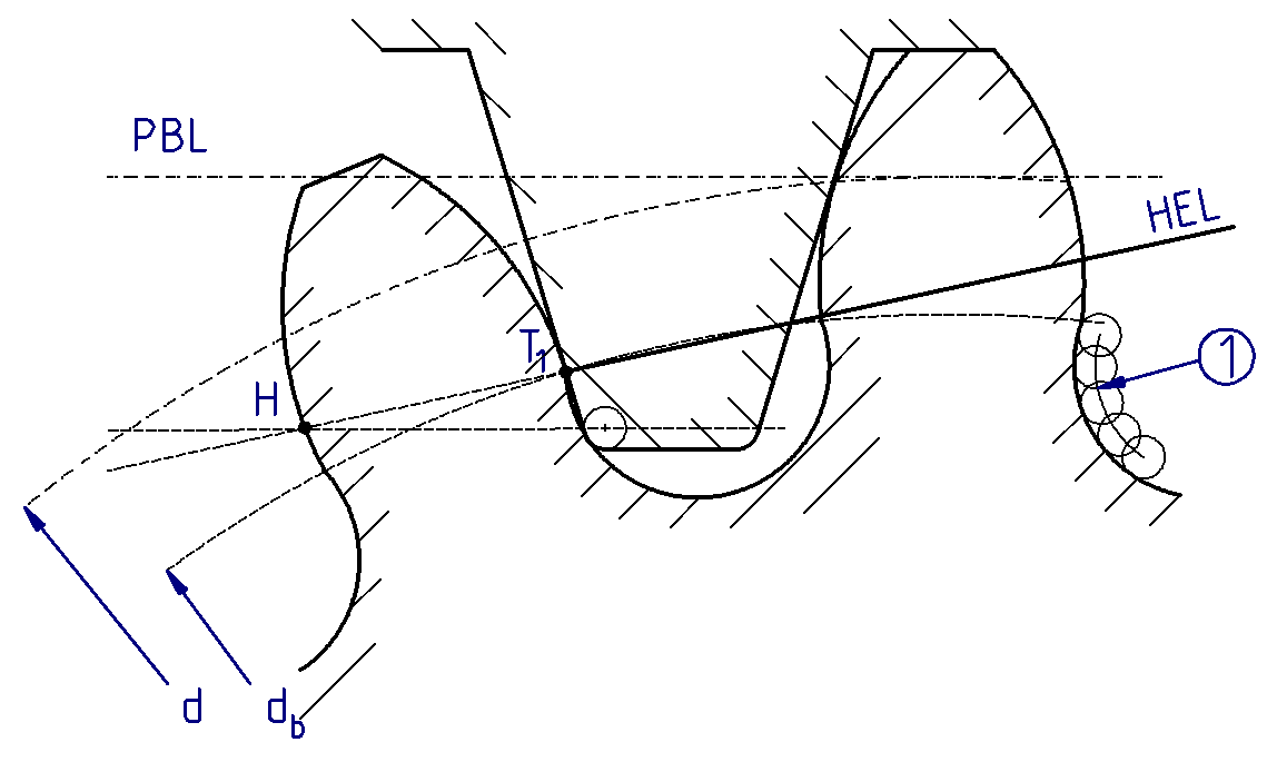
In the FVA-Workbench, the cylindrical gear geometry is determined based on the simulation of rolling contact with one or two specified gear cutting tools. This corresponds to the kinematics for generating an involute described above. A cut that is angled toward the pitch line is used for cylindrical gears. This still generates an involute, but the hobbing now takes place on the reference circle instead of the base circle. This results in a base circle diameter of:
Figure 17. Perpendicular cutting edge 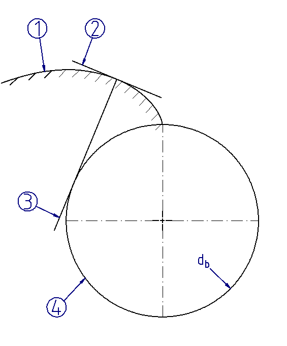 Perpendicular cutting edge | Figure 18. Angled cutting edge 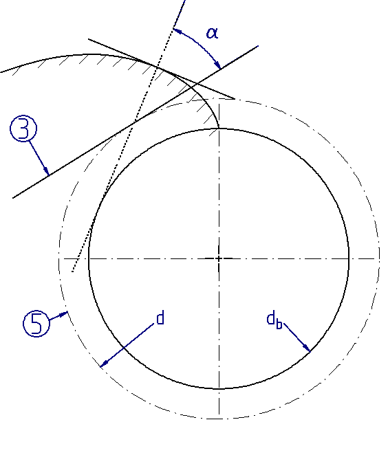 Angled cutting edge |
(1) Involute (2) Tool (3) Pitch line (4) Base circle db (5) Reference circle d |
Rolling kinematics during gear manufacturing
In the FVA-Workbench, straight-flanked tools (such as milling and rack-shaped cutters) or involute cutting wheels can be defined for both the preliminary and finished teeth according to DIN 3960.
 Straight-flanked tool with (left) and without (right) chamfer angle αKn0. | 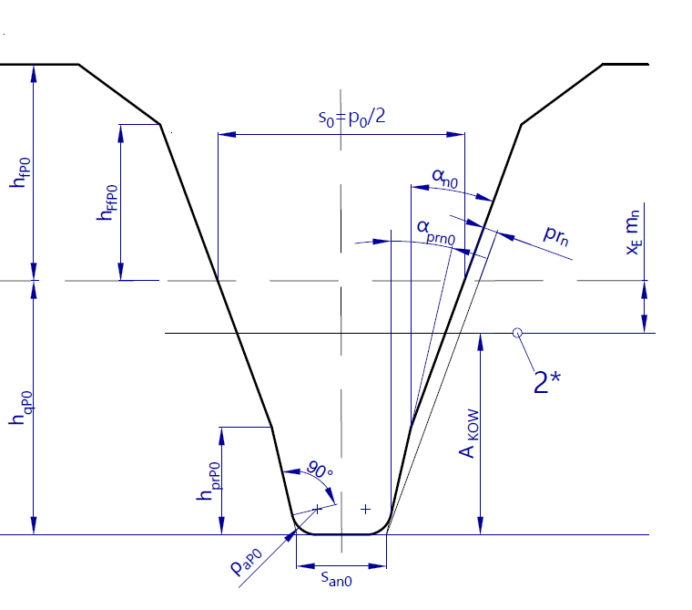 Straight-flanked tool with protuberance |
 Cutting wheel without flank and tip chamfer (left) Cutting wheel with flank and tip chamfer (right) | 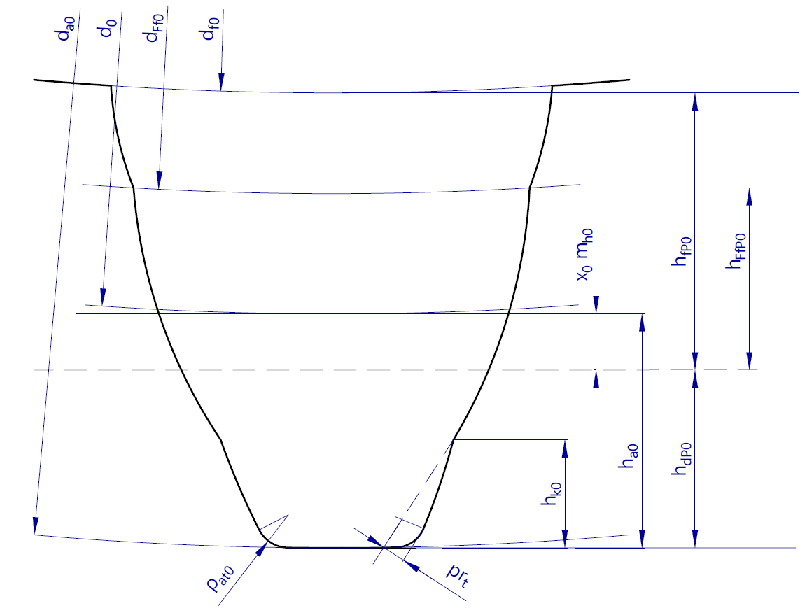 Cutting wheel with protuberance and tip radius |
Tools are defined by specifying basic profile data. As the basic profile of the gear cutting tool represents the obverse of the basic profile of the gear, it should be noted that the addendum of the basic profile of the tool corresponds to the dedendum of the associated gear, and vice versa. It is also possible to define a reference measuring line for the tool depths that deviates from the datum line.
Key parameters of the tool basic profile
The edge radius of the tool must be specified in addition to the tool depths. Automatic determination of a fully-rounded tool tip can also be selected.
Tool edge radius
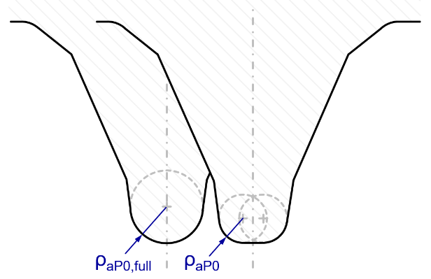
If a gear is manufactured by two hobbing processes, grinding abrasion from the finishing tool produces a notch in the tooth root. This can be prevented by specifying a protuberance for the preliminary tool. Widening the tool tip during roughing creates an undercut, which then ensures that the finishing tool does not come into contact with the tooth root fillet. If the protuberance amount is the same size as the grinding removal, the two effects cancel each other out.
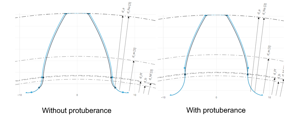
Tooth profile with and without protuberance tool
Tooth root fillet
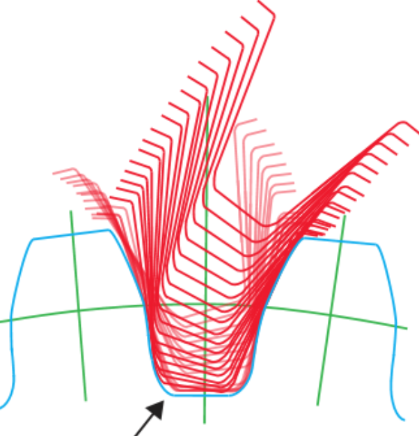
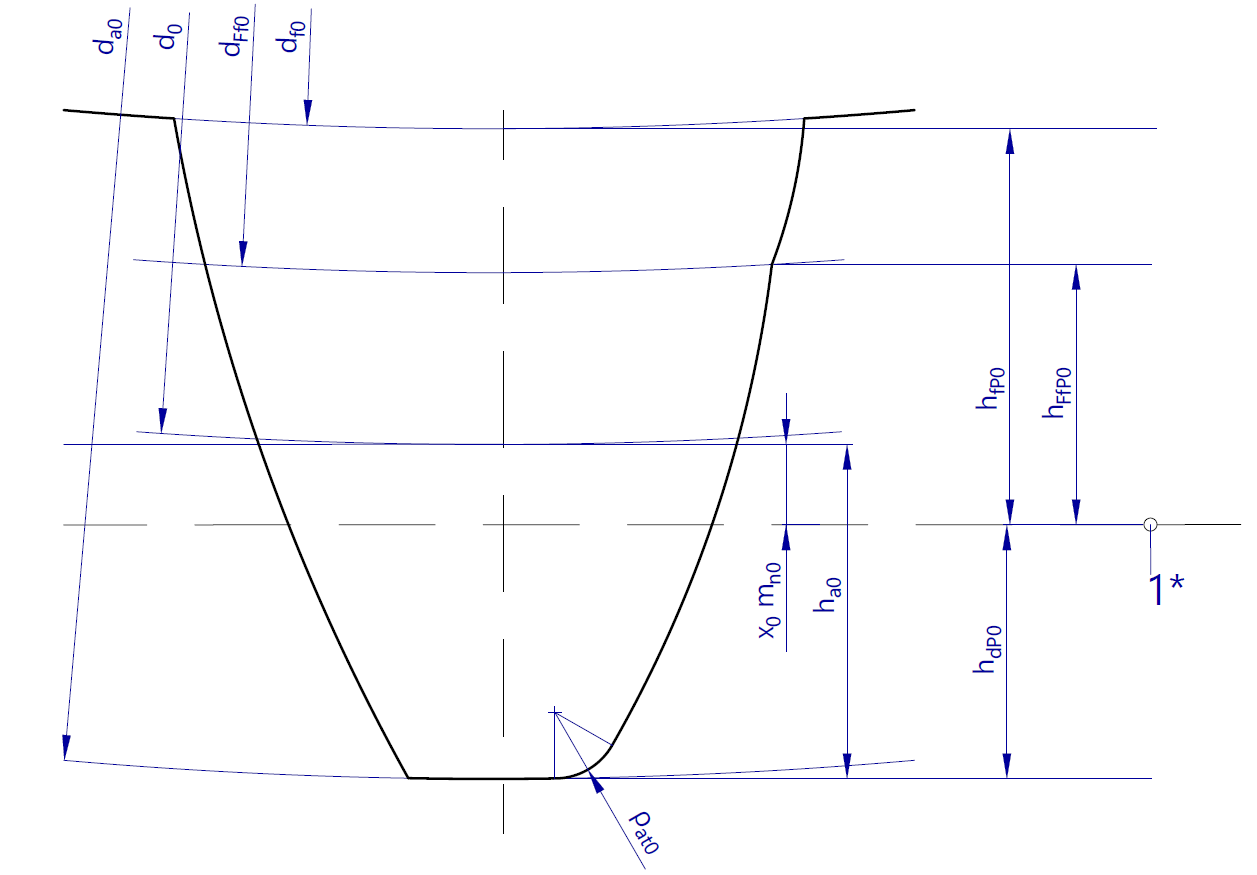
The tooth root fillet is generated by the tool head, which represents a so-called trochoid (grinding involute). For gears without an undercut, the tooth root fillet is tangential to the flank involute.
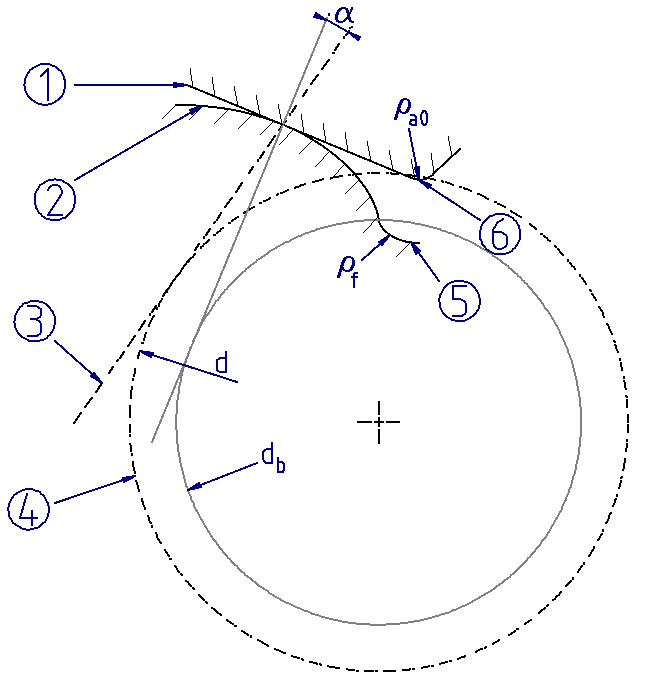
(1) Tool
(2) Involute
(3) Pitch line
(4) Reference circle
(5) Tooth root fillet
(6) Tool tip rounding
In the case of a very small number of teeth, extreme negative addendum modifications, or if a protuberance tool is used, an undercut is generated and there is no longer a tangential transition between the flank involute and the tooth root fillet. If this undercut is too large, it can lead to a reduction of the cross section of the tooth root, and therefore to weakening of the tooth root and a shortening of the involute.
(1) Path of the tool head
This can be remedied by reducing the depth of the tool head or via a positive addendum modification.
Addendum modification
Selection of the addendum modification defines the area of the involute which makes up the tooth flank. The profile reference line (to which the tool depths refer) is shifted by the amount of the addendum modification.
Figure 21. Positive addendum modification 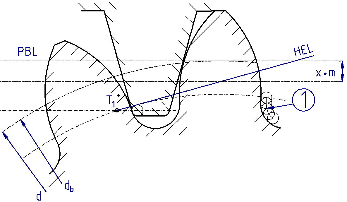 (1) Path of the tool head | Figure 22. Negative addendum modification |
With a positive addendum modification, the tool is shifted outward. This results in the following changes to the tooth form:
| With a negative addendum modification, the tool is shifted inward. This results in the following changes to the tooth form:
|
When the total addendum modification is specified in the FVA-Workbench, the addendum modifications can automatically be determined according to the following criteria:
Recommendation according to DIN 3992
Uniform tooth root stress
Uniform maximum sliding speeds
Uniform rolling contact pressure
In addition to these criteria, the addendum modifications can also be defined by specifying the following test dimensions:
Base tangent length and number of teeth measured
Diametral (two-ball) measurement and measurement ball diameter
Chordal tooth thickness and chordal height
Tip circle diameter
For cylindrical gears, the tip circle diameter is usually determined by the outer diameter of the workpiece to be machined; it is typically only machined directly by the gear cutting tool for gears with a small modulus. In addition to defining the tip circle via the tool and direct specification, the FVA-Workbench can also automatically determine the tip circle according to DIN 3960 or DIN 867, or by specifying an addendum coefficient. Generally speaking, a greater contact ratio can be achieved with a larger tip circle diameter; however, this is limited by the following criteria:
Minimum tooth thickness at the tooth tip sa. If the tooth tip thickness is too low, the reduced cross-section can lead to fracturing of the tooth tips. For surface-coated gears, it can also lead to overcuring, which further increases the risk of fracture.
Minimum tooth tip clearance. The distance between the tooth tip and the tip circle diameter of the mating gear must be kept as low as possible to avoid contact, even with unfavorable tolerances.
Meshing interference in the tooth root of the mating gear. Depending on the design of the tooth root of the mating gear, contact may also occur in the tooth root fillet above the root circle if the tip circle diameter is too large.
These conditions are checked in the FVA-Workbench, taking the specified tolerances and the load-dependent deformations of the gear system into account, and a corresponding warning is issued to the user.
Gear tooth quality
The permissible tolerances for cylindrical gears are determined by specifying the gear tooth quality. The corresponding variations are divided into the following groups:
Profile variations
Tooth trace variations
Tooth thickness variations
Pitch variations
Run-out variations
In the FVA-Workbench, these variations can be calculated and output based on their gear quality according to ISO 1328 (1995 and 2013) as well as DIN 3960.
Deviations and flank clearance
For most applications, it must be ensured that sufficient rear flank clearance is available to prohibit jamming of the gearing, even with unfavorable tolerances. This is achieved by defining suitable upper and lower base tangent length variations for manufacturing. In the FVA-Workbench, the deviation tolerance series specified in DIN 3967 can be used, or user-specified values can be entered. The minimum and maximum flank clearance then arises from the base tangent length variations in combination with the center distance tolerance. The center distance dimensions can be entered directly or determined by specifying the degree of tolerance for the tolerance zone according to DIN 3964. The system also checks how the center distance and the flank clearance are affected by elastic deformations in the gear. If the backlash is reduced to zero, a warning is displayed.
Test dimensions
In practice, it is important that the manufactured gears also comply with the calculation tolerances. This can be determined using the following testing methods, already mentioned in the definition of the addendum modification:
Figure 23. Base tangent length 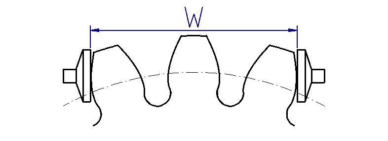 | Figure 24. Diametral measurement 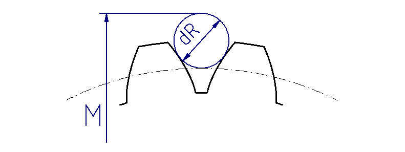 | Figure 25. Chordal tooth thickness 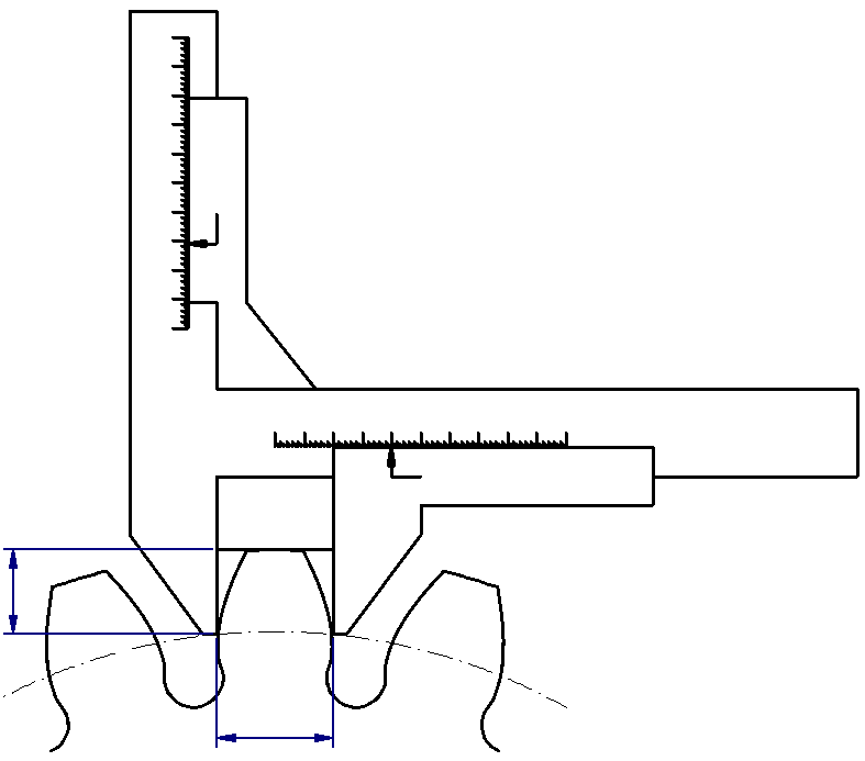 |
The FVA-Workbench automatically calculates and outputs the permissible minimum and maximum values for the individual measurements based on the dimensions specified by the user. User-specified values for the measuring equipment that deviate from DIN 3960 can also be used. The number of teeth measured for the base tangent length and the diameter of the measuring element for the diametral mass can be adjusted by the user.
Although the measured value for the tooth thickness is determined directly, this method is often imprecise. The tolerance for the tip circle diameter, which determines the height of the measuring position on the profile, is often relatively rough.