Power loss

Power losses and efficiency calculation in the FVA-Workbench
Symbol | Description | Unit |
|---|---|---|
PV | Total power loss | W |
PVZP | Load-dependent gear losses | W |
PVZ0 | Load-independent gear losses | W |
PVLP | Load-dependent rolling bearing losses | W |
PVL0 | Load-independent rolling bearing losses | W |
PVPB | Plain bearing losses | W |
PVD | Sealing losses | W |
PVST | Rim or planet carrier losses | W |
PVX | Other losses | W |
Power losses caused by tooth and bearing friction can be divided into load-dependent (index 0) and load-independent (index P) power losses.
Seals, bearings, and gears have a negative effect on the overall efficiency due to rolling and sliding friction, even without load.
The following table lists the different calculation approaches for various components, including the corresponding methods/sources.
Type of loss | Components | Method/source |
|---|---|---|
PVZP | Cylindrical gears | Hv according to OHLENDORF, TALBOOM, WIMMER µmZ according to SCHLENK, DOLESCHEL |
PVZP | Bevel and hypoid gears | HV and µmZ according to WECH |
PVZP | Worm stages | DIN 3996, FVA 729 I |
PVZ0 | Cylindrical gears, bevel and hypoid gears | Splash lubrication: Squeeze and splash losses according to MAUZ, WALTER Injection lubrication: Squeeze losses according to MAUZ, BUTSCH Pulse losses according to ARIURA, BUTSCH Ventilation losses according to MAURER |
PVLP,PVL0 | Rolling bearings | SKF, SCHAEFFLER, TIMKEN, ISO14179-2 |
PVPB | Plain bearings | COMBROS R&A |
PVD | Seals | ISO 14179-1, ISO 14179-2, LINKE |
PVST | Planet carriers | KETTLER |
Table: Power loss calculations, methods, sources
The losses are considered in the system calculation. Torque losses are subtracted from the transferred torque at the position in the power flow at which they occur. The speed remains unaffected; the losses do not have a braking or slowing effect on the overall system.
The efficiency of the gearbox is calculated from the ratio of useable power to applied power.
Symbol | Description | Unit |
|---|---|---|
η | Efficiency | % |
PAn | Input power | W |
PV | Total power loss | W |
Gear losses
The power loss of the gears is calculated from the load-dependent and load-independent loss components. The calculation differentiates between cylindrical gears, bevel and hypoid gears, and worm gears.
Load-dependent gear losses for cylindrical gears
The load-dependent gear losses are determined using the following basic equation, based on Coulomb friction.
Symbol | Description | Unit |
|---|---|---|
PVZP | Load-dependent gear losses | W |
HV | Tooth loss factor | - |
µmZ | Average gear friction coefficient | - |
PAn | Input power | W |
There are different methods for calculating the tooth loss factor and average gear friction coefficient. These are described in more detail below.
The tooth loss factor according to OHLENDORF is very often used to evaluate the efficiency of the geometric design of a gear. The method shown here corresponds to the generally accepted extension according to Wimmer.
Symbol | Description | Unit |
|---|---|---|
HV | Tooth loss factor | - |
u | Gear ratio (z2/z1) | - |
z1/2 | Number of teeth of pinion/wheel | - |
βb | Base circle helix angle | deg |
ε1/2 | Tip contact ratio of pinion/wheel | - |
a0…4 | Coefficients for tooth loss factor | - |
With coefficients for the tooth loss factor from:
Transverse contact ratio | Location of the pitch point C | a 0 | a 1 | a 2 | a 3 | a 4 |
|---|---|---|---|---|---|---|
0 ≤ εα ≤ 1 | before the engagement area | 0 | 0 | 0 | 1/εα | 1/εα |
in the engagement area | 0 | 0 | 0 | 1/εα | 1/εα | |
after the engagement area | 0 | 0 | 0 | 1/εα | 1/εα | |
1 < εα ≤ 2 | before the engagement area | 0 | 1 | 1 | 0 | 0 |
in the first double engagement area | 0 | 1 | -1 | 0 | 1 | |
in the engagement area | 1 | -1 | -1 | 1 | 1 | |
in the second double engagement area | 0 | -1 | 1 | 1 | 0 | |
after the engagement area | 0 | 1 | 1 | 0 | 0 | |
2 < εα ≤3 | before the engagement area | 0 | 1 | 1 | 0 | 0 |
in the first triple engagement area | 0 | 1 | -1 | 0 | 2/3 | |
in the first double engagement area | 4/3 | -1/3 | -1 | 1/3 | 2/3 | |
in the second triple engagement area | 1 | -1/3 | -1/3 | 1/3 | 1/3 | |
in the second double engagement area | 4/3 | -1 | -1/3 | 2/3 | 1/3 | |
in the third triple engagement area | 0 | -1 | 1 | 2/3 | 0 | |
after the engagement area | 0 | 1 | 1 | 0 | 0 |
The TALBOOM method is a ZF company standard.
This formula is applicable when the first gear is the driving gear; otherwise, the tip contact ratios in the formula are changed to the other gear, accordingly.
Symbol | Description | Unit |
|---|---|---|
HV | Tooth loss factor | - |
z1/2 | Number of teeth of pinion/wheel | - |
βb | Base circle helix angle | deg |
ε1/2 | Tip contact ratio of pinion/wheel | - |
εα | Transverse contact ratio | - |
The local-geometric tooth loss factor according to WIMMER considers the actual load distribution, including gear modifications. Efficiency is improved when the load is shifted in the direction of the pitch point in tooth contact. As a result, this method can be used for efficiency-oriented gear design.
In the Ohlendorf calculation, the tooth contact is only considered on the path of contact, and a simplified formula is derived based on assumptions. The basic equation is:
The Wimmer calculation also considers the contact width, and the tooth loss factor is calculated using numerical methods without simplifications. The starting point is the following equation:
Symbol | Description | Unit |
|---|---|---|
HV | Tooth loss factor | - |
pet | Base pitch at base circle | mm |
x | Coordinates on the path of contact: distance from the pitch point | mm |
A,E | Coordinates on the path of contact: beginning and end of the path of contact | mm |
FN | Normal force of the tooth | N |
vg | Sliding speed | m/s |
y | Coordinate on the path of contact | mm |
b | Face width of the contact | mm |
Fbt | Peripheral force at pitch circle | N |
vtb | Circumferential speed at base circle | m/s |
The SCHLENK method is most commonly used for calculating the average gear friction coefficient. Only a few input variables are required.
Symbol | Description | Unit |
|---|---|---|
µmZ | Average tooth friction coefficient | - |
Fbt | Peripheral force at pitch circle | N |
vΣC | Sum of speeds at pitch point | m/s |
ρredC | Equivalent radius of curvature at pitch point | mm |
ηOil | Dynamic operating oil viscosity | mPas |
XL | Lubricant factor | - |
Ra | Arithmetic mean roughness value of the gear partners 0.5 · (Ra1 + Ra2) | µm |
b | Face width | mm |
The DOLESCHEL method is more accurate than the simple SCHLENK method for determining the average gear friction coefficient. However, it requires specific test rig reference measurements that are often not available in practice.
with
and
with
if
or
where
Symbol | Description | Unit |
|---|---|---|
µmZ | Average tooth friction coefficient | - |
ξ | Amount of EHD friction for mixed friction | - |
µF,ref | Solid friction coefficient (under reference conditions) | - |
µEHD,ref | EHD friction coefficient (under reference conditions) | - |
pH,ref | Hertzian contact stress (under reference conditions) | MPa |
vΣ,ref | Sum of speeds (under reference conditions) | m/s |
ηOil,ref | Dynamic operating oil viscosity (under reference conditions) | mPas |
αEHD/F | Exponent for pressure influence | - |
βΣ,EHD/F | Exponent for sum of speeds influence | - |
γEHD | Exponent for viscosity influence | - |
h0 | Minimum lubricating film thickness | µm |
Ra | Arithmetic mean roughness value of the gear partners 0.5 · (Ra1 + Ra2) | µm |
These 11 test rig reference measurements must be specified for the lubricant in the database.
Load-dependent gear losses for bevel/hypoid gears
The load-dependent gear losses of bevel and hypoid gears are managed similar to cylindrical gears. The WECH calculation method is used. This method approximates bevel and hypoid gears as virtual crossed helical gears according to Niemann/Winter.
The gear losses are calculated from the average friction coefficient, the tooth loss factor, and the input power:
Symbol | Description | Unit |
PVZP | Load-dependent gear losses | W |
µmZ | Average gear friction coefficient | - |
HV | Tooth loss factor | - |
PAn | Input power | W |
The following factors have an influence on the average friction coefficient µmZ:
The load, average total sliding speed, and the average sum of speeds of the virtual crossed helical gear and the equivalent radius of curvature at the pitch point are considered via the load and geometry factor QH.
The lubricant characteristics VL, type of lubrication VS, operating oil viscosity VZ, and roughness of the tooth flanks VR are included as factors.
Symbol | Description | Unit |
µmZ | Average gear friction coefficient | - |
VR | Roughness factor | - |
VS | Lubrication factor | - |
VZ | Viscosity factor | - |
VL | Lubricant factor | - |
QH | Load and geometry factor | - |
Symbol | Description | Unit |
QH | Load and geometry factor | - |
FN | Normal force of the virtual gear | N |
βb2 | Helix angle at base circle of gear | deg |
b2 | Face width of gear | m |
Kgm | Sliding factor | - |
ρn | Equivalent radius of curvature | m |
vΣm | Mean sum of velocity | m/s |
If it is already known (for example, either internally confirmed or from tests), the coefficient of friction can also be specified as an input value instead of calculated according to WECH.
The tooth loss factor HV is also calculated according to WECH for the virtual crossed helical gears, and considers its load sharing and speed course over the path of contact. The calculation is finally performed by integrating the speed course over the path of contact.
For more detailed information on the calculation, refer to the Wech dissertation (in German):
WECH, L.: Untersuchungen zum Wirkungsgrad von Kegelrad- und Hypoidgetrieben, TU München, Diss., 1987
Load-dependent gear losses for worm gear stages
The load-dependent gear losses of worm gear stages are calculated according to DIN 3996.
For the driving worm gear:
with
For the driven worm gear:
with
Symbol | Description | Unit |
PVZP | Load-dependent gear losses | W |
PAn | Input power | W |
ηZ | Gear efficiency | - |
γm | Reference lead angle | deg |
µmZ | Average gear friction coefficient | - |
There are different methods for calculating the average gear friction coefficient. They are described in more detail below.
Calculation of the average gear friction coefficient according to the Oehler dissertation (2018) was integrated into the 2019 revision of DIN 3996. Part of the work for this dissertation was performed within FVA Research Project 729 I, and is documented in the final report (2017).
The average gear friction coefficient is calculated as follows:
Symbol | Description | Unit |
µmZ | Average gear friction coefficient | - |
µGr | Boundary friction coefficient | - |
µFl | Liquid friction coefficient | - |
Ψ | Solid load bearing amount | - |
The boundary friction coefficient depends on the type of base oil, the average flank pressure, as well as the material of the worm and worm gear.
The solid load bearing amount depends on the average minimum lubrication gap thickness, the surface topography of the worm and gear flanks, and their materials.
The liquid friction coefficient is calculated from the average shear stress in the lubrication gap, average flank pressure, and the solid load bearing amount.
Even though the standard is no longer valid, the average gear friction coefficient can still be calculated according to DIN 3996:2012 for comparison purposes.
The associated formula is as follows:
Symbol | Description | Unit |
µmZ | Average gear friction coefficient | - |
µ0T | Basic friction coefficient | - |
YS | Size factor | - |
YG | Geometry factor | - |
YW | Material factor | - |
YR | Roughness factor | - |
Load-independent gear losses for cylindrical, bevel, and hypoid gears
No-load gear losses include splash, squeeze, ventilation, and pulse losses. These losses are speed-dependent but not load-dependent. Load-independent gear losses are typically much smaller than load-dependent gear losses.
Load-independent gear losses can be calculated according to various methods, depending on the type of lubrication and the circumferential speed.
Immersion lubrication
Squeeze and splash losses are considered with immersion lubrication.
Symbol | Description | Unit |
PVZ0,tauch | Load-independent gear losses with immersion lubrication | W |
PVZ0,quetsch | Squeeze losses: squeezing out of excess oil in the tooth contact | W |
PVZ0,plansch | Splash losses: splashing of the gears in the oil | W |
Whether the squeeze and splash losses should be determined according to MAUZ or WALTER can be specified individually for all cylindrical gear stages. The default is calculation according to MAUZ. Detailed warnings will be issued if the validity range of the MAUZ or WALTER calculation equations are exceeded; however, the calculation will continue if possible.
The entire hydraulic torque losses (i.e., the sum of the squeeze and splash torque losses) are transferred to the pinion or wheel shaft, depending on the load path.
Transferred to the pinion shaft:
Transferred to the wheel shaft:
Symbol | Description | Unit |
TVZ0,tauch | Load-independent gear torque loss with immersion lubrication | Nm |
TVZ0,quetsch | Squeeze torque losses | Nm |
TVZ0,plansch,Ritzel/Rad | Splash torque loss of the pinion/wheel | Nm |
KP1G | Correction factor for the simultaneously immersed mating gear | - |
z1/2 | Number of teeth of the pinion/wheel | - |
The power loss is calculated according to the reference shaft with the following formula:
Symbol | Description | Unit |
PVZ0,tauch | Load-independent gear losses with immersion lubrication | W |
TVZ0,tauch | Load-independent gear torque loss with immersion lubrication | Nm |
n | Shaft speed | 1/s |
Squeeze losses according to MAUZ
Different operating cases are considered in the squeeze losses according to MAUZ.
If both shafts are arranged horizontally and the immersed gear feeds the oil:
directly into the tooth mesh, case W1
indirectly into the tooth mesh via the wall of the casing, case W2
If the shafts are arranged vertically, the direction of rotation is inconsequential. This corresponds to cases S1 and S2.
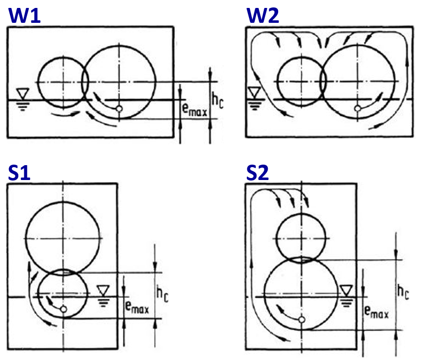 |
Figure: operating cases
The squeeze torque loss of the mesh is calculated as:
where
Operating case W1: CSp = e/hc
Operating case W2: CSp = 0
Operating cases S1 and S2: CSp = (e/hc)²
Symbol | Description | Unit |
TVZ0,quetsch | Squeeze torque loss | Nm |
ρOil | Oil density at operating temperature | kg/m³ |
b | Minimum face width of pinion and wheel | m |
rw | Radius at pitch circle of the deepest immersed gear | m |
vt | Circumferential speed at pitch circle | m/s |
CSp | Splash oil factor | - |
e | Immersion depth of the deepest immersed gear | mm |
hc | Height of the point of contact above the point of deepest immersion of the cylindrical gear stage |
Splash losses according to MAUZ
The splash torque losses are calculated separately at the pinion and gear, with a correction factor to compensate for the reciprocal influence of the gears.
Symbol | Description | Unit |
TVZ0,plansch | Splash torque loss | Nm |
νOil | Kinematic viscosity at operating temperature (ν0 = 1) | m²/s |
ra | Radius at tip circle (r0 = 1) | m |
CWZ | Wall distance factor, oil feed side | - |
CWA | Wall distance factor, oil outflow side | - |
CM | Module factor | - |
CV | Oil volume factor | - |
ρOil | Oil density at operating temperature | kg/m³ |
AB | Immersed wheel surface in operation | m² |
vt | Circumferential speed at pitch circle | m/s |
for srZ ≤ 1.3 and vt ≥ 10 m/s
for srZ > 1.3 or vt < 10 m/s
Symbol | Description | Unit |
CWZ | Wall distance factor, oil feed side | - |
srZ | Distance between the tip circle diameter and casing on the immersed side of the gear | m |
ra | Radius at tip circle (r0 = 1) | m |
vt | Circumferential speed at pitch circle (vt0 = 10) | m/s |
for srA ≤ 1.3 and vt ≥ 10 m/s
for srA > 1.3 or vt < 10 m/s
Symbol | Description | Unit |
CWA | Wall distance factor, oil outflow side | - |
srA | Distance between the tip circle diameter and the casing on the emerged side of the gear | m |
ra | Radius at tip circle | m |
vt | Circumferential speed at pitch circle (vt0 = 10) | m/s |
Symbol | Description | Unit |
CM | Module factor | - |
mn | Normal module (mn0 = 0.0045 · mn) | m |
for VG/VOil ≥ 2.5
where QV 0 = 0.74 · e-0.438
for VG/VOil < 2.5
Symbol | Description | Unit |
CV | Oil volume factor | - |
VG | Volume of the casing | m³ |
VOil | Oil volume in the casing | m³ |
QV0 | Factor for consideration of the immersion depth | - |
e | Immersion depth | m |
vt | Circumferential speed at pitch circle (vt0 = 10) | m/s |
where
for vt ≤ 30 m/s
for vt > 30 m/s
Symbol | Description | Unit |
AB | Immersed wheel surface in operation | m² |
ra | Radius at tip circle | m |
α | Opening angle of the immersed surface | deg |
b | Face width | m |
eB | Operating immersion depth | m |
e | Immersion depth | m |
vt | Circumferential speed at pitch circle | m/s |
mn | Normal module | m |
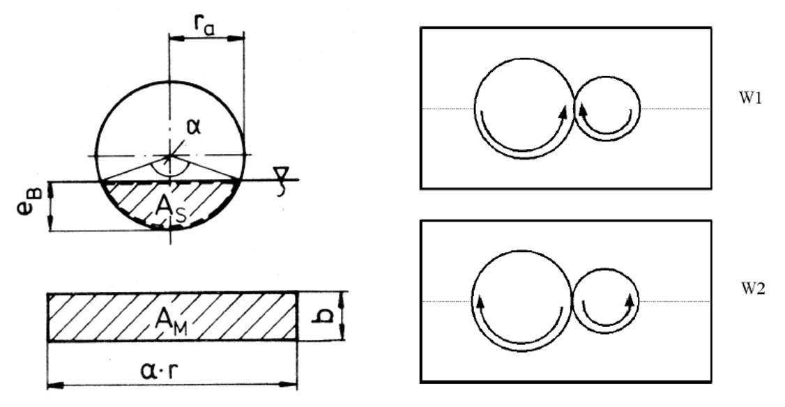 |
Figure: Immersed wheel surface in operation and operating conditions
for operating case W1, direct oil feed into the tooth mesh
for operating case W2, indirect oil feed into the tooth mesh via the wall of the casing
Symbol | Description | Unit |
KP1G | Correction factor for the simultaneously immersed mating gear | - |
vt | Circumferential speed at pitch circle (vt0 = 10) | m/s |
νOil | Kinematic viscosity at operating temperature (ν0 = 1) | m²/s |
b | Face width (b0 = 0.01) | m |
This calculation method was derived from tests. The limit values of the tests also constitute the validity range of the method. However, these limits are conservative and results outside this range may also be valid.
Influencing variable | Symbol | Unit | from | to |
Reynolds number | Re=(vt·ra)/ν | - | 4125 | 531428 |
Relative immersion depth | e/ra | - | 0.04 | 1.0 (2.0) |
Relative radial wall distance on the feed/outflow side | (srZ/rA)/ra | - | 0.03 | 3.15 |
Immersion depth relative to the height of the pitch point | e/hc | - | 0.02 | 1.0 |
Volume ratio | VG/VOil | - | 2.0 | 12.0 |
Gear ratio | u | - | 1.0 | 2.0 |
Tip circle radius | ra | mm | 66 | 124 |
Face width | b | mm | 10 | 60 |
Normal module | mn | mm | 3 | 6 |
Circumferential speed | vt | m/s | 10 | 60 |
Immersion depth | e | mm | 5 | 135 |
Kinematic oil viscosity | ν | mm²/s | 14 | 240 |
Density of the oil | ρ | kg/m³ | 855 | 881 |
Table: Validity range of the Mauz calculation equations
The total hydraulic torque loss corresponds to the sum of the squeeze and splash torque losses, and is relative to the pinion or wheel shaft, depending on the load path.
Relative to the pinion shaft:
Relative to the wheel shaft:
Symbol | Description | Unit |
TVZ0,tauch | Load-independent gear torque loss with splash lubrication | Nm |
TVZ0,quetsch | Squeeze torque loss | Nm |
TVZ0,plansch,Ritzel/Rad | Splash loss of pinion/wheel | Nm |
u | Gear ratio (z2/z1) | - |
The power loss is calculated according to the reference shaft with the following formula:
Symbol | Description | Unit |
PVZ0,tauch | Load-independent gear losses with splash lubrication | W |
TVZ0,tauch | Load-independent gear torque losses with splash lubrication | Nm |
n | Shaft speed | 1/s |
Squeeze losses according to WALTER
The squeeze torque loss of the gear mesh is calculated as follows:
for direct oil feed into the gear mesh
for indirect oil feed into the gear mesh via the wall of the casing
Symbol | Description | Unit |
TVZ0,quetsch | Squeeze torque loss | Nm |
CSp | Splash oil factor | - |
ρOil | Oil density at operating temperature | kg/m³ |
rw | Radius at pitch circle of the deepest immersed gear | m |
b | Minimum face width of pinion and wheel | m |
vt | Circumferential speed at pitch circle | m/s |
νOil | Kinematic viscosity at operating temperature (ν0 = 1) | m²/s |
e | Immersion depth of the deepest immersed gear | m |
hc | Height of the point of contact above the deepest immersed point of the cylindrical gear stage | m |
lh | Hydraulic length | m |
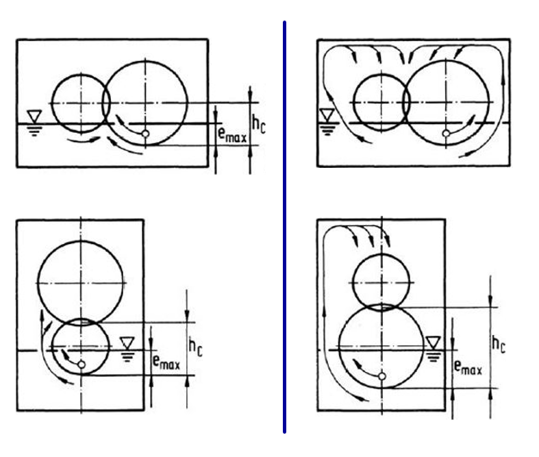 |
Figure: Direct oil feed into the gear mesh (left), indirect via the wall of the casing (right)
Splash losses according to WALTER
The splash torque losses are calculated separately for the pinion and gear.
Symbol | Description | Unit |
TVZ0,plansch | Splash torque loss | Nm |
CW | Wall distance factor | - |
CV | Oil volume factor | - |
CPL | Splash torque factor | - |
ρOil | Oil density at operating temperature | kg/m³ |
vt | Circumferential speed at pitch circle | m/s |
ra | Radius at tip circle | m |
b | Face width | m |
for srZ/(2 · ra) ≥ 1
for srZ/(2 · ra) < 1
Symbol | Description | Unit |
CW | Wall distance factor | - |
srZ | Distance between the tip circle diameter and casing at the immersing side of the gear | m |
ra | Radius at tip circle | m |
vt | Circumferential speed at pitch circle | m/s |
g | Gravitational constant | m³/(kg · s²) |
for VZ/VOil ≤ 0.1
for VZ/VOil > 0.1
Symbol | Description | Unit |
CV | Oil volume factor | - |
VZ | Volume of oil displaced by the gear | m³ |
VOil | Oil volume in the casing | m³ |
Symbol | Description | Unit |
CPL | Splash torque factor | - |
e | Immersion depth | m |
ra | Radius at tip circle | m |
b | Face width | m |
vt | Circumferential speed at pitch circle | m/s |
νOil | Kinematic viscosity at operating temperature | m²/s |
g | Gravitational constant | m³/(kg · s²) |
When CV = 1 and CW = 1, it results in the following simplified equation:
Symbol | Description | Unit |
TVZ0,plansch | Splash torque loss | Nm |
g | Gravitational constant | m³/(kg · s²) |
ρOil | Oil density at operating temperature | kg/m³ |
e | Immersion depth | m |
b | Face width | m |
ra | Radius at tip circle | m |
vt | Circumferential speed at pitch circle | m/s |
νOil | Kinematic viscosity at operating temperature | m²/s |
This calculation method was derived from tests. The limit values of the tests also constitute the validity range of the method. However, these limits are conservative and results outside this range may also be valid.
Influencing variable | Symbol | Unit | from | to |
Reynolds number | Re=(vt·ra)/ν | - | 7980 | 471429 |
Froude number | Fr=vt²/(g · ra) | - | 93 | 4645 |
Relative immersion depth | e/ra | - | 0.12 | 1.71 |
Relative width | b/ra | - | 0.09 | 0.63 |
Relative tooth depth | h/mn | - | 2.25 | - |
Relative radial wall distance on the feed side | srZ/(2ra) | - | 0.16 | 1.56 |
Relative oil volume | VZ/VOil | - | 0.01 | 0.20 |
Hydraulic length | lH=(4AG)/U | mm | 629 | 1332 |
Tip circle radius | ra | mm | 79 | 110 |
Face width | b | mm | 5 | 10 |
Normal module | mn | mm | 3 | 6 |
Circumferential speed | vt | m/s | 10 | 60 |
Kinematic oil viscosity | ν | mm²/s | 14 | 99 |
Density of the oil | ρ | kg/m³ | 850 | - |
Table: Validity range for the Walter calculation equations
Injection lubrication
For injection lubrication, the calculation method is automatically determined by the existing circumferential speed vt. Thus, for vt > 60 m/s, the squeeze and pulse losses are calculated according to BUTSCH; for vt < 60 m/s, the squeeze losses are calculated according to MAUZ and the pulse losses are calculated according to ARIURA. Detailed warnings are issued if the validity range of the BUTSCH squeeze loss calculation equations is left; however, the calculation continues if possible.
Symbol | Description | Unit |
PVZ0,einspritz | Load-independent gear losses with injection lubrication | W |
PVZ0,impuls | Pulse losses: flow deflection of an oil stream impacting the tooth flanks | W |
PVZ0,quetsch | Squeeze losses: squeezing out of excess oil in the tooth contact | W |
PVZ0,ventilation | Ventilation losses: turbulence of the injected oil | W |
Splash losses do not occur with injection lubrication, or are negligible and therefore not calculated.
Ventilation losses are calculated according to MAURER, as long as the calculation is not disabled.
For squeezing losses, a differentiation is made between injection at the beginning and end of the engagement.
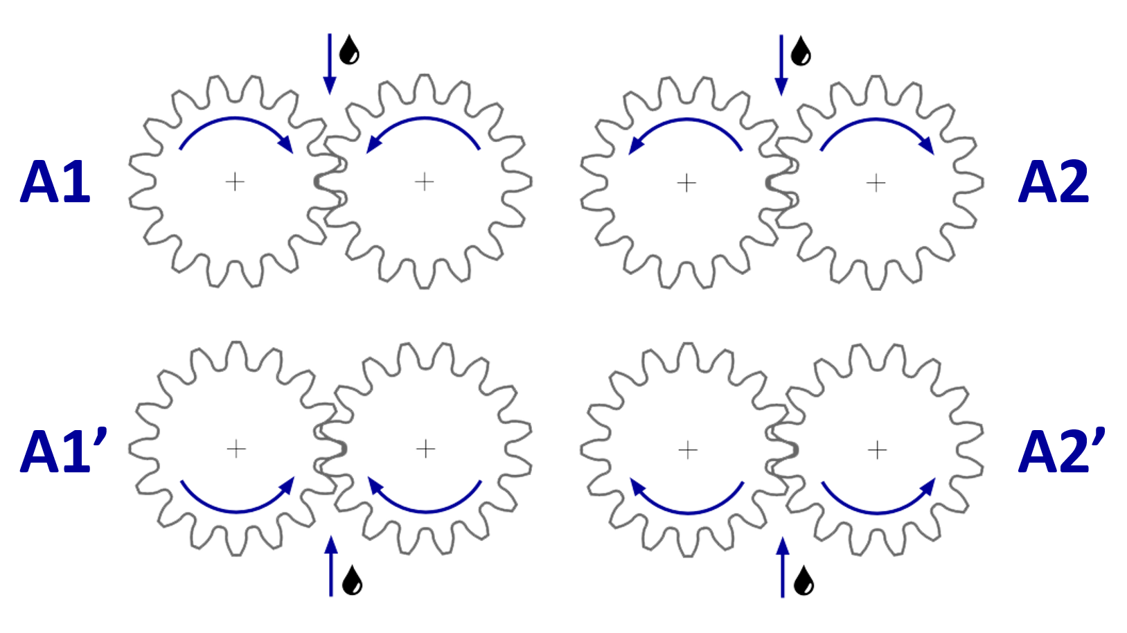 |
Figure: Injection variants
Injection at the beginning of the mesh (A1 and A1’) :
where C1 = 1 for injection variant A1
where C1 = 0.9 for injection variant A1‘
Injection at the end of the mesh (A2 and A2’) :
where C2 = 1 for injection variant A2
where C2 = 0.85 for injection variant A2‘
Symbol | Description | Unit |
TVQ | Squeeze torque loss | Nm |
C1/2 | Constants, depending on the injection variant | - |
ρOil | Oil density at operating temperature | kg/m³ |
Qe | Injected oil volume flow rate | m³/s |
rw | Radius at pitch circle | m |
vt | Circumferential speed at pitch circle | m/s |
vs | Injection speed | m/s |
b | Face width | m |
mn | Normal module | m |
νOil | Kinematic viscosity at operating temperature (ν0 = 1) | m²/s |
hZ | Working depth (hZ0 = 2.3 ·mn) | m |
MAUZ differentiates between injection at the beginning and end of the mesh. The following relative values are introduced for both cases:
Injection into the beginning of the mesh (A1) :
where
Injection into the end of the mesh (A2) :
where
Symbol | Description | Unit |
TVQ | Squeeze torque loss | Nm |
C3/4/5 | Constants, depending on the injection variant | - |
vt* | Relative dimensionless circumferential speed at pitch circle | - |
vt | Circumferential speed at pitch circle | m/s |
Qe* | Relative dimensionless injected oil volume flow | - |
Qe | Injected oil volume flow | m³/s |
b* | Relative dimensionless face width | - |
b | Face width | m |
r* | Relative dimensionless radius | - |
u | Gear ratio (z2/z1) | - |
The validity range for both injection variants is:
ISO VG oil viscosity 22 to 86
Face width 0.075 m ≤ b ≤ 0.125 m
Circumferential speed 60 m/s ≤ vt ≤ 200 m/s
Solid steam nozzles
Injection at the beginning of the mesh (A1 and A1‘):
Injection at the end of the mesh (A2 and A2‘):
where C1 = 1 for injection variant A1
where C1 = 0.9 for injection variant A1‘
where C1 = 1 for injection variant A2
where C1 = 0.85 for injection variant A2‘
Symbol | Description | Unit |
TVI | Pulse torque loss | Nm |
C1 | Constant, depending on the injection variant | - |
rw | Radius at pitch point | m |
ρOil | Oil density at operating temperature | kg/m³ |
Qe | Injected oil volume flow | m³/s |
vt | Circumferential speed at pitch circle | m/s |
vs | Injection speed | m/s |
If the injection speed drives the gears, this results in negative losses. In this case, the pulse losses are set to 0.
Injection into the beginning of the mesh (A1 and A1‘):
Injection into the end of the mesh (A2 and A2‘):
Symbol | Description | Unit |
TVI | Pulse torque loss | Nm |
rw2 | Radius of the wheel at pitch circle | m |
ρOil | Oil density at operating temperature | kg/m³ |
Qe | Injected oil volume flow | m³/s |
vt | Circumferential speed at pitch circle | m/s |
vs | Injection speed | m/s |
If the injection speed drives the gears, this results in negative losses. In this case, the pulse losses are set to 0.
The amount of ventilation losses for the pinion and the wheel are calculated as:
The amount of torque caused by the mating gear is calculated as:
The ventilation torque loss of the gear pair is relative to the gear shaft. Therefore, the ventilation torque loss of the pinion is multiplied by the gear ratio to determine the losses of the gear pair. The ventilation torque loss of the gear pair is then calculated as follows:
where
Symbol | Description | Unit |
TVV,Ritzel/Rad | Ventilation torque loss of pinion/gear | Nm |
vt | Circumferential speed at pitch circle | m/s |
dw1/2 | Pitch diameter of pinion/gear | mm |
b1/2 | Face width of pinion/gear | mm |
TVV,Eingriff | Ventilation torque loss from the mating gear | Nm |
u | Gear ratio (z2/z1) | - |
b | Minimum face width of pinion and gear | mm |
TVV,Radpaar | Ventilation torque loss of the gear pair | Nm |
FWand | Factor for wall effects | - |
FOil | Factor for oil effects | - |
su | Minimum frontal distance to casing wall | mm |
svw | Minimum radial distance to casing wall | mm |
Qe | Injected oil volume flow | l/min |
Load-independent gear losses for worm stages
A model from FVA 729 I for calculation of the splash power loss of cylindrical gear stages is applied to worm gear stages:
where
Symbol | Description | Unit |
PVZ0 | Load-independent gear losses | W |
ρOil | Oil density at operating temperature | kg/m³ |
n | Speed | 1/min |
A | Oil-covered surface | mm² |
dm | Reference circle/pitch diameter | m |
ω | Rotational speed | 1/s |
Cm | Splash factor | - |
e | Immersion depth | m |
V0 | Oil volume | m³ |
Fr | Froude number | - |
g | Gravitational constant | m³/(kg · s²) |
Re | Reynolds number | - |
νOil | Kinematic viscosity at operating temperature | m²/s |
Only the splash losses of the worm gear are calculated. The worm itself is not considered, as with shafts.
Rolling bearing losses
The power loss from rolling bearings is determined using the current catalog methods of the manufacturers SKF, SCHAEFFLER and TIMKEN. If this is not possible or not desired, the power loss can be calculated according to ISO 14179-2. This corresponds to the SKF catalog method from 1994.
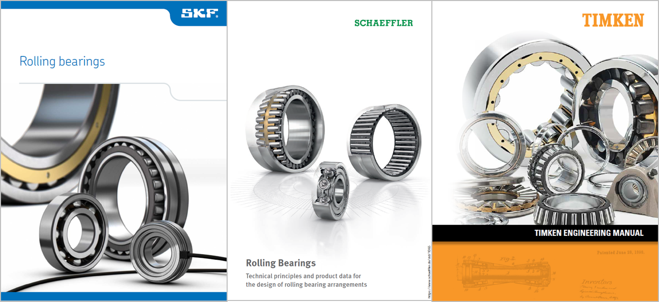 |
Figure: Current SKF, SCHAEFFLER, and TIMKEN bearing catalogs from 2020
The following only provides a rough overview of the calculation methods. For more detailed information, refer to the manufacturers' bearing catalogs, which are available free of charge.
SKF 2020
The SKF catalog method is the most precise and detailed calculation approach for determining the power loss. The individual friction torque amounts are summed to determine the total torque loss. This can also be used to identify which amount of torque loss is the greatest and where improvements may be achieved.
Symbol | Description | Unit |
M | Total friction torque | Nm |
Mrr | Rolling friction torque | Nm |
Msl | Sliding friction torque | Nm |
Mseal | Friction torque of contact seals | Nm |
Mdrag | Friction torque due to flow, splash, or spray losses | Nm |
Symbol | Description | Unit |
Mrr | Rolling friction torque | Nm |
ϕish | Lubricating film thickness factor for rolling friction torque | - |
ϕrs | Kinematic lubricant displacement factor for rolling friction torque | - |
Grr | Basic rolling friction value, depending on the bearing geometry and input load | - |
νOil | Kinematic operating oil viscosity | mm²/s |
n | Relative speed between bearing inner and outer ring | 1/min |
Symbol | Description | Unit |
Msl | Sliding friction torque | Nm |
Gsl | Basic sliding friction value, depending on the bearing geometry and input load | - |
µsl | Coefficient of sliding friction | - |
Symbol | Description | Unit |
Mseal | Friction torque of the contact seals | Nm |
KS1 | Coefficient of sealing friction 1, depending on the seal and bearing types and the bearing dimensions | - |
dS | Diameter of the mating surface of the seal | mm |
β | Sealing friction exponent, depending on the seal and bearing type | - |
KS2 | Coefficient of sealing friction 2, depending on the seal and bearing types and the bearing dimensions | - |
Ball bearings
Cylindrical roller bearings
Symbol | Description | Unit |
Mdrag | Friction torque due to flow, splash, or spray losses for oil bath lubrication | Nm |
VM | Flow loss factor | - |
Kball, Kroll | Rolling element-related constants, depending on the bearing type and dimensions as well as the number of rolling elements | - |
dm | Average bearing diameter 0.5·(d+D) | mm |
n | Relative speed between bearing inner and outer ring | 1/min |
ft | Factor for immersion depth in oil bath, depending on the bearing dimensions and oil level | - |
νOil | Kinematic operating oil viscosity | mm²/s |
RS | Oil bath factor, depending on the bearing type and dimensions as well as the oil level | - |
Additional information on the calculation can be found in the SKF Bearing Catalog.
There is also an SKF Online Tool for bearing calculations, which includes the power loss.
SCHAEFFLER 2020
The SCHAEFFLER catalog method is based on simple empirically determined characteristics for calculation of the total friction torque as a function of the load-dependent and load-independent loss amounts. Axial loads are considered separately.
Symbol | Description | Unit |
MR | Total friction torque | Nm |
M0 | Load-independent bearing friction torque | Nm |
M1 | Load-dependent bearing friction torque | Nm |
M2 | Bearing friction torque for axially loaded cylindrical roller bearings | Nm |
Speed-dependent friction torque
for
or
for
Symbol | Description | Unit |
M0 | Load-independent bearing friction torque | Nm |
f0 | Load-dependent bearing friction torque | - |
νOil | Kinematic operating oil viscosity | mm²/s |
n | Relative speed between bearing inner and outer ring | 1/min |
dm | Average bearing diameter 0.5·(d+D) | mm |
Load-dependent friction torque
for needle and cylindrical roller bearings
for ball, bevel, and spherical roller bearings
Symbol | Description | Unit |
M1 | Load-dependent bearing friction torque | Nm |
f1 | Load-dependent bearing friction factor | - |
F | Radial load for radial bearings and axial load for axial bearings | N |
dm | Average bearing diameter 0.5·(d+D) | mm |
P1 | Relevant load for friction torque | N |
Symbol | Description | Unit |
M2 | Bearing friction torque for axially loaded cylindrical roller bearings | Nm |
f2 | Bearing friction factor, depending on the axial load | - |
Fa | Axial dynamic bearing load | N |
dm | Average bearing diameter 0.5·(d+D) | mm |
Additional information on the calculation can be found in the SCHAEFFLER Bearing Catalog.
There is also a SCHAEFFLER Online Tool for bearing calculations, which includes the power loss.
TIMKEN 2020
The TIMKEN catalog method is based on simple empirically determined characteristic values for calculation of the total friction torque as a function of the load-independent and load-dependent losses. The formula is very similar to the SCHAEFFLER calculation.
for
or
for
with
Radial ball bearings:
Radial cylindrical and spherical roller bearings:
Thrust, cylindrical roller, and spherical roller thrust bearings:
Symbol | Description | Unit |
M | Total friction torque | Nm |
f1 | Load-dependent bearing friction factor | - |
Fβ | Bearing load for the load-dependent bearing friction torque | N |
Fa, Fr | Axial or radial bearing load | N |
α | Nominal contact angle | deg |
f0 | Load-independent bearing friction factor | - |
dm | Average bearing diameter 0.5·(d+D) | mm |
νOil | Kinematic operating oil viscosity | mm²/s |
n | Relative speed between bearing inner and outer ring | 1/min |
Tapered roller bearings
Single-row:
Double-row:
Symbol | Description | Unit |
M | Total friction torque | Nm |
k1 | Bearing torque constant | - |
G1 | Geometry factor | - |
νOil | Kinematic operating oil viscosity | mm²/s |
n | Relative speed between bearing inner and outer ring | 1/min |
f3 | Combined load factor | - |
Fr | Radial load | N |
K | K factor | - |
FrA, FrB | Radial load of row A or B | N |
Additional details on the calculation are available in the TIMKEN bearing catalog.
ISO 14179-2
The calculation of bearing losses according to ISO 14179-2 corresponds to the SKF bearing catalog method from 1994.
Symbol | Description | Unit |
M | Total friction torque | Nm |
M0 | Load-independent bearing friction torque | Nm |
M1 | Load-dependent bearing friction torque | Nm |
M2 | Bearing friction torque for axially loaded cylindrical roller bearings | Nm |
Speed-dependent friction torque
for
or
for
Symbol | Description | Unit |
M0 | Load-independent bearing friction torque | Nm |
f0 | Load-independent bearing friction factor, depending on the bearing and lubrication types | - |
dm | Average bearing diameter 0.5·(d+D) | mm |
νOil | Kinematic operating oil viscosity | mm²/s |
n | Relative speed between bearing inner and outer ring | 1/min |
Load-dependent friction torque
Symbol | Description | Unit |
M1 | Load-dependent bearing friction torque | Nm |
f1 | Load-dependent bearing friction factor | - |
P1 | Equivalent bearing load for friction torque | N |
a, b | Exponents | - |
dm | Average bearing diameter 0.5·(d+D) | mm |
Symbol | Description | Unit |
M2 | Bearing friction torque for axially-loaded cylindrical roller bearings | Nm |
f2 | Bearing friction factor, depending on the axial load | - |
Fa | Axial dynamic bearing load | N |
dm | Average bearing diameter 0.5·(d+D) | mm |
When this calculation method is selected, factors f0 and f1 must be specified manually. The relevant tables from ISO 14179-2 can be found in the Attribute Help.
Plain bearing losses
Power loss from plain bearings is calculated in the COMBROS R & A modules, which have long been integrated into the FVA-Workbench for iterative solution of the overall system. The friction torques calculated in COMBROS are considered in the determination of losses in the overall system.
Combros R&A
The COMBROS R (radial) and A (axial) calculation modules were developed at the TU Clausthal ITR (Institut für Tribologie und Energiewandlungsmaschinen) as part of FVA Projects FVA 577, FVA 668II, and FVA 677.
Planet carrier losses
Planet carrier power losses with single-plate carriers are a result of the carrier and planets splashing in oil. For dual-plate carriers, the planets do not have any additional influence on the splash losses, as they are located within the planet carrier.
The losses from the rotation of the planets are considered separately and added to those of the planet itself.
The methodology for calculation of planet carrier losses was developed by KETTLER.
Single-plate planet carriers according to KETTLER
For open single-plate planet carriers, the splash losses of the carrier and the planets rotating within it are added together.
Symbol | Description | Unit |
PVST | Single-plate planet carrier splash power loss | W |
PVST,sw1 | Single-plate planet carrier side plate splash power loss | W |
PVST,sr1 | Single-plate planet carrier planet gear splash power loss due to rotation of the carrier | W |
Symbol | Description | Unit |
PVST,sw1 | Single-plate planet carrier side plate splash power loss | W |
dSt1 | Total diameter of the single-plate planet carrier | m |
bSt1 | Rim width of the single-plate planet carrier | m |
Fe,St1 | Planet carrier side plate oil level influence factor | - |
ns0 | Planet carrier speed | min-1 |
νOil | Kinematic operating oil viscosity | mm2/s |
ρOil | Oil density at operating temperature | kg/m3 |
where
if
or
if
and
or
if
Symbol | Description | Unit |
Fe,St1 | Single-plate planet carrier side plate oil level influence factor | - |
sOil | Oil level relative to the center of the gear | m |
dSt1 | Total diameter of the single-plate planet carrier | m |
Symbol | Description | Unit |
PVST,sr1 | Single-plate planet carrier planet gear splash power loss due to rotation of the carrier | W |
FakPl1 | Single-plate planet carrier number of planetary gears influence factor | - |
a | Center distance | m |
da,Pl | Planetary gear tip diameter | m |
bPl | Planetary gear width | m |
Fe,aSt1 | Single-plate planet carrier planetary gear oil level influence factor | - |
ns0 | Planet carrier speed | min-1 |
ρOil | Oil density at operating temperature | kg/m3 |
where
if
or
if
and
if
or
if
or
if
Symbol | Description | Unit |
FakPl1 | Single-plate planet carrier number of planetary gears influence factor | - |
zPl | Number of planets | - |
Fe,aSt1 | Single-plate planet carrier planetary gear oil level influence factor | - |
sOil | Oil level relative to the center of the gear | m |
a | Center distance in the coordinate system | m |
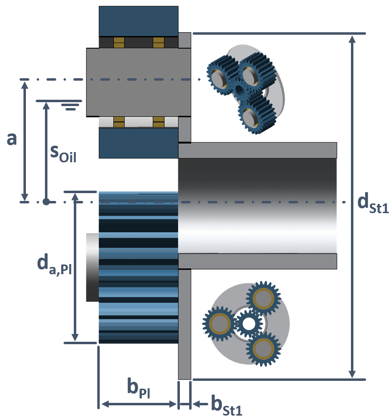 |
Figure: Single-plate planet carrier geometric data
Dual-plate planet carriers according to KETTLER
For open dual-plate planet carriers, the splash losses are caused exclusively by the carrier splashing in oil.
Symbol | Description | Unit |
PVST,sw2 | Dual-plate planet carrier side plate splash power loss | W |
dSt2 | Total diameter of the dual-plate planet carrier | m |
bSt2 | Dual-plate planet carrier rim width | m |
Fe,St2 | Dual-plate planet carrier planetary gear oil level influence factor | - |
ns0 | Planet carrier speed | min-1 |
νOil | Kinematic operating oil viscosity | mm²/s |
ρOil | Oil density at operating temperature | kg/m³ |
where
if
or
if
and
or
if
Symbol | Description | Unit |
Fe,St2 | Dual-plate planet carrier planetary gear oil level influence factor | - |
sOil | Oil level relative to the center of the gear | m |
dSt2 | Total diameter of the dual-plate planet carrier | m |
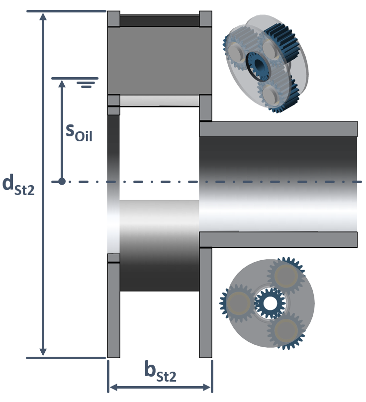 |
Figure: Dual-plate planet carrier geometric data
Sealing losses
Power loss from radial shaft seals are a result of friction between the seal, which is generally fixed, and the rotating shaft. These friction losses depend on various factors, such as the seal material, hardness of the shaft material, surface roughness of the shaft in the area of the seal lip, the lubricant, and the temperature at the location of the seal. The calculation is performed using simplified empirically determined formulas and factors.
ISO 14179-1 (USA)
ISO/TR 14179-1 is the American ISO approach for gearbox thermal balance calculations. It includes calculation of the sealing losses based on the rules and regulations of the Association for Rubber Products Manufacturers (ARPM OS-15).
where
for VITON
for BUNA N
Symbol | Description | Unit |
PVD | Power loss at the seal | W |
dsh | Shaft diameter at the seal | mm |
n | Speed of the shaft relative to the seal | 1/min |
ISO 14179-2 (Germany)
ISO/TR 14179-2 is the German ISO approach for gearbox thermal balance calculations. It includes calculation of the sealing losses based on the Simrit/Freudenberg (SIMRIT) catalog for radial shaft seals.
Symbol | Description | Unit |
PVD | Power loss at the seal | W |
dsh | Shaft diameter at the seal | mm |
n | Speed of the shaft relative to the seal | 1/min |
LINKE
Heinz Linke describes an extension of the ISO 14179-2 approach for calculating sealing losses in his book on cylindrical gears (LINKE). This approach extends the calculation to include the influence of the lubricant at different operating temperatures.
Symbol | Description | Unit |
PVD | Power loss at the seal | W |
ϑOil | Oil operating temperature | °C |
ν40 | Kinematic viscosity of the lubricant at 40°C | mm2/s |
dsh | Shaft diameter at the seal | mm |
n | Speed of the shaft relative to the seal | 1/min |
Sources
Standards
ISO/TR 14179-1:2001(E): Gears - Part 1: Rating gear drives with thermal equilibrium at 95° C sump temperature, 2001
ISO/TR 14179-2:2001(E): Gears - Part 2: Thermal load-carrying capacity, 2001
DIN 3996:2019-09: Calculation of load capacity of cylindrical worm gear pairs with rectangular crossing axes, 2019
DIN 31652-1:2017-01: Plain bearings - Hydrodynamic plain journal bearings under steady-state conditions - Part 1: Calculation of circular cylindrical bearings, 2017
DIN 31653-1:1991-05: Plain bearings; hydrodynamic plain thrust bearings under steady-state conditions; calculation of pad thrust bearings, 1991
DIN 31654-1:1991-05: Plain bearings; hydrodynamic plain thrust bearings under steady-state conditions; calculation of tilting-pad thrust bearings, 1991
DIN 31657-1:1996-03: Plain bearings - Hydrodynamic plain journal bearings under steadystate conditions - Part 1: Calculation of multi-lobed and tilting pad journal bearings, 1996
Books, Catalogs, Instruction Manuals
SIMRIT: Radialwellendichtringe, Katalog Nr. 100, 1976
ESCHMANN, P. u. a.: Die Wälzlagerpraxis. Oldenburg München-Wien, 1978
NIEMANN, G., WINTER, H.: Machine Elements, Vol. 3, Berlin: Springer, 1983
FREUDENBERG: Simmering/Radial-Wellendichtringe, Katalog Nr. 100 Ausgabe 1/86
ARPM OS-15: Measuring Radial Lip Seal Torque and Power Consumption, Association for Rubber Products Manufacturers, 1986
LINKE, H.: Stirnradverzahnung, 2. Auflage, Carl Hanser Verlag München Wien, 2010
SKF: Rolling bearings, catalogue, PUB BU/P1 17000/1 EN, 2018
SCHAEFFLER: Rolling bearings, catalogue, HR 1, 2018
TIMKEN: Engineering manual bearings, catalogue, 2011
WTplus: FVA-EDV Programm WTplus, Version 2.2.1, Benutzeranleitung, 2016
Dissertations and Publications
OHLENDORF, H.: Verlustleistung und Erwärmung von Stirnrädern, TH München, Diss., 1958
ARIURA, Y.: Lubricant churning loss in spur gear systems, JSME Vol. 16, pp. 881 -891, Veröffentlichung, 1973
WALTER, P.: Anwendungsgrenzen für die Tauchschmierung von Zahnradgetrieben, Plansch- und Quetschverluste bei Tauchschmierung, Universität Stuttgart, Diss., 1982
MAUZ, W.: Hydraulische Verluste bei Tauch- und Einspritzschmierung von Zahnradgetrieben, Universität Stuttgart, Diss., 1985
WECH, L.: Untersuchungen zum Wirkungsgrad von Kegelrad- und Hypoidgetrieben, TU München, Diss., 1987
BUTSCH, M.: Hydraulische Verluste schnelllaufender Stirnradgetriebe, Universität Stuttgart, Diss., 1989
SCHLENK, L.: Untersuchungen zur Fresstragfähigkeit von Großzahnrädern,TU München, Diss., 1995
BARTON, P. M.: Tragfähigkeit von Schraubrad- und Schneckengetrieben der Werkstoffpaarung Stahl/Kunststoff, Ruhr-Universität Bochum, Diss., 2000
DOLESCHEL, A.: Wirkungsgradberechnung von Zahnradgetrieben in Abhängigkeit vom Schmierstoff, TU München, Diss., 2002
WASSERMANN, J.: Einflussgrößen auf die Tragfähigkeit von Schraubradgetrieben der Werkstoffpaarung Stahl/Kunststoff, Ruhr-Universität Bochum, Diss., 2005
WIMMER, A.: Lastverluste von Stirnradverzahnungen - Konstruktive Einflüsse, Wirkungsgrad-maximierung, Tribologie, TU München, Diss., 2006
WENDT, T.: Tragfähigkeit von Schraubradgetrieben mit Schraubrädern aus Sintermetall, Ruhr-Universität Bochum, Diss., 2008
PECH, M.: Tragfähigkeit und Zahnverformung von Schraubradgetrieben der Werkstoffpaarungen Stahl/Kunststoff, Ruhr-Universität Bochum, Diss., 2011
MILTENOVIC, A.: Verschleißtragfähigkeitsberechnung von Schraubradgetrieben mit Schaubrädern aus Sintermetall, Ruhr-Universität Bochum, Diss., 2011
SUCKER, J.: Entwicklung eines Tragfähigkeitsberechnungsverfahrens für Schraubradgetriebe mit einer Schnecke aus Stahl und einem Rad aus Kunststoff, Ruhr-Universität Bochum, Diss., 2012
Forschungsvereinigung Antriebstechnik e.V. (FVA), Frankfurt/Main
MAUZ, W.: FVA-Heft 185: Zahnradschmierung-Leerlaufverluste, FVA Nr. 44 III, Abschlussbericht, 1985
MAURER, J.: FVA-Heft 432: Ventilationsverluste, FVA Nr. 44 VI, Abschlussbericht, 1994
SCHLENK, L.: FVA-Heft 443: Größeneinfluss Fressen, FVA-Nr. 166 I, Abschlussbericht, 1995
KETTLER, J.: FVA-Heft 639: Planetengetriebe-Sumpftemperatur, FVA-Nr. 313 I, Abschlussbericht, 2000
DOLESCHEL, A.: FVA-Heft 664: Wirkungsgradtest, FVA-Nr. 345 I, Abschlussbericht, 2001
GEIGER J.: FVA-Heft 959: Validierung WTplus, FVA-Nr. 69 V, Abschlussbericht, 2010
HAGEMANN, T.: FVA-Heft 996: Verbesserte Radialgleitlagerberechnung, FVA-Nr. 577 I, Abschlussbericht, 2011
PFEIFFER P.: FVA-Heft 1184: Radialkippsegmentlager Ölzuführungseinfluss, FVA-Nr. 677 I, Abschlussbericht, 2016
SEDLMAIR M.: FVA-Heft 1208: Erweiterung WTplus, FVA-Nr. 69 VI, Abschlussbericht, 2017
OEHLER, M.: FVA-Heft 1226: Schneckengetriebewirkungsgrade, FVA-Nr. 729 I, Abschlussbericht, 2017
JURKSCHAT, T.: FVA-Heft 1223: Verlustleistung von Stirnradverzahnungen, FVA-Nr. 686 I, Abschlussbericht, 2017
FINGERLE A.: FVA-Heft 1282: Durchgängige Berechnung gleitgelagerter Welle-Lager-Systeme, FVA-Nr. 668 II, Abschlussbericht, 2018
SEDLMAIR M.: FVA-Heft NA: Innenverzahnungen - Reibung und Wärme, FVA-Nr. 584 II, ongoing project, 2022