Spline connection
Spline connection are machine elements that connect a shaft with a hub, and serve to transmit torque as well as centering the shaft and hub relative to each other. The geometry design of spline gears in the FVA-Workbench is based on DIN 5480 Part 1 (2006).
Spline connection load capacity calculations are performed according to DIN 5466 Part 1 (2000), with extensions from FVA Research Project 591. The factors for permissible stress and safety of spline gears according to Niemann/Winter/Höhn Machine Elements Volume 1 are also included in the strength calculation.
Geometry acc. to DIN 5480
The geometry of spline connections is defined by various national and international standards, such as ANSI B92.1, DIN 5480, and ISO 4156. Spline connection geometry calculations in the FVA-Workbench are performed according to DIN 5480. DIN 5480 spline connections are based on reference diameters for connecting hubs and shafts with a separable connection, a sliding fit, or a tight fit.
The underlying principles of DIN 5480 for estimating spline connection geometry are listed below:
The standard covers intermeshing spline gears in the module range from 0.5 through 10, between 6 and 82 teeth, and a pressure angle of 30°.
The basic rack profile is the same for all pitches, so that a uniform design rule applies for all profiles.
The centering (flank or diameter) can be selected based on the design requirements of the spline connection.
The fit and centering accuracy are determined based on the achieved or specified dimensions and tolerances. Thus, the effect of these dimensions and tolerances on the fit clearance is considered.
Based on the principles above, the basic rack profile of the spline connection can be estimated in the FVA-Workbench input wizard:
DIN 5480 Table According to DIN 5480 Table 1, the reference diameter (d_B) and normal module (m) must be specified as input parameters, and the number of teeth (Z), addendum modification coefficient (x), and the tip circle diameter (da) are estimated based on these input values.
DIN 5480 Formulas According to the formulas in DIN 5480 (Table 3), 3 of 4 known rack profile parameters can be specified: reference diameter (d_B), normal module (m), number of teeth (Z), addendum modification coefficient (x). The unknown parameter can be approximated based on the specified input values.
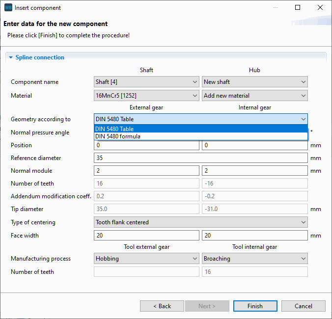 |
FVA-Workbench spline connection wizard
The nominal dimensions for the centering diameter, tolerance and deviation series for tooth thickness, and the tip and root diameter of splined shafts and hubs are automatically applied based on the type of centering selected.
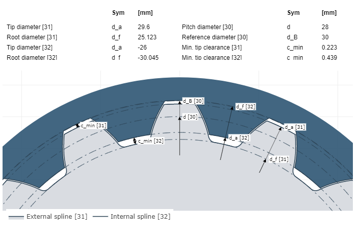 |
Representation of the nominal dimensions of a flank-centered spline gear from an FVA-Workbench results report.
DIN 5480 offers a limited number of fit variants. For improved assessment of the fit precision and concentricity, these variants were extensively supplemented based on FVA Research Project 591 to offer an extended range of deviation series for shafts and hubs.
The calculated tolerance values, which are based on the nominal dimensions for the tooth gap and tooth thickness, can be visualized in FVA-Workbench results. The finishing tools (rack and cutter) are automatically selected based on the type of manufacturing process selected in the wizard.
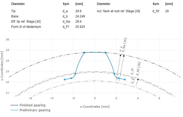 | 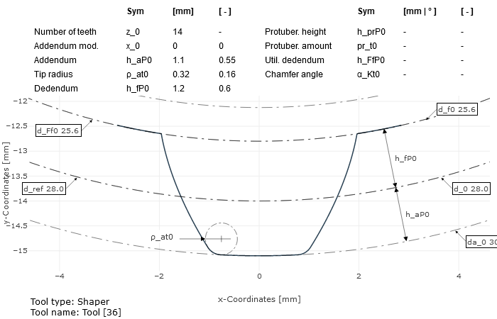 |
Tooth profile of a splined shaft (left), tooth profile of a cutting wheel tool (right) from an FVA-Workbench results report
Load carrying capacity acc. to DIN 5466
Spline connection are the most commonly used shaft-hub connection for transmitting high torques. In the FVA-Workbench, spline connection are designed according to DIN 5466 Part 1 (2000), with enhancements from FVA Research Project 591. The standard includes methods for estimating the maximum load and the pressure on the flanks, the wear behavior, and for calculating the stresses in the notched area of the shaft and hub:
The standard covers the basics of the load capacity calculation for both flank and diameter-centered spline connection with clearance and transition fits. It does not cover press fits. The geometry of the spline connection corresponds to DIN 5480, and the ratio of the outer diameter of the hub to the reference diameter should be 1.5 < d_e2/d_B.
Based on the operating conditions, the following parameters are considered critical for causing stress in the notch area:
External loads due to torque, transverse force, axial force, and bending moment
Clearance, pitch, and tooth thickness deviations from the selected tolerances and fits
Elastic behavior of the connection
Friction, lubrication, and wear in flank-centered connections.
In accordance with DIN 5466, the factors used in the calculation of the stresses from torsion, bending moment, transverse force, axial force, and maximum flank normal force were taken from the results of FVA Research Project 591.
Tolerance-related parameters such as clearance, pitch, tooth thickness variations, and the influence of the material stiffness are considered in the stress calculation.
Based on the principles listed above, methods have been implemented for estimating the flank pressure, load, and stresses in the notch area of the flank. The load capacity calculation for spline connections requires a realistic evaluation of the influencing factors, especially the permissible pressure in the tooth contact and the safety factor.
Due to manufacturing deviations and tooth misalignments, the loads acting on the gear are not uniformly distributed across all the teeth and the face width. This leads to uneven flank pressure, which is considered via two influencing factors:
Circumferential load distribution factor kφ This factor considers the load distribution behavior of the spline connection over the circumference of the connection. It is dependent on the tooth geometry. In the FVA-Workbench, the circumferential load distribution factor can either be determined according to FVA 591 or specified by the user.
Face load factor kb This factor considers the load distribution over the load bearing length of the teeth from twisting of the shaft and hub due to torque. In the FVA-Workbench, the face load factor can either be determined according to FVA 591 or specified by the user.
The permissible stress and the corresponding safety factor are determined according to Niemann/Winter/Höhn Machine Elements Volume 1, depending on the material.