FVA-Workbench 9.0.0
Features
In addition to the previous range of functions, there is now a new option for specifying load spectra. This is done via the "Type of load spectrum" button in the Calculation Parameters tab for the Gear Unit.
The following data can be freely selected for each load case: time share, operating temperature, switch position/gear, power flow data, external loads
Copy-paste can also be used to enter data from Excel column-by-column
The creation of a model snapshot for each load case with all detailed results can be activated. A model snapshot is also created with the accumulated results and overview tables.
Revised load spectrum calculation for bevel gears according to ISO 10300
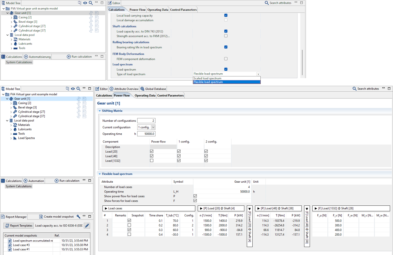
Flexible load spectrum calculations can be activated under the Calculation Parameters tab for the Gear Unit component by selecting "Type of load spectrum" -> "Flexible load spectrum." The parameters for the load cases are then set under the Power Flow tab.
The new Transmission Ratio Element component (transmission_ratio_element) couples the rotational degrees of freedom of any two shafts with a freely selectable transmission ratio. A transmission ratio profile curve can be specified. The ability to flexibly set the transmission ratio in the load spectrum greatly simplifies the modeling of auxiliary units or hydrostats.
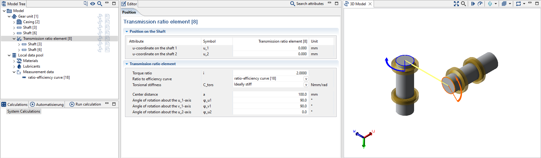
Right-click on a shaft in the Model Tree to add the new "Transmission ratio" component.
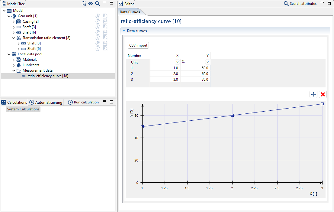
A transmission-efficiency curve can then be specified as a measurement data database component.
Split FEM gearbox casings
With FVA-Workbench 9.0, gearbox casings can now be imported and meshed as an assembly of individual CAD parts. This helps to avoid errors when merging CAD parts and saves time due to coarser meshing of less important components. This method minimizes errors and speeds up the process.
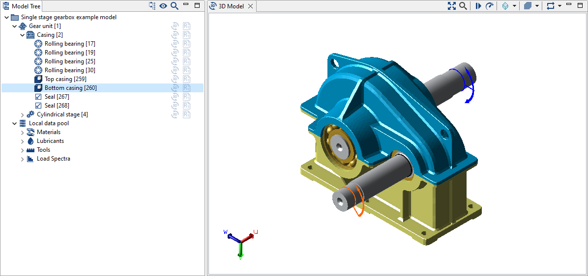
The parts of the casing are shown as separate components in the Model Tree.
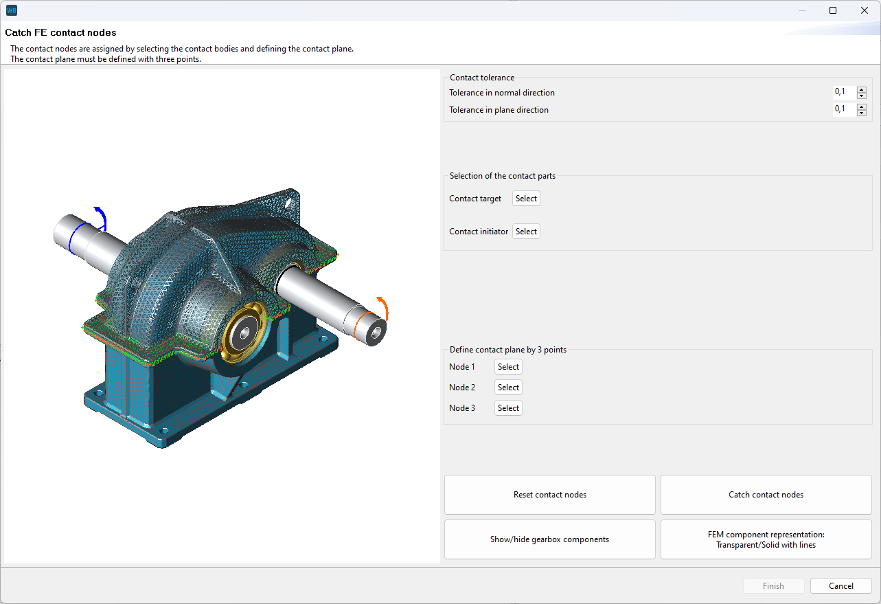
A new Assistant can be used to semi-automatically determine the contact nodes between the casing parts.
Additional new FEM features
An FE converter has been integrated. FE files in the Nastran *.bdf and *.nas formats can now also be imported.
Reduced stiffness matrices can now be exported and imported.
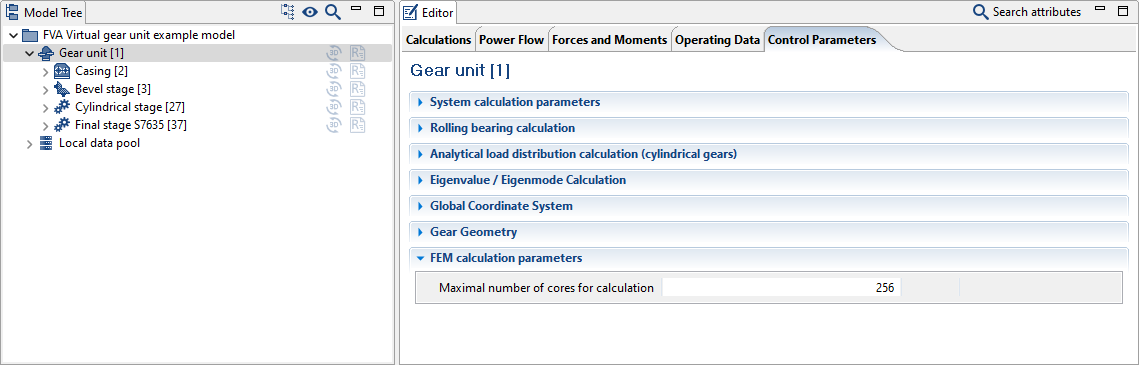
The number of CPU cores to be used for FE calculations can now be set.
All bearings and couplings can now be selected as a reference for the axial positioning of the gearbox casing in the Assistant.
Improved proposed modification for cylindrical gear stages with FE wheel bodies.
Consideration of backlash
The backlash of cylindrical gear stages can now be considered in the overall system in the calculation of the static angle of rotation. This makes it easier to compare the load-free angle of rotation with measurements.
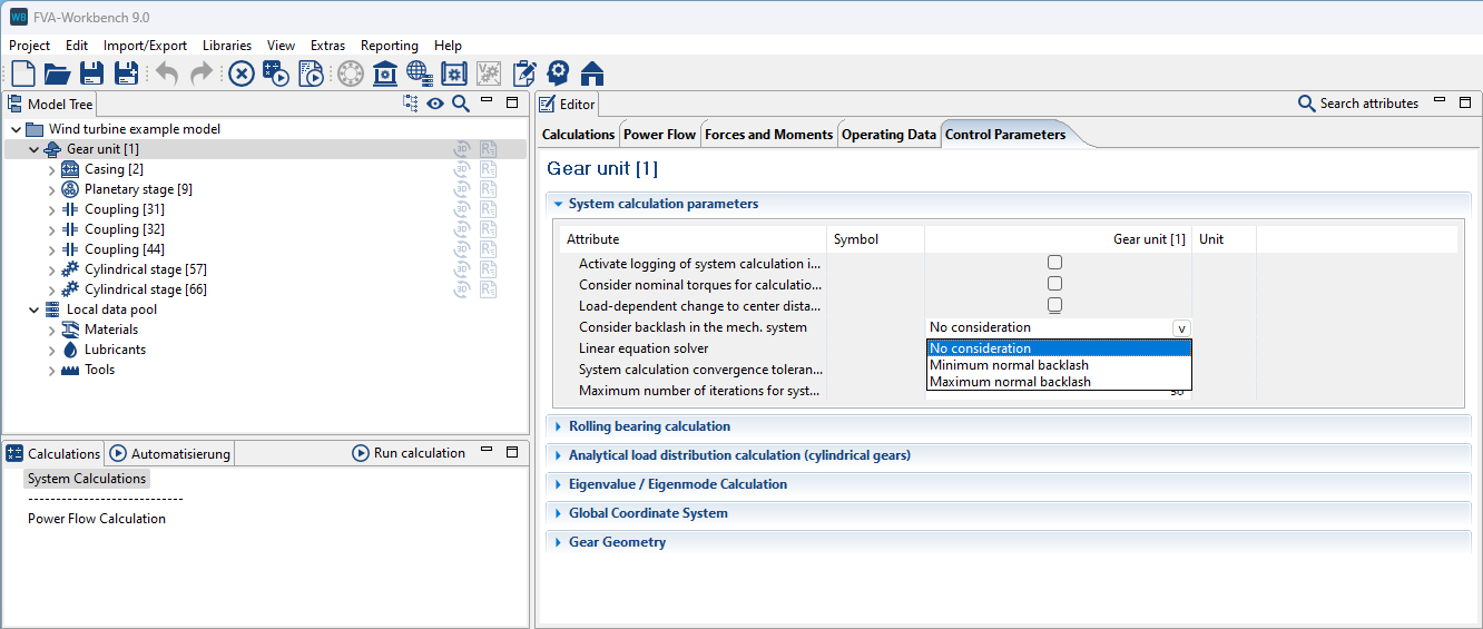
The maximum, minimum, or no backlash can be considered in the system calculation.
Backlash deviations in planetary stages
Backlash deviations between the planets can also be considered in planetary stages. These may be additive to the backlash above.
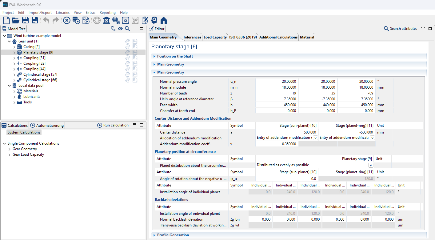
The meshing backlash deviation (normal section) or angular backlash deviation (transverse section) can be specified for each of the engagements in the planetary stage.
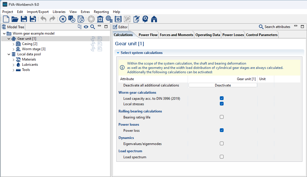
Load capacity and tooth contact of worm gearboxes in the overall system
The calculation of worm stages as part of the system calculation ensures a consistent power flow. The results for the load capacity and the local load distribution are shown in the report.
Improved initial bearing stiffness
The automatically determined initial bearing stiffness and thus the convergence of the overall system has been improved. This is particularly effective for bearings with backlash and low loads.
New features
The calculations according to ISO 6336-20 and ISO 6336-21 have been brought up to the current status as of 2022-05; performance has also been improved.
The tooth root load capacity calculation for ring gears according to FVA 45 II has been revised
The actual overlap ratio and transverse contact ratio under load are determined from the contact pattern. The microgeometry is also considered (e.g.; crowning, etc.).
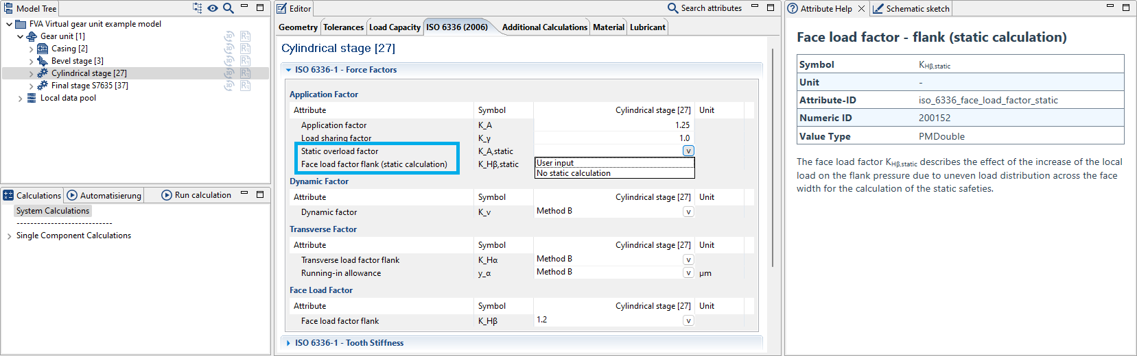
A face load factor can now also be specified for the static calculation according to ISO 6336.
An error message is now displayed if the calculated local flash temperature exceeds 500°C.
The scuffing temperatures from a scuffing test can also now be specified as an alternative to specifying a scuffing load level.
Full rounding of the tooth reference profile can now be specified.
Bevel gear design according to ISO 23509
The user guidance for bevel gear design according to ISO 23509 has been optimized. The parameters for tooth depth shape, outer circumferential backlash, and chordal tooth thickness factor can now easily be selected. These data can also still be manually specified.
Furthermore, the helix and pressure angles can now be edited for all available gear cutting methods. Protuberances and tip relief can be configured separately for each flank.
The Attribute Help has also been expanded.
Additional new features
A new version of the BECAL kernel has been integrated (version 6.4.2).
Report templates have been expanded (e.g., comparison of the tooth root safety for variant or load spectrum calculations).
System-level load spectrum calculations in the overall system according to ISO 10300 have been enhanced. Load spectrum calculations for other standards are now only available in single component calculations.
Additional calculations according to FVA research projects are now only available for calculation objectives according to ISO 10300.
Closed bevel gear chains: machine settings data can now be imported from bevel gear stages (such as bevel gear differentials).
A new "Amplitude of rotational deviations" diagram has been created for reports.
SKF calculation service enhancements
The functionality of the SKF calculation service has been significantly expanded. The following additional calculations are now available:
Nominal and extended SKF bearing life
Frictional torque and power loss calculations
Rollover frequencies
Static safety
Application-specific reference speeds
Minimum load
Grease service life and relubrication interval
Expansion of rolling bearing calculations in the FVA-Workbench
The internal calculation module for rolling bearings in the FVA-Workbench has been expanded:
The reference lifetime of catalog bearings can now be calculated according to ISO/TS 16281
Several additional calculations can now be performed for rolling bearings according to SKF and Schaeffler (minimum load, permissible speed, permissible axial load of cylindrical roller bearings)
The FVA bearing catalog has been removed (upgrade to internal geometry specification implemented).
Rolling bearing selection dialog
A search field has been added to the rolling bearing selection dialog.
Interference fits
The stress hypotheses for tapered and cylindrical interference fits has been expanded, along with numerous user-friendliness improvements. Calculations can now be performed according to the von Mises deformation hypothesis in addition to the shear stress hypothesis according to DIN 7190. This allows strain hardening curves to be considered in order to more precisely capture the material behavior during partial plasticization.
Option to select between the stress hypothesis according to DIN 7190 (mod. shear stress hypothesis) or shape modification hypothesis according to von Mises (new)
Stress-strain curves can be considered in the calculation using the shape modification hypothesis
Multiple interference fit calculations completely revised .
The additional offset for maximum/minimum fit is now output for the calculation of tapered interference fits.
Spline gear tolerance calculations
The tip and root diameters are now strictly determined according to the base tangent length deviations for spline gear calculations according to DIN 5480. The recommended diameters according to DIN 5480 Table 5 are also output for the different centering types. A sign error that deviated from the basic tolerance H has been corrected when determining the base tangent length of splined hubs.
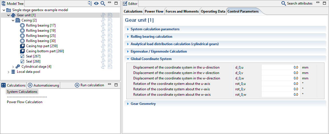
To simplify the positioning of CAD/FEM components, the FVA-Workbench global coordinate system can now be moved and rotated. To verify the global coordinate origin, right-click in the 3D Model and choose "show coordinate system."
Sub-headers can now be added in the Report Configurator. They help to group the results in the output report. The sub-headers are also shown in the Model Tree. When you click on a sub-header in the Model Tree, the report scrolls to the corresponding position.
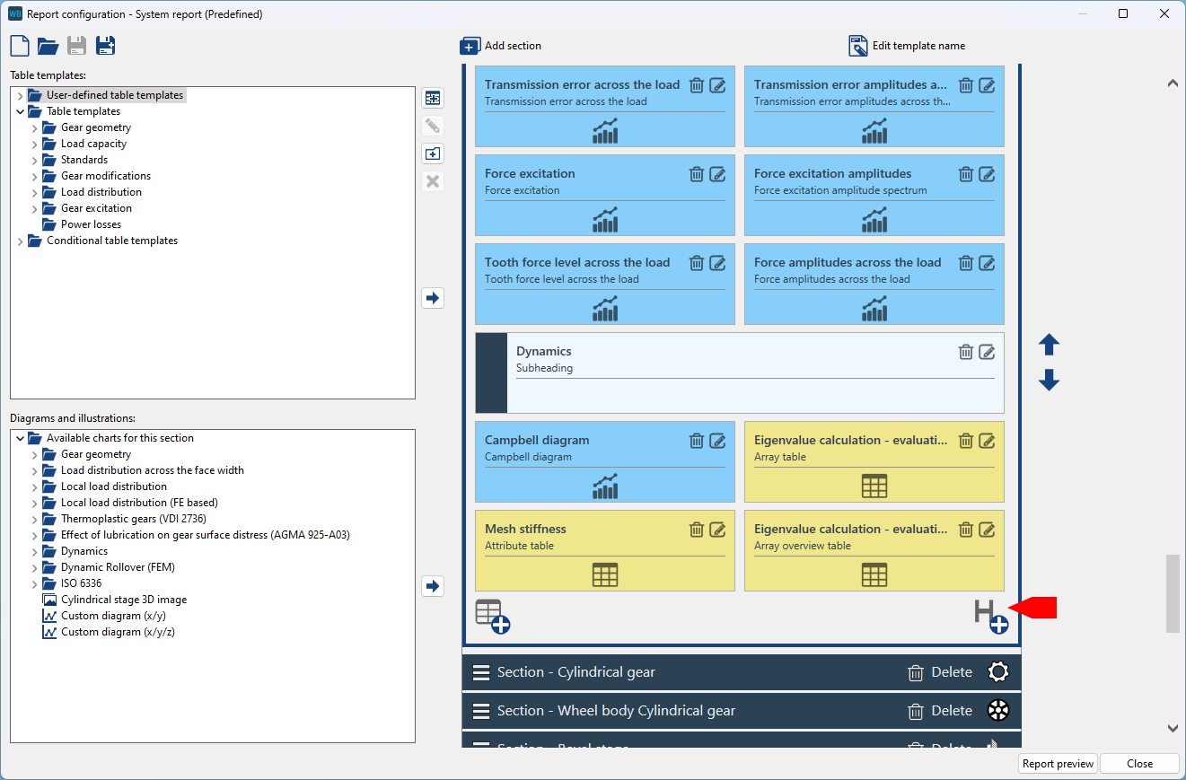
Sub-headers are added in the Report Configurator similar to results tables.
Two new buttons have been added to the Model Tree to hide components in the 3D Model and in output reports.
Import of REXS materials and lubricants
The FVA-Workbench also now supports importing database components for materials and lubricants as REXS files to facilitate the integration of custom data sets.
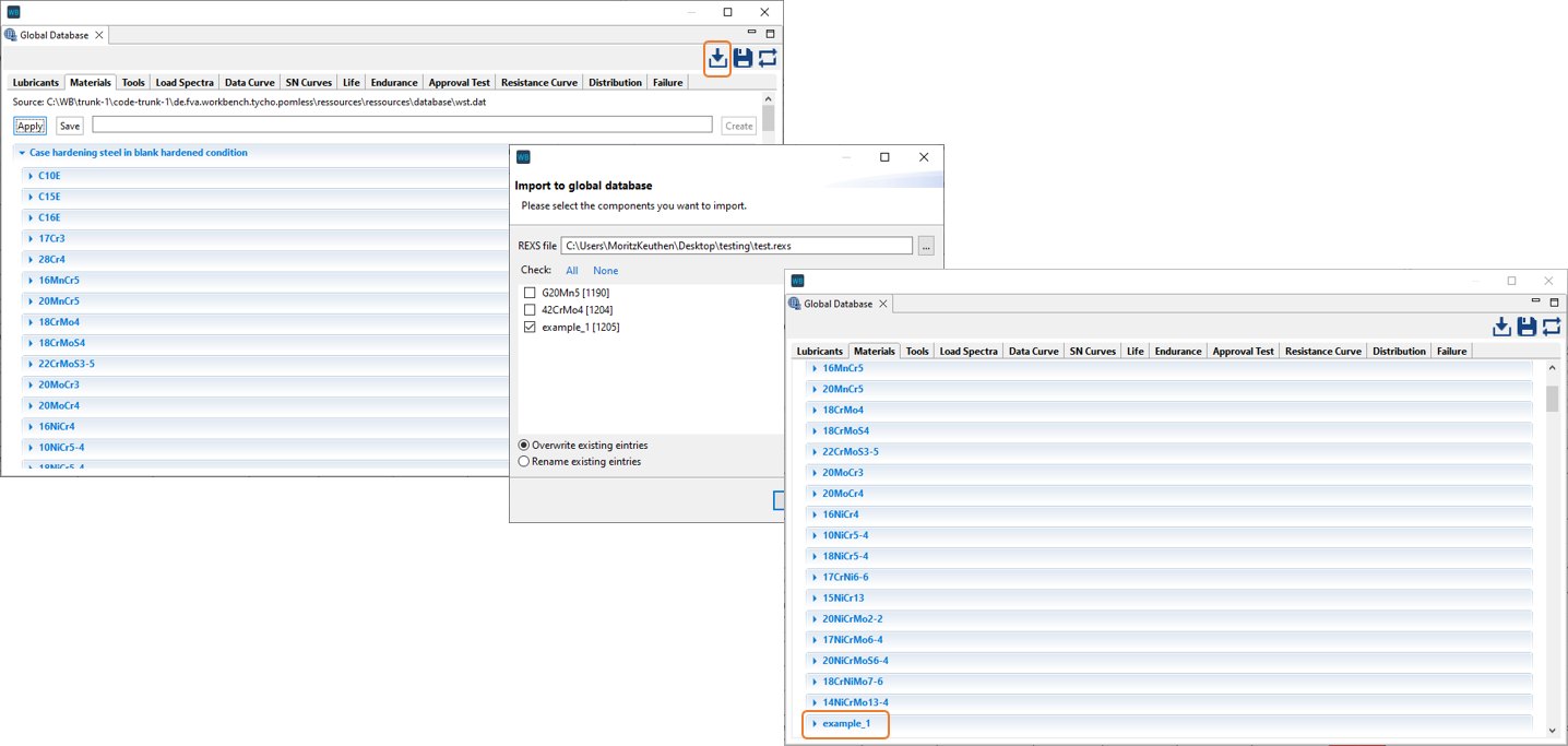
If multiple materials or lubricants are defined in the REXS file, the ones to be imported can be selected in the import dialog.
Support for REXS Version 1.6
Version 1.6 of the REXS format for exchanging gearbox models is now supported. The biggest change compared to version 1.5 is the ability to import and export plain bearings. Plain bearing tables are also supported.
Exporting 3D images of gearbox components
The new exportImage() feature can be used to export the complete gearbox model or individual components as an image. The orientation of the components and the image resolution can be configured. You can also specify whether the gearbox deformation should be considered during the export.
Revision of HTTP request functions
HTTP communication functions have been modified. These are breaking changes; i.e., existing scripts which use these functions must be updated. Essentially, the HTTP response has been packed into an object. This allows the response to be evaluated more accurately.
The following example executes an HTTP request and saves the response to the httpResponse variable. The information in the response, the HTTP status code (status), the status message (message), and the actual data (data) are then extracted and stored in separate variables.
let httpResponse = get('https://exampleurl/result');

let status  = httpResponse.status;
let message = httpResponse.message;
let data    = httpResponse.data;

if(status != 200){
    println("Something went wrong")
}
Components in rolling bearing selection dialog
Rolling bearings can be saved as components in the component library. The ability to select and add rolling bearings stored there via the rolling bearing selection dialog is new.
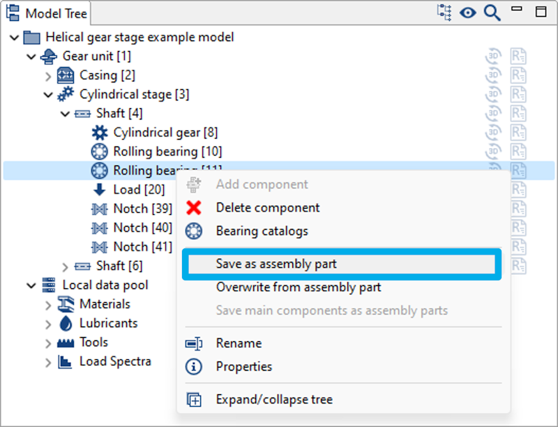
A rolling bearing can be saved as a component via the context menu.
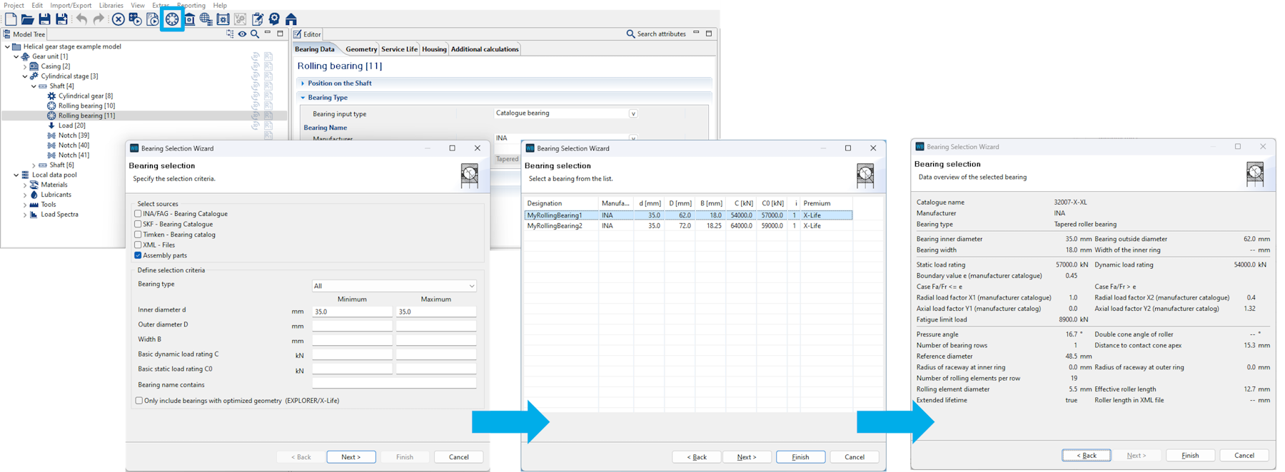
In addition to manufacturer catalogs, the component library can also be selected as a source in the rolling bearing selection dialog. Stored bearings can be selected from a list based on their geometry parameters.
Component names are automatically pre-assigned when saving
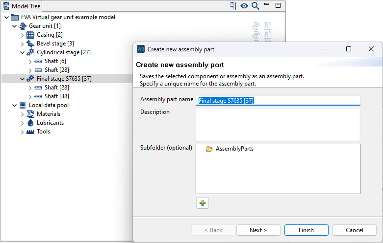
The name is now automatically pre-assigned when creating a new component.
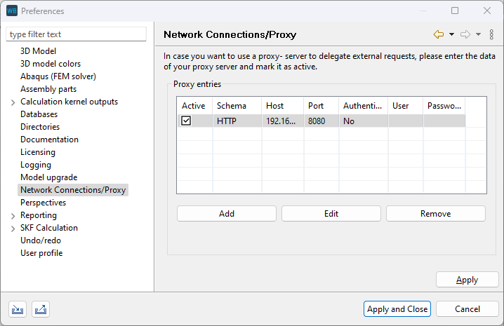
If the FVA-Workbench is used in a network that routes outgoing connections via a proxy server, the proxy server can now be configured in the settings. This configuration may be necessary if the SKF calculation service or scripting functions are used for client-server communication, in particular.
Overview of components for which a database component is used
If a database category such as material or lubricant is selected in the Model Tree, an overview of the gearbox components which use this database entry is now displayed.
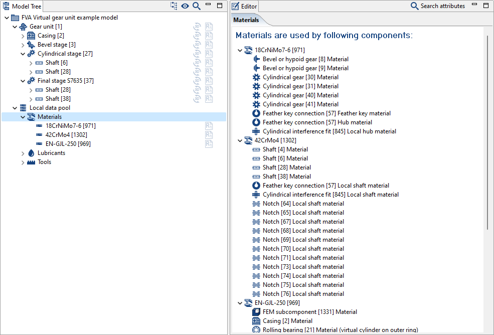
Three different materials are used in this example gearbox. The overview shows their use at a glance.
New material groups in the materials database
Several cast aluminum and plastic materials have been added to the materials database.
Bugfixes/improvements
Design calculation according to ISO 23509
Consideration of pressure angle modifications has been corrected. The Attribute Help for pressure angle modifications has been expanded, as this modification is implemented based on the gear cutting method.
Consideration of crowning has been corrected. The Attribute Help for crowning has been expanded to include a description of the dependency on the gear cutting method.
Consideration of helix angle modifications has been corrected. The Attribute Help has been expanded.
The internally determined default value according to ISO 23509 Table C.3 can be selected for the angular backlash j_en.
Addtional
Some older FVA-Workbench or REXS models do not include bevel wheel bodies. These are now automatically added when opening the model.
Report templates for the local load capacity calculation with comparison of variants have been expanded to include the diagram for comparing the minimum tooth root safeties.
An error which led to an incorrect sign in the bending moment for axial force with lever arm in the v direction has been corrected.
An error when importing graphic data from SNETRA has been corrected.
An error which prevented meshing when the 3D View is closed has been corrected.
An error in the calculation of the stress ratio in the FKM calculation with FE-based form factors has been corrected.
An error in the correction of hub splines has been corrected: when a basic dimension not equal to H was specified it was considered with the wrong sign for the hub gear.
The positioning of worm gear stages has been revised and expanded: the rotation now takes place about the positive u1 and w1 axes. Another new feature is the ability to subsequently rotate about the u2 axis.
Corrections in the friction torque calculation of rolling bearings