Pre-dimensioning of bevel gears according to ISO 23509
This tutorial will demonstrate the pre-dimensioning of the geometry of a bevel gear stage according to ISO 23509. After pre-dimensioning, the bevel gear stage contains all the information required for standard calculations and the advanced local gear calculations. After the calculation is completed, the machine settings (Standard.KGD) can be exported.

Create a new model
 (Project → New)
Add a bevel gear stage
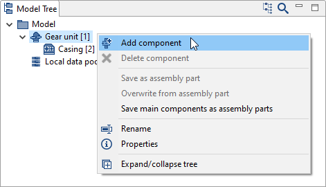
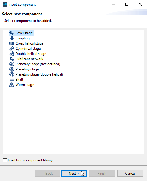
Right-click on the gear unit in the Model Tree and add a new bevel gear stage component.
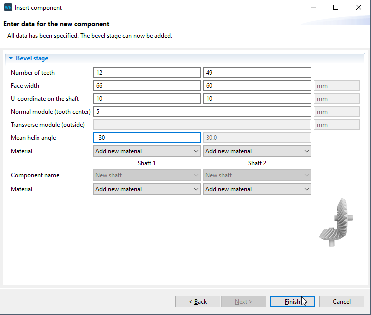
Specify the gear data
Enter the gear data in the assistant as shown in the image below.
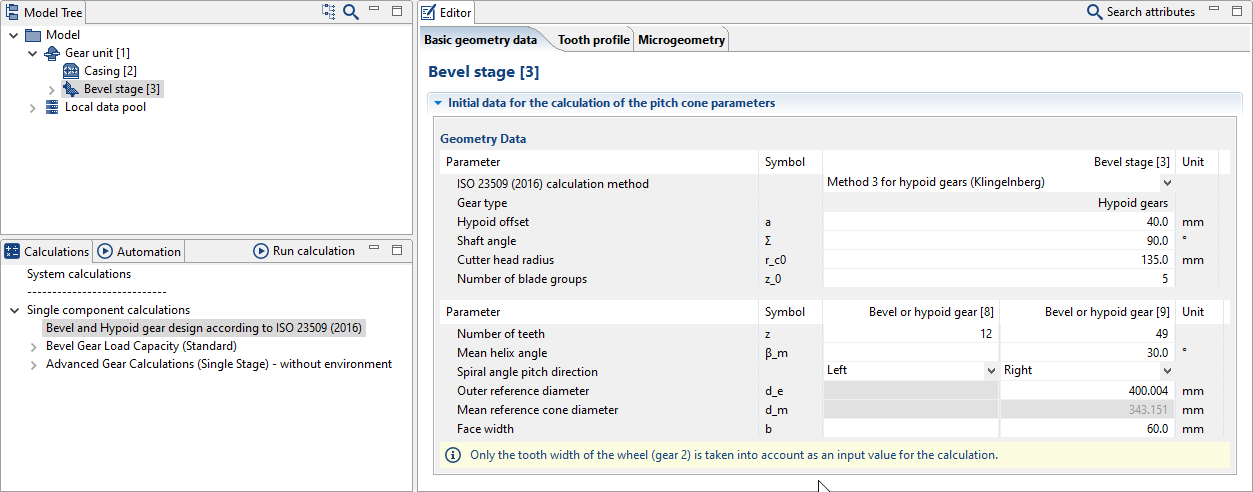
Basic geometry information
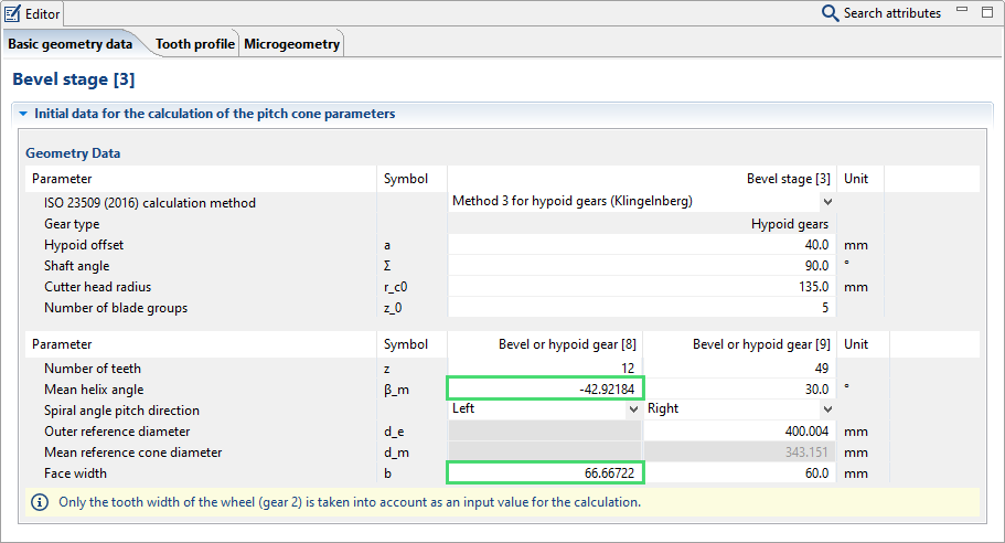
Select the bevel gear stage in the Model Tree and then choose calculations -> single component calculations -> geometry design according to ISO 23509 (2016). There are 3 separate tabs in the Editor for entering data. Start with the "basic geometry data" tab, and enter the parameters as shown.
Tip
For more information on the different design methods, see the attribute help
 for the attribute "ISO 23509 (2016) calculation method" in the basic geometry tab.
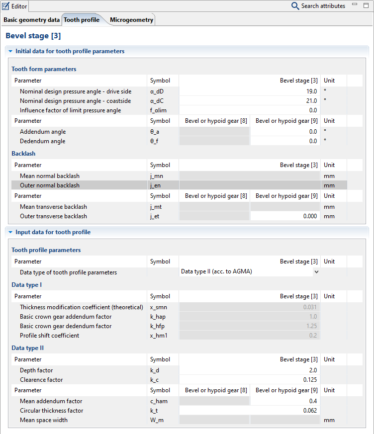
Tooth profile information
Change to the "tooth profile" tab in the Editor and enter the parameters as shown.
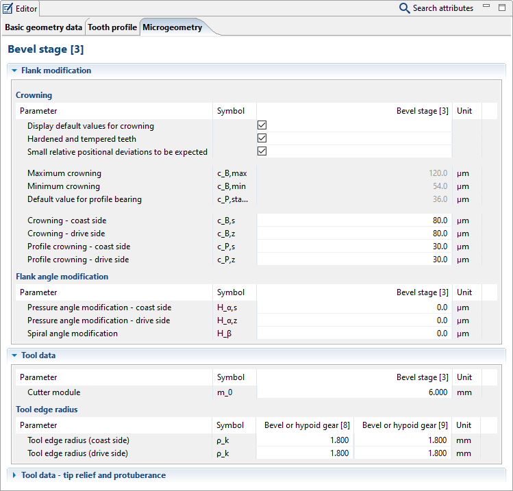
Microgeometry information
Change to the "microgeometry" tab in the Editor and enter the parameters as shown. Activate "show default values for crowning" and set the heat treatment and operating conditions as desired. For orientation, the corresponding default values for the profile crowning and, once the cutter module has been specified, depth crowning are shown as intervals or standard values.
Start the calculation
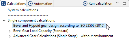
To start the pre-dimensioning calculation, select the bevel gear stage in the Model Tree and double-click "bevel and hypoid gear design according to ISO 23509 (2016)" under the calculations tab.
Results
Under the "basic geometry" tab in the Editor, you can see that the values for "mean helix angle" and "face width" have been calculated.
Notice
To export the machine settings data, right-click on the bevel gear stage and choose "Export Standard.KGD."
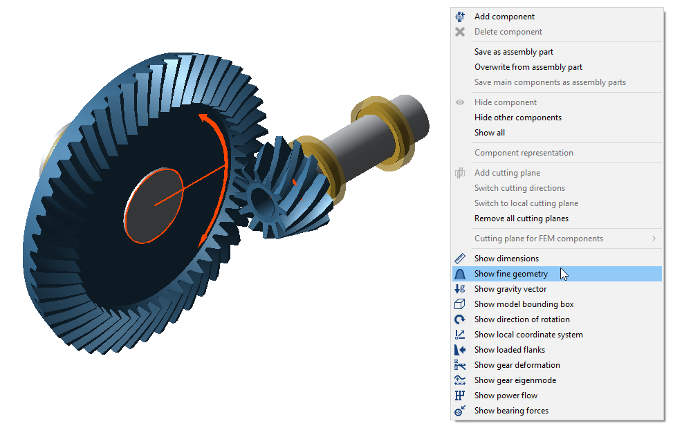
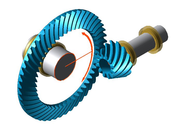
Now that the geometry has been calculated, it can be shown in the 3D View
 . Right-click in the 3D View and select "show fine geometry."