Shaft-in-shaft bearings
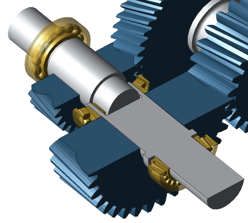
The following tutorial describes the modeling of shaft-in-shaft bearings.
The following files are needed to follow along with this tutorial in the FVA-Workbench:
Modeling
Load the shaft_in_shaft.wbpz gearbox model:
Project -> Open
Add a cylindrical stage
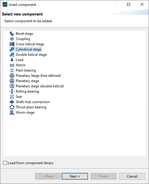
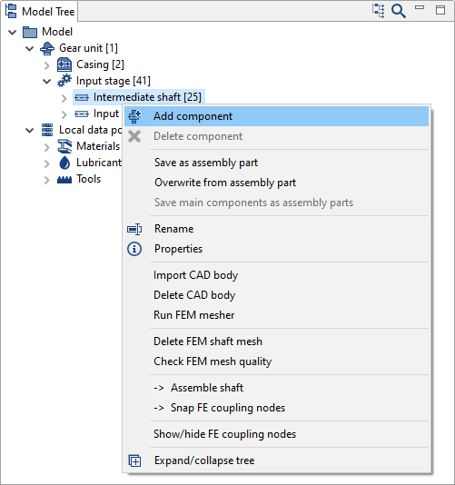
Right-click on "intermediate shaft" in the Model Tree and add a new cylindrical stage component.
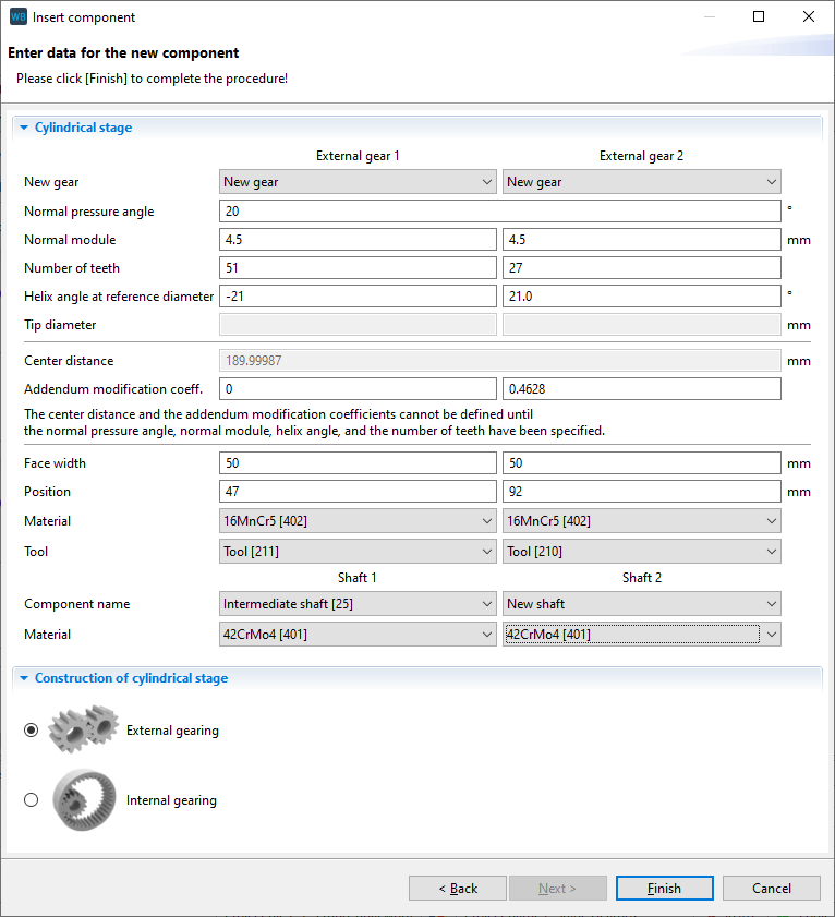
Specify the gear data
Enter the gear and material data according to the image. The first gear will be positioned on the existing shaft. A second shaft will automatically be created for the second gear.
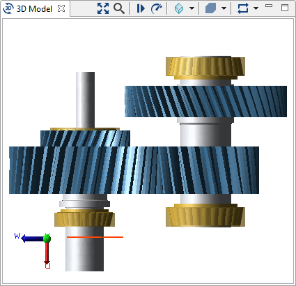
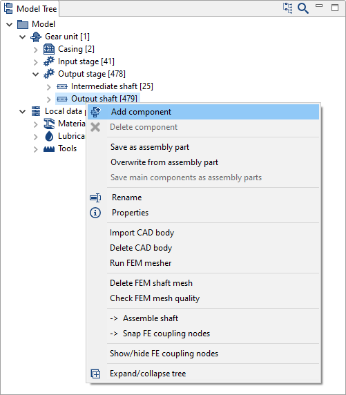
A new shaft is automatically created for the new cylindrical stage. This shaft has not yet been positioned and has no contours. Right-click on the components in the Model Tree to rename the new stage to "output stage" and the new shaft to "output shaft."
Specify the shaft contour and position
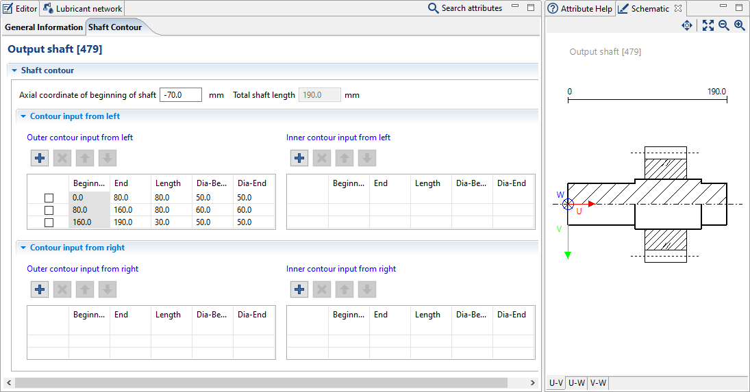
Select the "output shaft" in the Model Tree and choose the shaft contour tab in the Editor. Click + to add 3 new shaft sections and specify the length and diameter according to the image below.
Set the axial coordinate of the beginning of the shaft to -70mm.
Add the outer rolling bearings
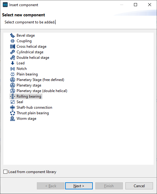
Right-click on the output shaft in the Model Tree to add a rolling bearing.
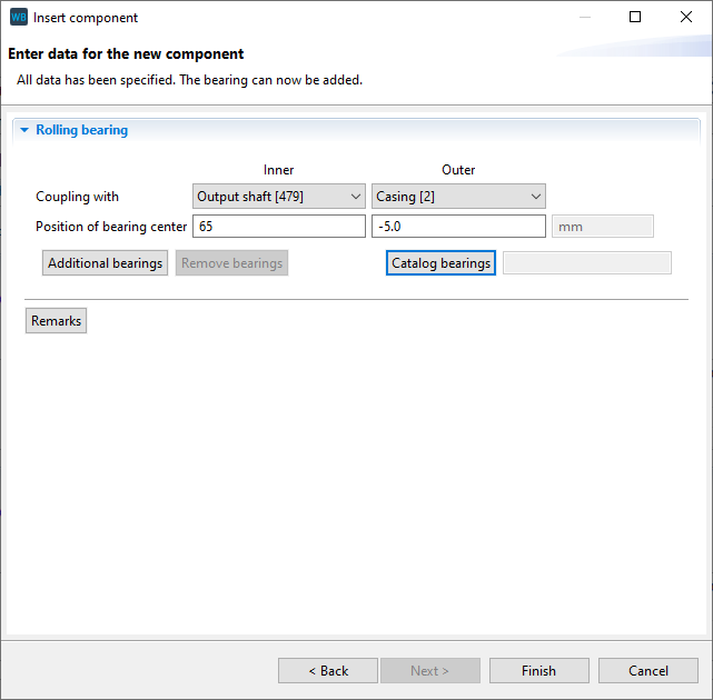
Couple the bearing inner ring with the output shaft and the outer ring with the casing. Enter 65 for the position of the inner ring. The position of the outer ring will be calculated automatically.
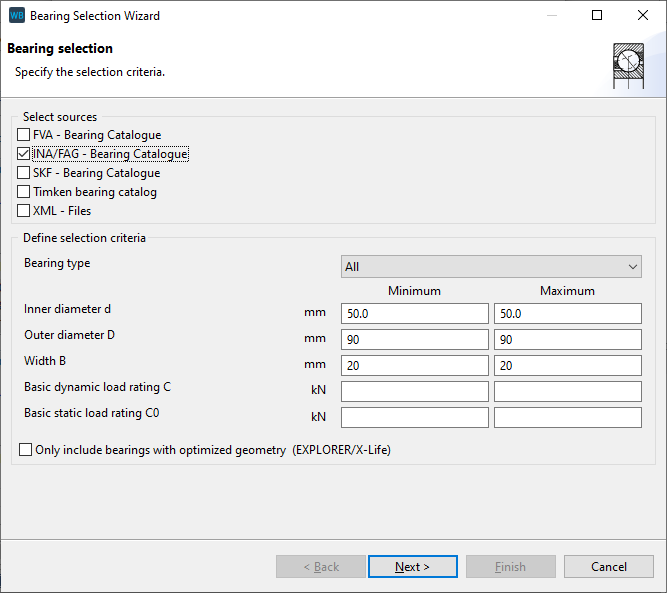
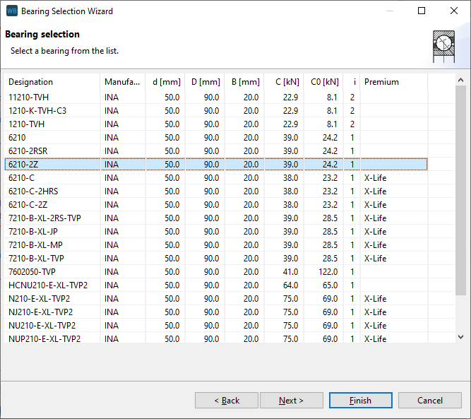
Now, click on "catalog bearings" and enter the search criteria as shown in the image below. Select the bearing 6210-2Z and click "finish" to close the dialog.
Add the inner rolling bearings
Add an additional rolling bearing on the output shaft as shown in step 5, above.
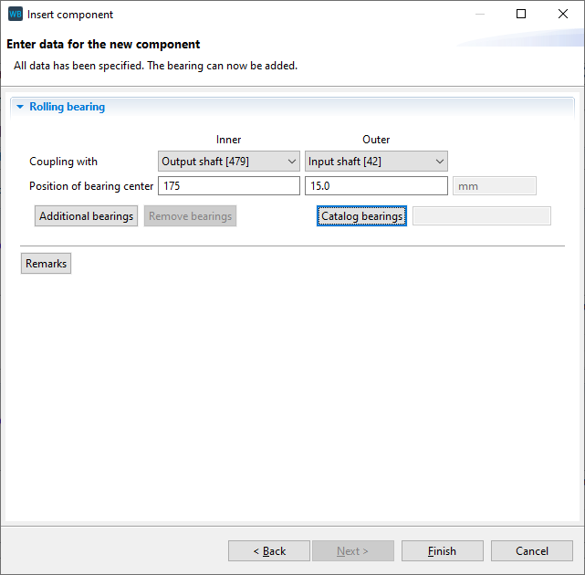
This bearing should sit between 2 shafts. Couple the inner ring with the output shaft and the outer ring with the input shaft. Enter 175mm for the position of the inner ring.
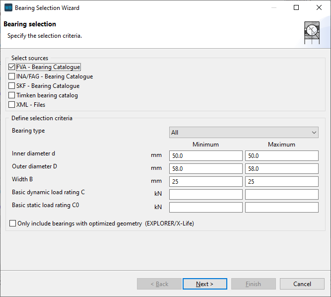
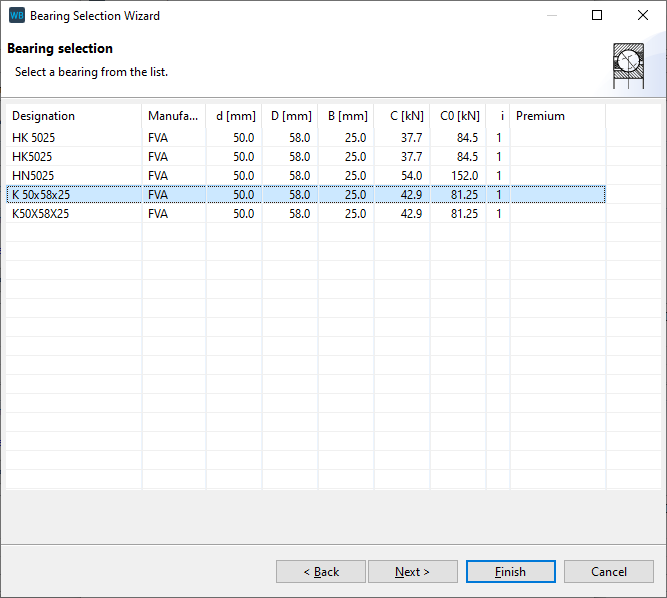
Now, click on "catalog bearings" and enter the search criteria as shown in the image below. Select the bearing K 50x58x25 and click "finish" to close the dialog.
