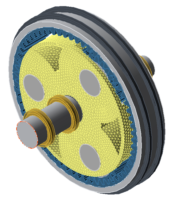
Parametric FEM planet carrier
The following tutorial will demonstrate the modeling, meshing, and calculation of a parametrically generated FEM planet carrier.
Modeling the planetary stage
Create a new model
 (Project → New)
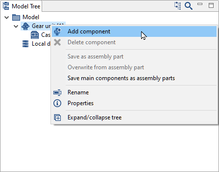
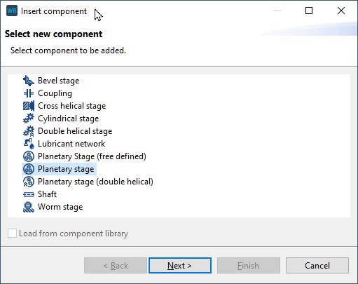
Add a planetary stage
Right-click on the gear unit in the Model Tree and add a new planetary stage component.
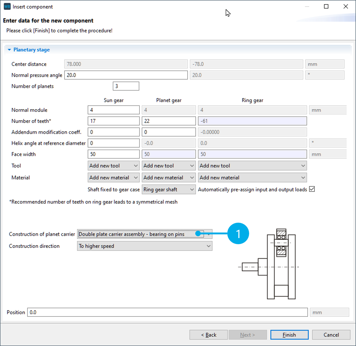
Specify the gear data
For "construction of the planet carrier," select option (1): "double plate carrier assembly - bearing on pins." The other gear data does not need to be changed.
Specifying the parameters for the struts
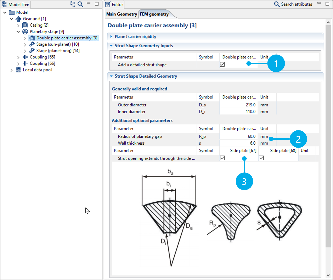
Add and edit the strut geometry
Select the planet carrier component in the Model Tree and change to the FEM Geometry tab. Activate specification of the gear geometry (1). Adjust the "radius of planetary gap" and "wall thickness" (2) as shown in the image. Activate the "strut opening extends through the side-plate" option (3).
Meshing and calculating the stiffness
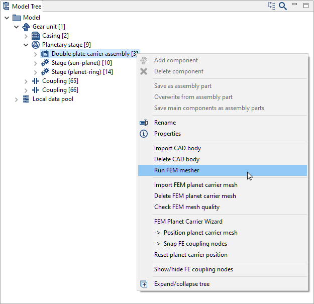
Start the mesher
Right-click on the planet carrier in the Model Tree to start the mesher.
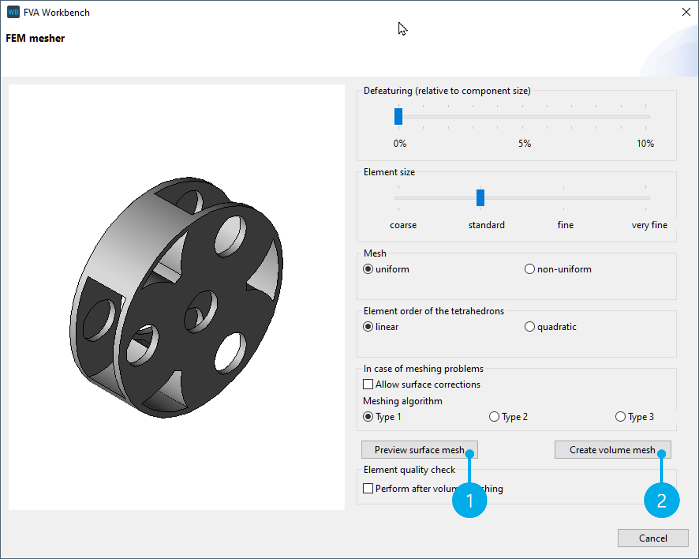
Meshing parameters
You can choose any meshing parameters you like for this tutorial. Click "preview surface mesh" (1) for a visual preview. If the surface mesh meets your requirements, click "create volume mesh" to complete the meshing.
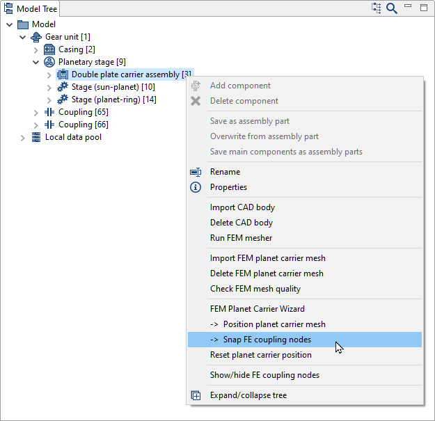
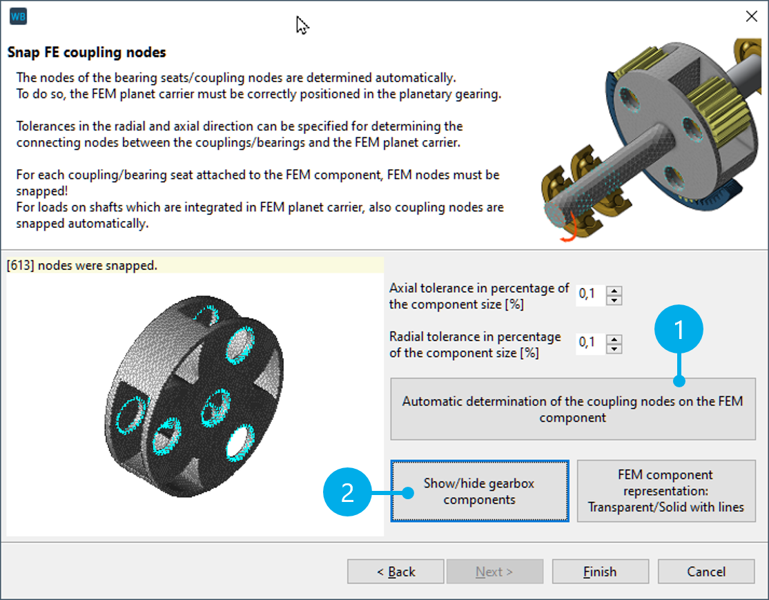
Snap the coupling nodes
Right-click on the planet carrier in the Model Tree and select "snap FE coupling nodes."
Click (1) to automatically snap the coupling nodes between the FE planet carrier and the analytical gear. Click (2) to hide the gear unit and check the snapped bearing nodes.
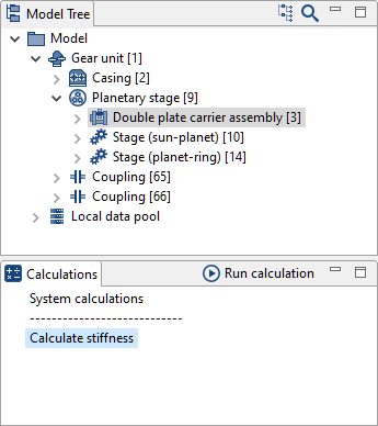
Calculate the stiffness
Select the planet carrier in the Model Tree and double-click "calculate stiffness."
Notice
Once calculated, the stiffness matrix is saved in the gear model (.wbpz). It does not need to be calculated every time the model is loaded.
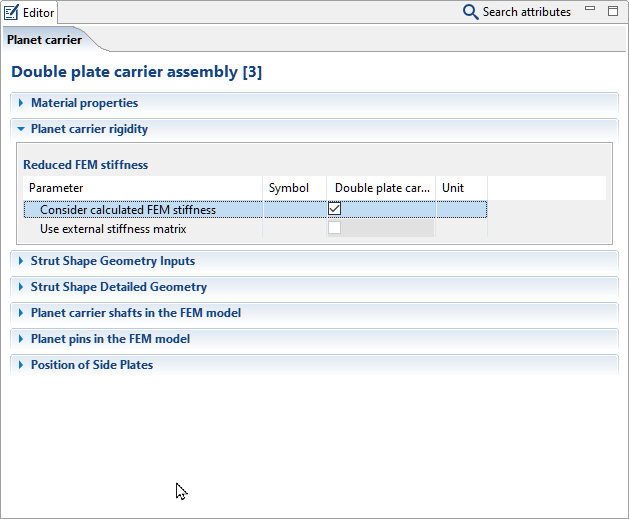
Consider the stiffness in the overall system
Check "use external stiffness matrix."
The deformation of the planet carrier is now considered in the system calculation.
Notice
If the stiffness is not considered, the planet carrier will be hidden in the 3D model and a warning message will be shown.