Braced drivetrains
In braced drivetrains, part of the power transmitted in the gear meshes circulates within the gearbox and is not transferred from the input to the output. This type of system is used in drivetrains in which zero backlash is important, or in test benches in which the reference torque is applied by the bracing and only the power loss is transmitted by the drivetrain. The bracing is typically applied using mechanical or hydraulic load clutches.
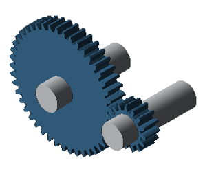
The following simplified model will be used to demonstrate how to represent braced drivetrains in the FVA-Workbench.
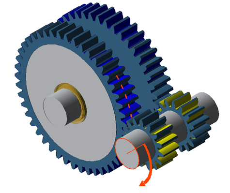
Example model of a braced drivetrain
Modeling the first cylindrical stage
Create a new model (Project → New)
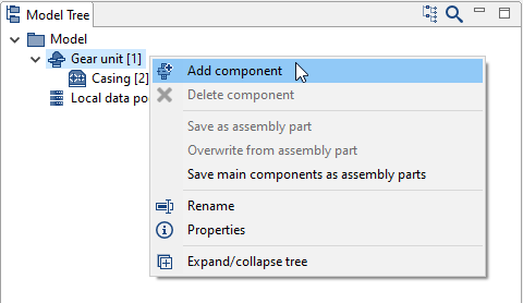
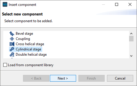
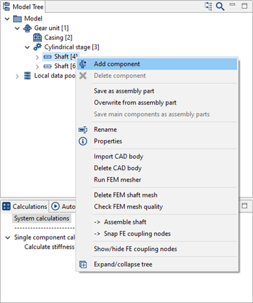
Right-click on the gear unit in the Model Tree, choose "add component," and then select "cylindrical stage."
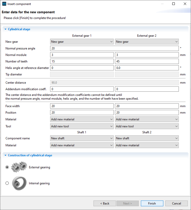
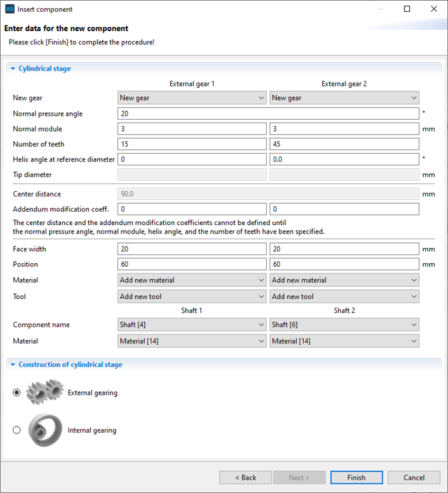
Change the position of the gears in the wizard as shown below. New shafts will automatically be created for Gear 1 and Gear 2.
Modeling the second cylindrical stage
Right-click on the first shaft in the Model Tree, choose "add component," and then select "cylindrical stage."
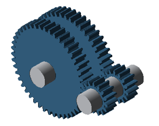
Change the position of the gears according to the image. Select the output shaft as the shaft for Gear 2.
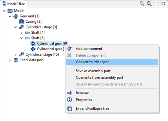
Converting cylindrical gears to idler gears
Right-click on Gear 2 of the 1st cylindrical stage to convert it to an idler gear.
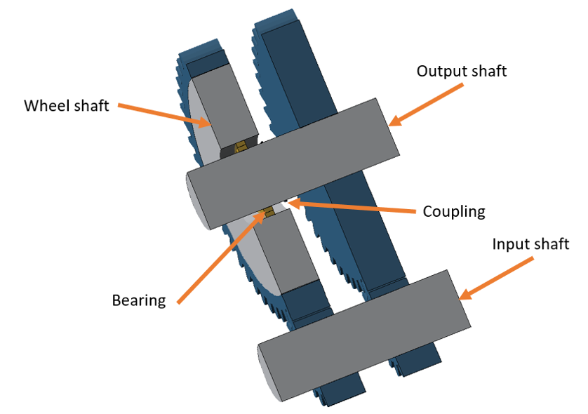
Notice
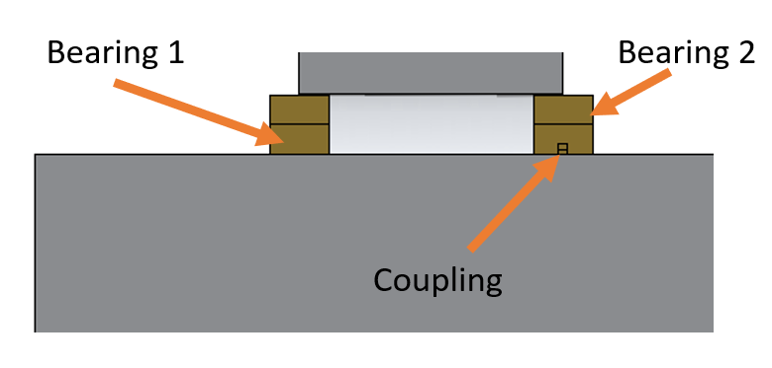
When the cylindrical gear is converted to an idler gear, it is positioned on a newly created auxiliary shaft which approximately corresponds to the wheel body.
A rolling bearing and coupling are added between this auxiliary shaft and the original shaft for transmitting the supporting forces and moment. The torque is transferred by the coupling.
In this case, the transmission of torque by the coupling must be deactivated in the switching matrix of the power flow editor.
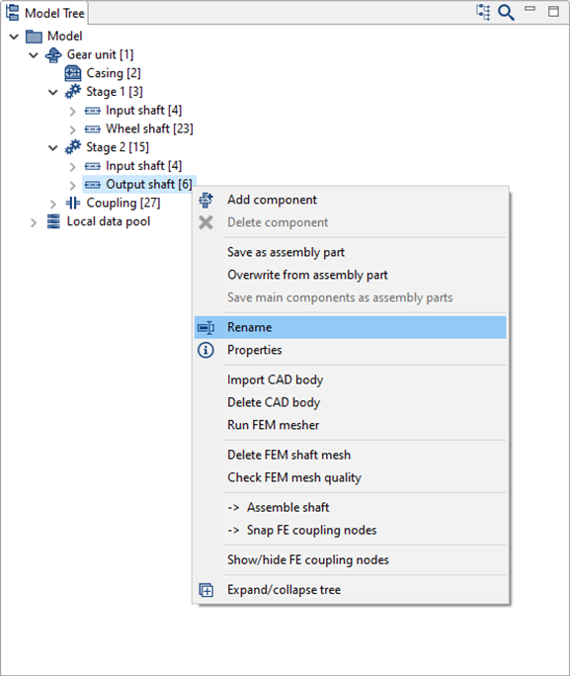
Right-click and rename each component as shown in the image.
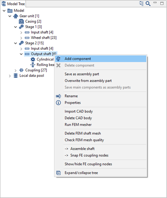
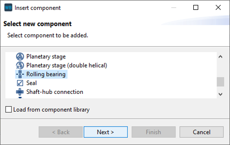
Right-click on the gear wheel shaft in the Model Tree and add a rolling bearing component.
Set the position of the bearing to be added as shown below.
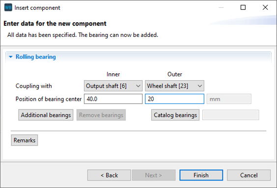
Set the position of the first newly created bearing according to the image below.
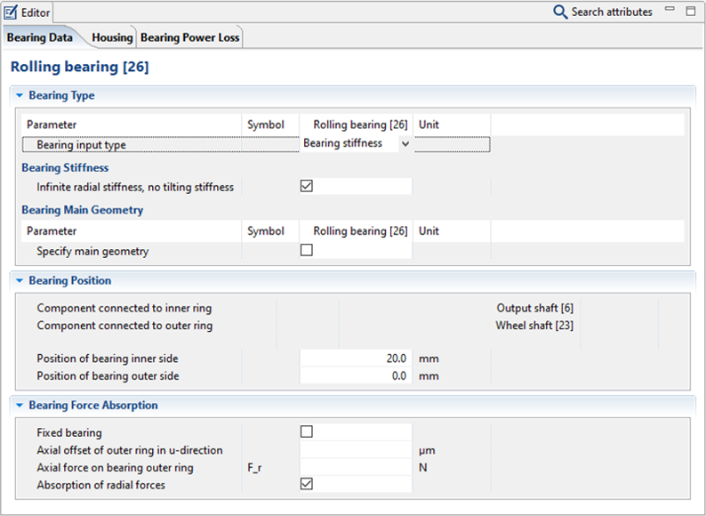
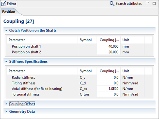
Change the stiffness of the coupling between the output shaft and the gear shaft according to the image.
Defining the power flow
Click  in the power flow editor to add the following load components to the gear unit:
1x load component on the drive shaft; this represents the drive torque of the gear unit.
2x load components on the output shaft. The moment at the end of the shaft is the output torque of the gear unit. This is automatically calculated. The moment under Gear 2 of the first stage is the load torque that is applied to the second stage of the gear unit.
1x load component on the wheel shaft. The moment on the wheel shaft is the moment which acts against the load torque, which is applied to the first stage.
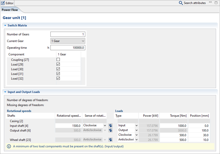
As described previously, the torque transmission of the coupling must be deactivated in the switching matrix.