Load spectra
Using load spectra in the system calculation
To consider load spectra in the system calculation, "consider load spectrum" must be activated in the calculations tab under the gear unit.
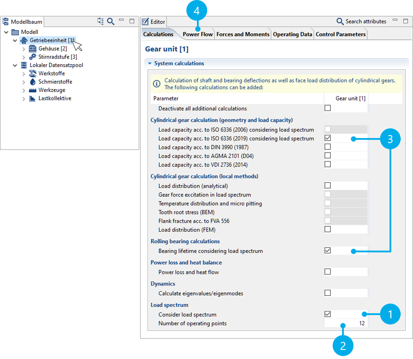
(1) Activates the load spectrum calculation in the system calculation.
(2) Number of points within the specified load spectrum for which the system will be solved.
(3) Calculations in which the load spectrum is considered have "load spectrum" in their name.
(4) The selection of the load spectra per gear and the distribution of the total lifetime is made in the "Power Flow" tab.
Number of points calculated in the load spectrum
The system calculation is performed for each load and speed stage. Thus, the influences from the load (such as the face load distribution) and the speed (such as the lubricant film thickness) valid for these stages are taken into account in all stages of the load spectrum. In order to reduce the calculation time for large spectra, the number of operating points for which the system calculation is solved can be specified. These operating points are distributed evenly in the spectrum. For all other load spectrum levels, the loads and speeds are interpolated and the corresponding damage fractions and lifetimes are calculated. If the number of load points is greater than or equal to the number of stages selected in the load spectrum, all stages are calculated in the system calculation.
Notice
When specifying only a speed spectrum, two different calculation options are available. If the torque is specified in the power flow definition of the gearbox, this is kept constant and only the speed is varied. If the gearbox power is specified, the torques in the load stages are adjusted so that the power remains constant.
Specifying a load spectrum and time shares
In the load spectrum calculation, an individual load spectrum can be specified for every gear in the gear unit. The required settings can be made in the Power Flow tab of the gear unit component.
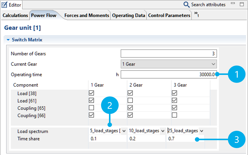
(1) Specification of the total gear unit service life.
(2) A load spectrum can be selected from the Global Database for each gear.
(3) Distribution of the total service life to the individual gears.
Time shares are used to distribute the specified total service life of the gear to the individual gears. Weighting factors are specified, and a time share is calculated from the weighting factor divided by the sum of all weighting factors multiplied by the total service life. Thus, the time shares can be entered as percentages, factors, or hours. The following entries lead to the same result:
Total number of hours: 30,000 | ||||
Gear | Factor | Factor | Percent | Hours |
|---|---|---|---|---|
Gear 1 | 0.1 | 2 | 10 | 3000 |
Gear 2 | 0.2 | 4 | 20 | 6000 |
Gear 3 | 0.7 | 14 | 70 | 21000 |
If existing percentage or hourly weighting factors are used, the sum does not need to correspond to 100 % or the total number of hours. If the specified total number of hours in the table above was not 30,000 h but rather 60000 h, the individual time shares would be internally converted to 6000 h (Gear 1), 12000 h (Gear 2) and 42,000 h (Gear 3).
Calculation options
Load spectra can be considered in the following calculations in the FVA-Workbench:
Cylindrical gears
Tooth flank & tooth root load carrying capacity acc. to ISO 6336 Part 6:
Safety factor (spectrum) acc. to Miner
Static safety
Continuous safety
Various damage accumulation hypotheses can be selected
Stress collectives and Woehler S-N curves
Maximum permissible scaled total number of load cycles
Gear excitation
Excitation level over the load
Tooth force level over the load
Force amplitudes over the load
Excitation amplitude level over the load
Transmission deviation amplitudes over the load
Maximum transmission deviation over the load
Mean transmission deviation over the load
Bevel gears
Standard bevel gear calculation (standard calculation acc. to ISO 10300 (2014))
Comparison of variants for local calculations
Mean specific gear tooth stiffness
Velocity level at 1000 U/min
Efficiency
Double amplitude of the total working variation
Minimum safety against scuffing
Maximum Hertzian contact stress
Maximum flash temperature
Maximum tooth root stress
Minimum safety against pitting of the pinion
Minimum safety against pitting of the gear
Local damage accumulation (tooth root/tooth flank damage sum)
Rolling bearings
Rolling bearing lifetime (accumulated lifetimes)
Shafts
Strength calculation acc. to FKM (2012)
Creating load spectra
Load spectra are saved as data records in the Global Database. Load spectra saved in the database can be then be added to any gearbox model as a database component.
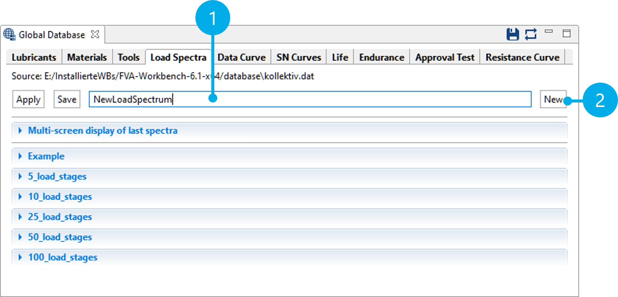
(1) Name of the new load spectrum
(2) Creates a new data record of the type load spectrum.
Importing load spectra as .csv
Load spectra can be imported as .csv files (comma-separated values). These files can be created in Excel or another spreadsheet program. The step frequency must be specified in the first column. Load amplitudes for torque and speed can be specified in the second and third columns. The load spectra can be single or double column. Optionally, the title of the data row can be specified in the first row.
Notice
Commas must be used as a decimal separator in the data series. The default decimal separator can be configured in Excel under file -> options -> advanced.
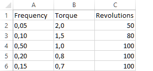
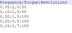
Load spectrum with 2 data rows for torque (factor) and speed (%). The file is shown in Excel on the left and as a .csv file in the text editor on the right.
- Figure 7. Import the example file
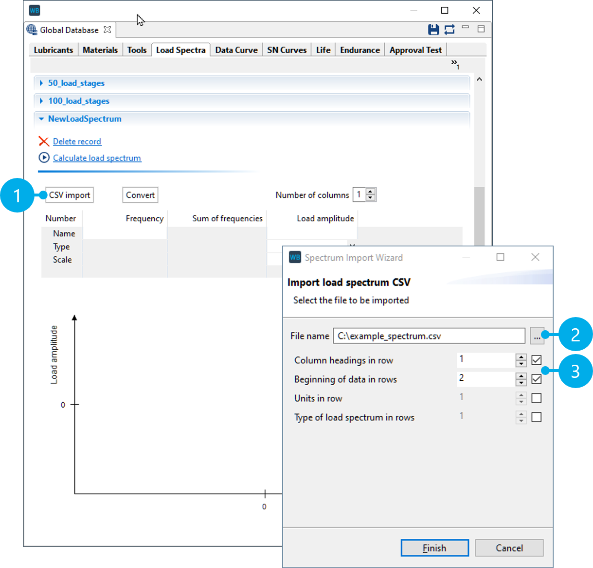
(1) Starts the .csv import
(2) Select the file
(3) Selection of which row includes the title and where the data series starts.
- Figure 8. Define the type and units of the data series
(1,2) After successful import, the type must be specified for each data series (torque/speed). It must also be selected whether the values are percentages (%) or factors (--).
(3) Once all information is complete, the data record can be saved in the Global Database.
Creating synthetic load spectra
Synthetic spectra can be useful in general investigations and preliminary design. They can be described mathematically using the three parameters spectrum scope H0, highest value Ŝa, and shape parameter ν. The larger the shape parameter ν, the greater the damage content of the synthetic load spectra with the same scope H0 and highest value Ŝa.
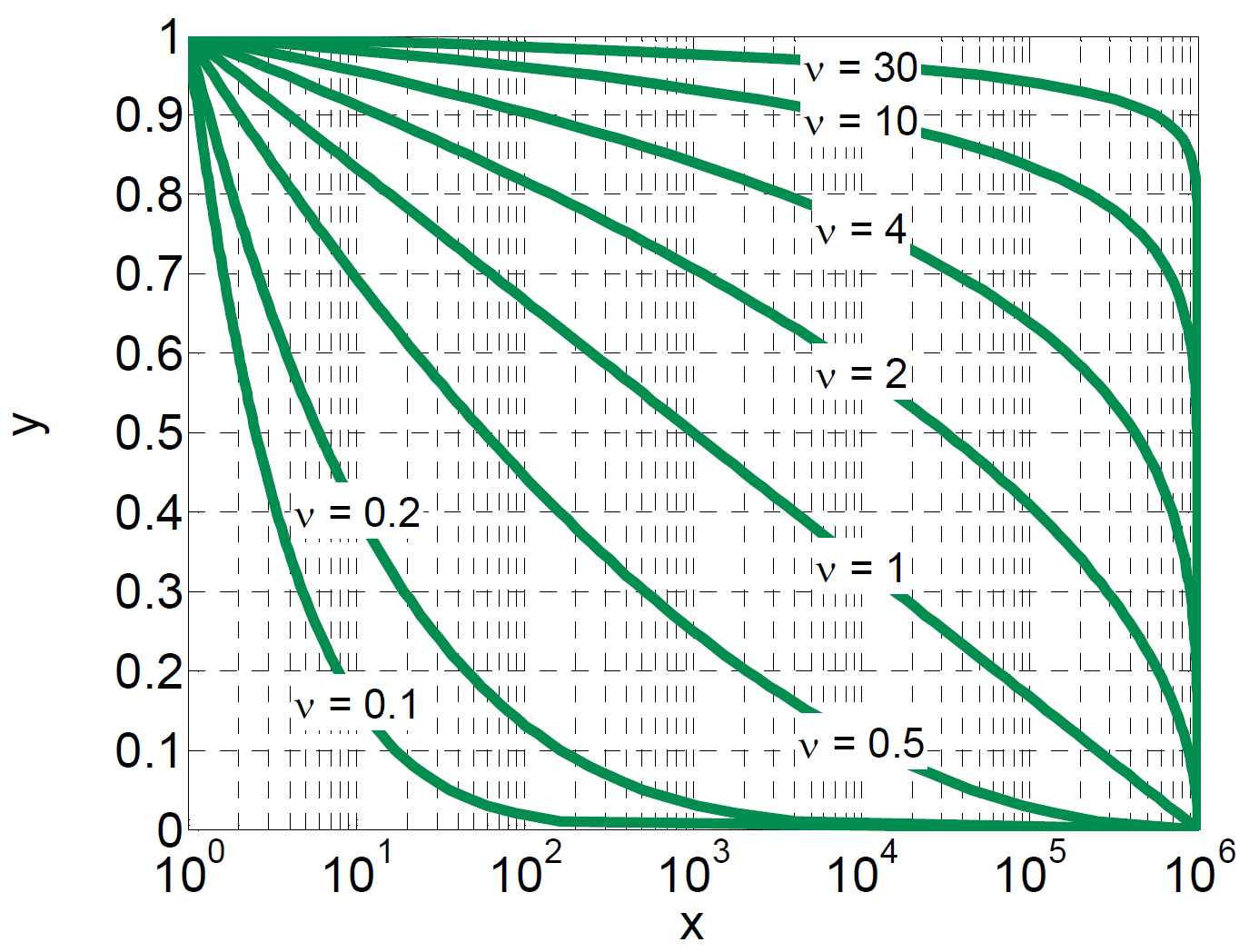
X axis: cumulative frequency H (log)
Y axis: amplitude, relative to the highest value of the spectrum
- Figure 10. Create a load spectrum
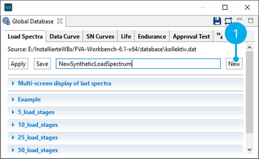
(1) Creates a new load spectrum
- Figure 11. Start the load spectrum calculation
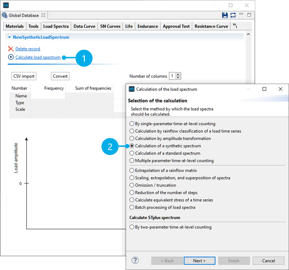
(1) Starts the load spectrum calculation
(2) Creates a synthetic load spectrum
- Figure 12. Specify the load spectrum parameters
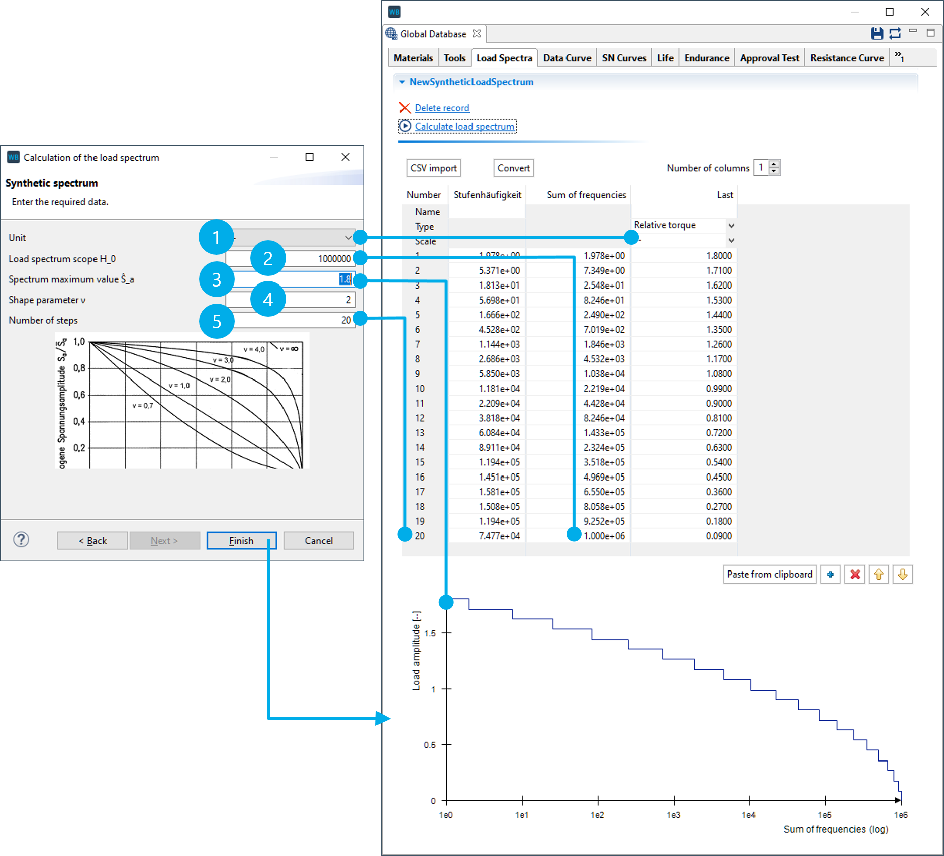
(1) Unit of the load amplitudes ("--" for factor)
(2) Number of load cycles
(3) Highest value of the spectrum (here, 1.8 x nominal torque)
(4) Shape parameter ν of the load spectrum
(5) Number of steps in the load spectrum