FEM in the FVA-Workbench
When analyzing complex transmission systems, it is extremely important to model the boundary conditions as accurately as possible. By coupling FEM structures with the analytical calculation model, it is possible to consider the influence of the gear casing, planet carriers, and complex shaft geometries on the overall system.
This allows for the targeted design of gear modifications, for example, taking the deformation behavior of complex components into consideration.
For bevel and cylindrical gears, the wheel body can be specified as an FEM structure. The deformation of the wheel body is not included in the overall system. However, the effects of the deformation can be considered at the stage level.
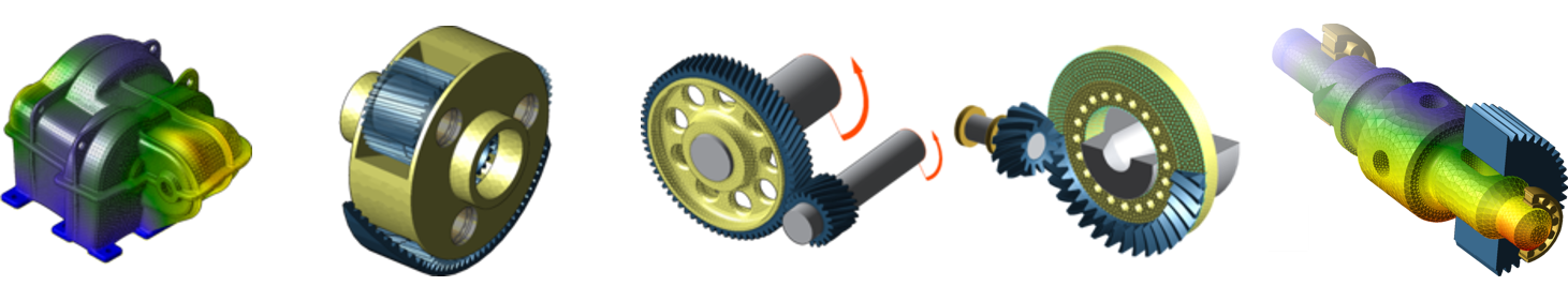 |
Gearbox casings, planet carriers, cylindrical and bevel gear wheel bodies, and shafts can be considered as FE components.
 |
Different methods for integrating FEM structures in the FVA-Workbench
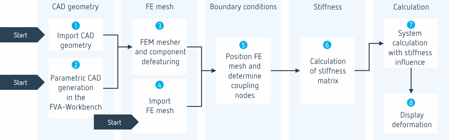
An interactive assistant is provided in the FVA-Workbench to assist with the steps of coupling FE structures with the analytical model and subsequent calculations.
In the first step, a CAD file can be imported (1). Optionally, planet carriers and shafts can be parametrically modeled directly in the FVA-Workbench (2). This allows the stiffness to be considered in a high level of detail early in the design phase with minimal effort.
The CAD geometry can be automatically meshed in the second step. Parameters such as the meshing size, element type, and component defeaturing can be adjusted (3). Alternatively, an FE mesh can be imported directly from a third-party application (4).
In the next step, the FEM component is positioned so that the bearing seats or the bores are precisely aligned with the FVA-Workbench analytical model. For wheel bodies, the CAD geometry is automatically fit to enable correct connection to the gear. The coupling nodes between the mesh and the analytical model as well as the fixing nodes of the casing are also determined (5) .
Finally, the reduced stiffness matrix is calculated (6), which considers the stiffness of the FEM component in the system calculation. The matrix only needs to be determined once; recalculation is only necessary if the material data or coupling points are changed.
 [de] FEM in der FVA-Workbench Teil 1 Getriebegehäuse [German] | [de] FEM Planet Carrier: Modeling and Best Practices | [de] Wheel Body Design |
File formats
Mesh formats
The Z88 and Abaqus *.INP meshing formats are currently supported.
Z88 is the native file format of the free Z88 finite element analysis program, which has been developed by the University of Bayreuth since 1986.
Other FE structure data can be converted to the Z88 format with the open source Z88Aurora program. The following FE mesh formats are supported by Z88Aurora:
Nastran (.NAS)
Abaqus (.INP)
Ansys (.ANS)
Cosmos (.COS)

CAD formats
The following CAD formats can be imported:
STEP (.step)
CATIA V5 (.CATPart)
Pro/E (.prt)
Solid Edge (.par)
Solid Works (.sldprt)
Inventor (.ipt)
Siemens NX (.prt)
Mesher
The FEM mesher in the FVA-Workbench makes it possible to generate FEM meshes from CAD geometry in just a few steps. The CAD geometry can be directly imported or, in the case of planet carriers and shafts, parametrically generated internally. The simple and intuitive user interface simplifies the creation of FEM meshes.
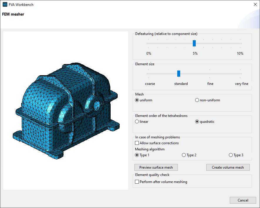
Various meshing parameters can be specified in the meshing dialog.