FEM gearbox casings
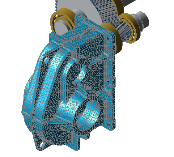
The following tutorial will use the example of a single-stage industrial gearbox to demonstrate the import and positioning an FEM gearbox casing. Next, the reduced stiffness matrix will be determined and the resulting component deformation will be calculated and displayed.
The following files are required to follow along with this tutorial in the FVA-Workbench:
Import and positioning
Load the gearbox model fem_housing.wbpz:
Project -> Open
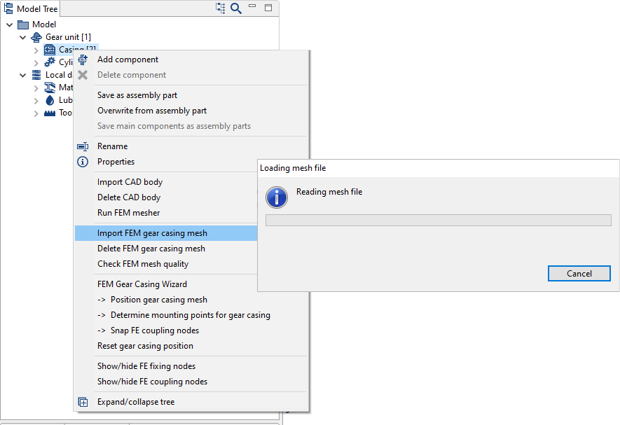
Load the casing mesh file fem _housing.z88i1:
Right-click on the casing components in the Model Tree in the FVA-Workbench -> Import FEM gear casing mesh -> Select mesh file
Confirm mm as the unit for the gearbox design. The casing is initially positioned in space independent of the gearbox model.
Right-click on the casing in the Model Tree and select "FEM Gear Casing Wizard " to start the step-by-step assistant.
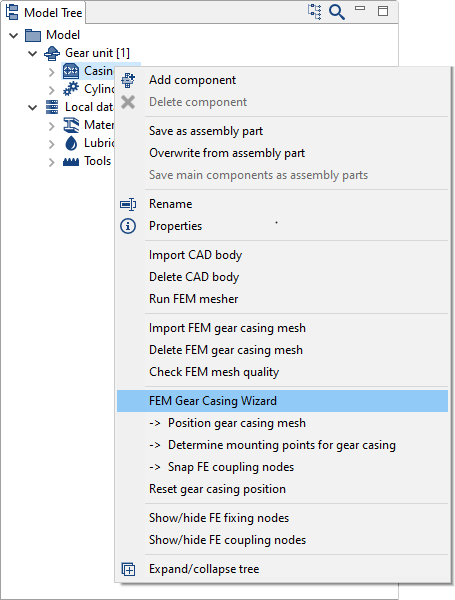
The assistant will perform the following steps in succession:
1. Align the casing axes to the shafts
2. Determine the bearing contact surfaces
3. Determine the foundation nodes
4. Determine the nodes of the bearing seats
Align the casing axes to the shafts - first shaft
Align the shaft [7] to the corresponding casing axis.
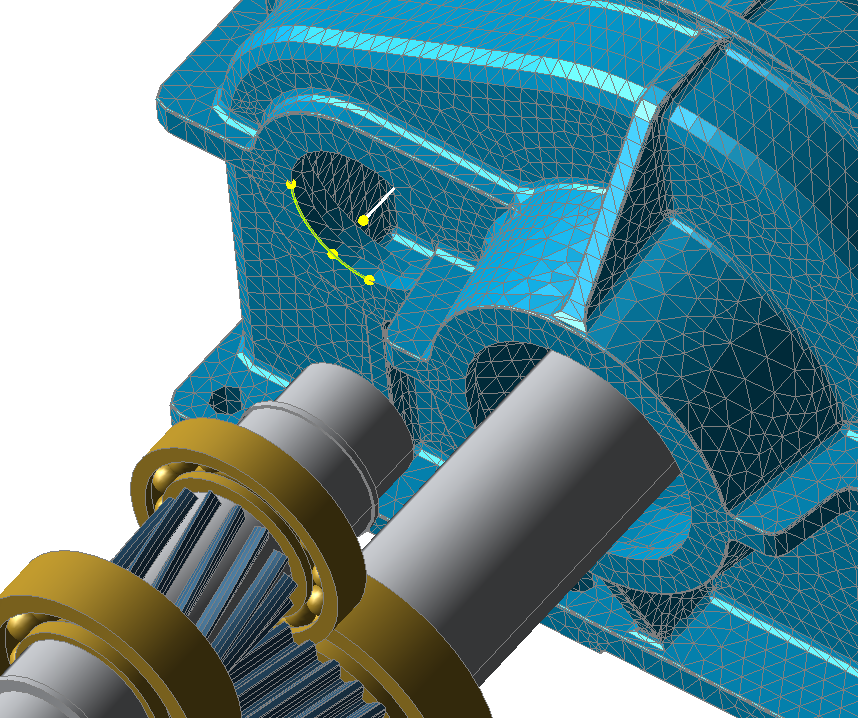
Select the reference shaft (shaft [7]) and select the node points on one of the two bearing seats.
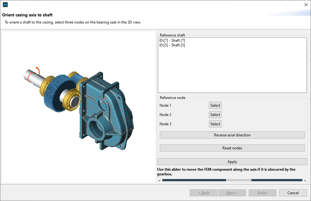
For orientation: The bearing seats of shaft [7] have the larger diameter.
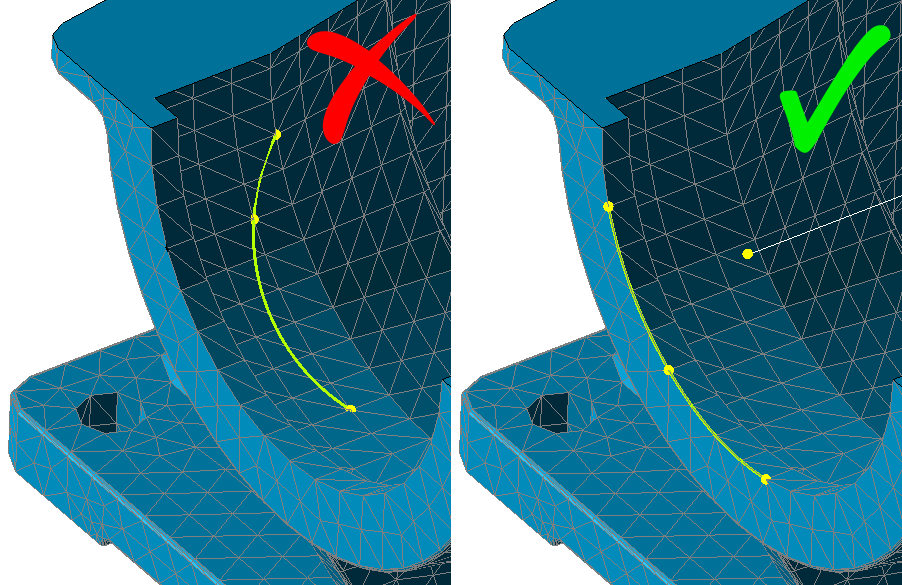
Notice
The 3 nodes span a plane whose midpoint corresponds to the midpoint of the shaft axis. Select points along the edge of the bearing seat.
If the gearbox is mounted the wrong way around in the casing, the direction of the axis can be reversed.
If the gearbox covers the casing, the distance between the gear unit and the casing can be varied with a slider. This feature is only to provide a better overview, it has no influence on the positioning.
Click "position" to align the reference shaft. The reference shaft can also be changed after the node points have been determined. The other shaft will then automatically be centered on the casing axis. Click "next" to complete the positioning of the first shaft.
Align the casing axes to the shafts - second shaft
The reference shaft which has already been positioned is hidden. Click "next" to complete the positioning of the second reference shaft.
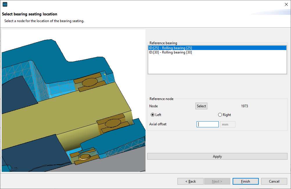
The axial position of the shafts in the casing is determined in the next step. The contact surface of a bearing can be used as a reference point. The bearings of the shaft that was positioned first are always available as reference bearings (here: shaft [7]).
Notice
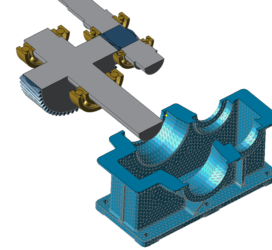
Right-click on a shaft to create a cutting plane through the casing to provide better visibility of the contact surface.
Select one of the individual nodes on the contact surface of the bearing. Use "left" and "right" to specify whether it is the left or right contact surface.
Nodes for defining the boundary conditions
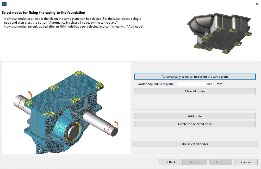
To define the connection of the casing to the foundation, individual nodes can be selected by hand or all nodes in a plane can be selected automatically.
In this example, the contact surfaces with the casing bores for bolting to the foundation are slightly raised. Therefore, all node points are on a single plane and can be selected automatically.
Select a node on one of the contact surfaces with a bore.
Click "automatically select all nodes on the same plane" to highlight all the nodes. Next, click "use selected nodes" and click "next" to complete the step.
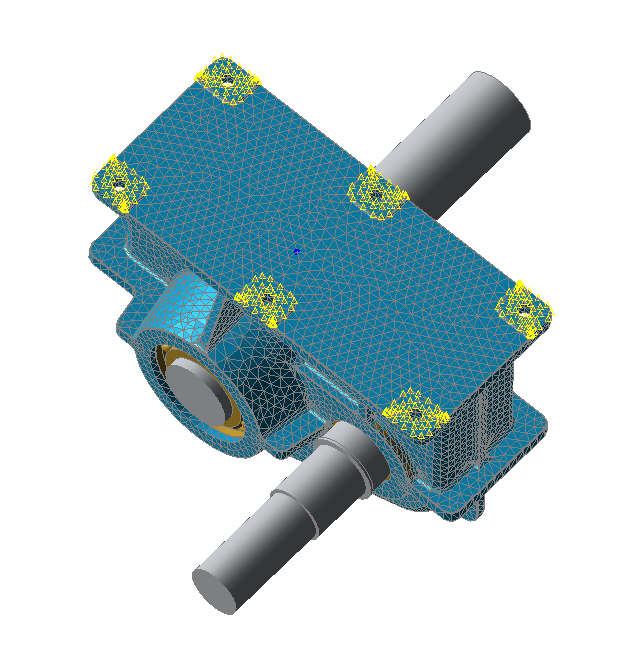
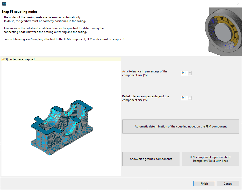
Snap FE coupling nodes
If the positioning is correct, all nodes that have a connection between the bearing seat and the bearing will be shown after clicking "Snap FE coupling nodes." If no points are shown, or only a few, correction is required.
Notice
Any inaccuracies in the mesh can be compensated for by adjusting the tolerance in the radial and axial direction. The greater the selected tolerance, the more nodes that are snapped.
If the gear unit is tilted in the casing, repositioning is required.
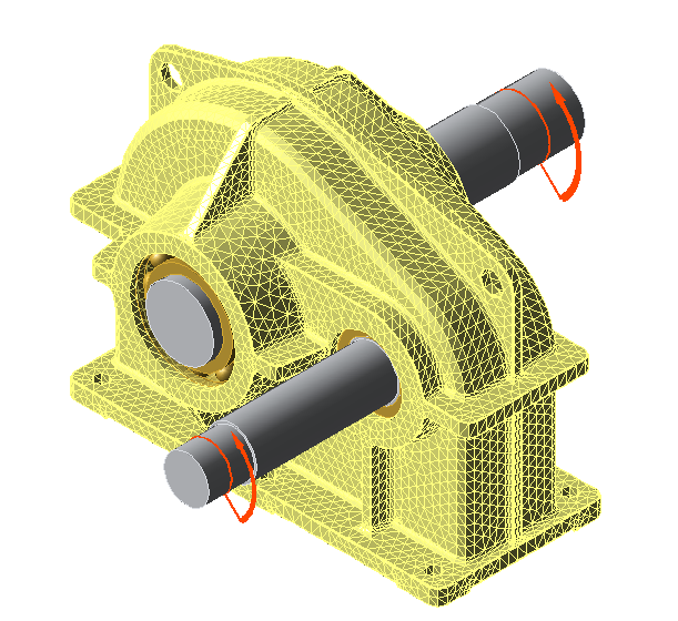
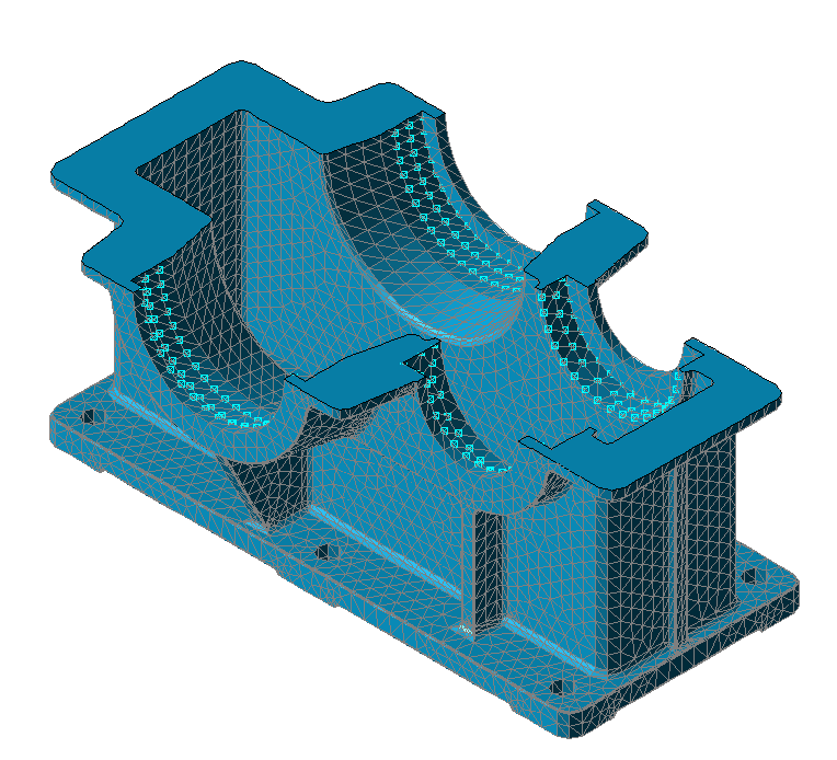
The gear unit can be hidden to check the snapped bearing nodes.
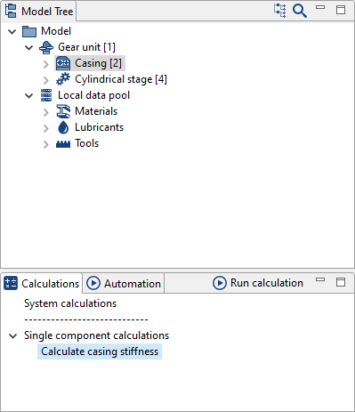
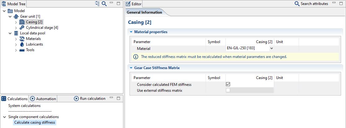
Calculating the stiffness
After the casing stiffness has been successfully calculated by running the "calculate casing stiffness" calculation, the resulting stiffness matrix is considered in the system calculation.
Notice
The reduced stiffness matrix is saved in the gearbox model (.wbpz) and does not need to be determined every time the model is opened.
The "consider calculated FEM stiffness" switch determines whether or not the stiffness matrix for this FE model is considered in the system calculation. If this switch is not selected, the FE model of the casing is hidden in the 3D view.
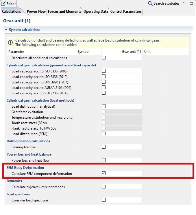
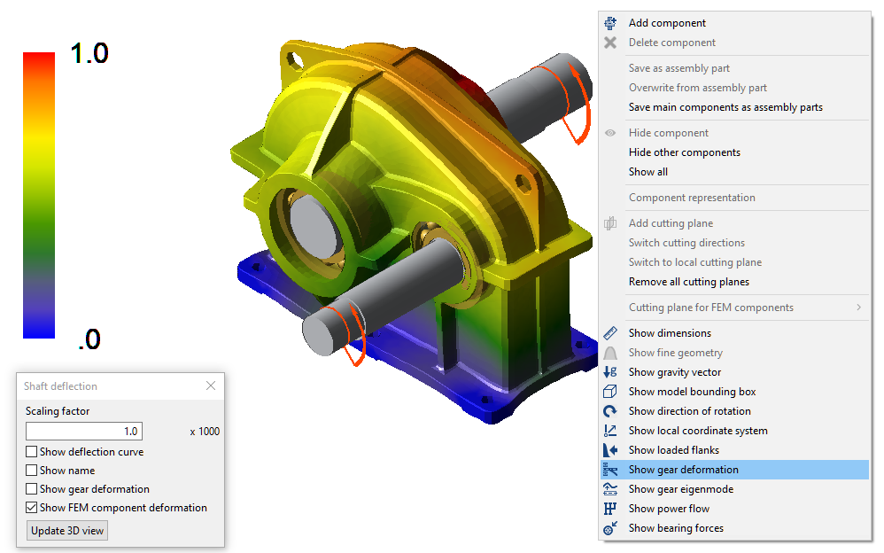
Calculating component deformation
To show the deformation of the casing in the 3D model, run a system calculation with the additional option "calculate component deformation." The deformation can be displayed by right-clicking in the 3D model -> "show gear deformation" -> "show FEM component deformation."