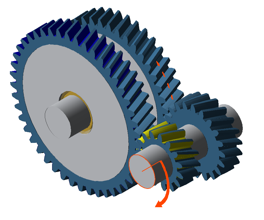
Modeling a switchable gearbox
Multiple gears can be defined in a switchable gearbox. The power is transmitted via a different path for each gear. The power paths are determined by a switch matrix, in which the coupling between the shafts and gears is engaged or disengaged. The following tutorial will describe the design of a gearbox with two gears.
Modeling
Create a new model
 (Project → New)
Add a cylindrical gear stage
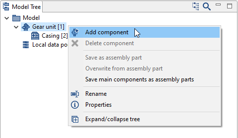
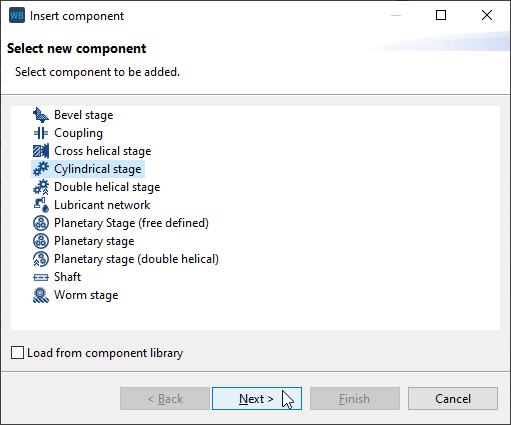
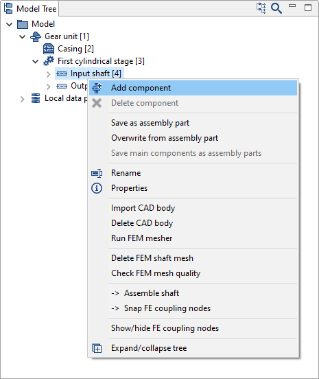
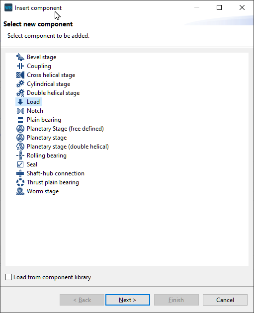
Right-click on the gear unit in the Model Tree, choose "add component," and select "cylindrical stage."
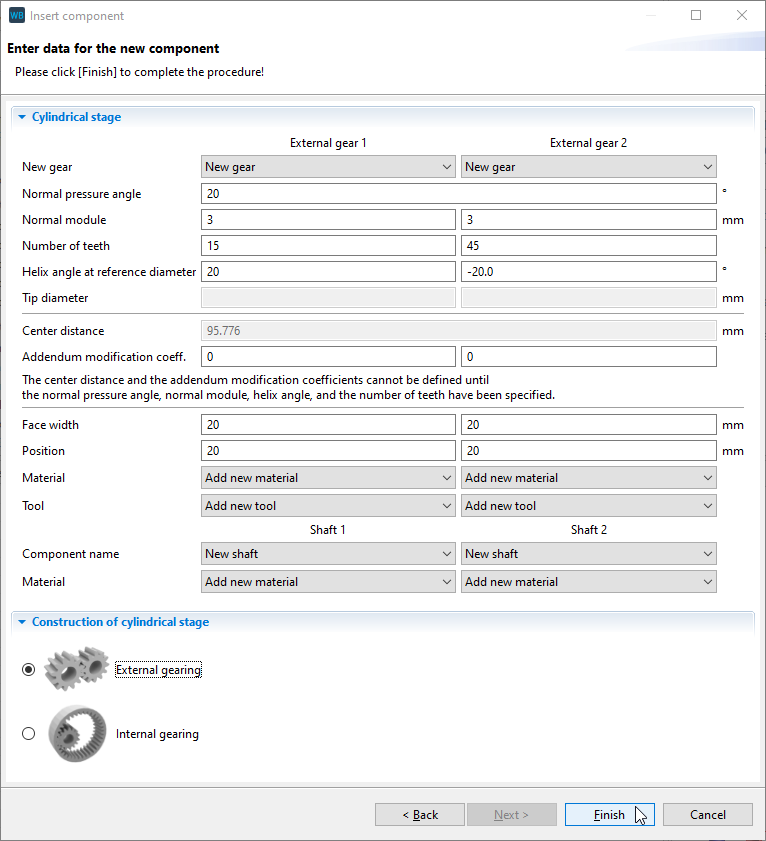
Specify the gear data
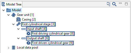
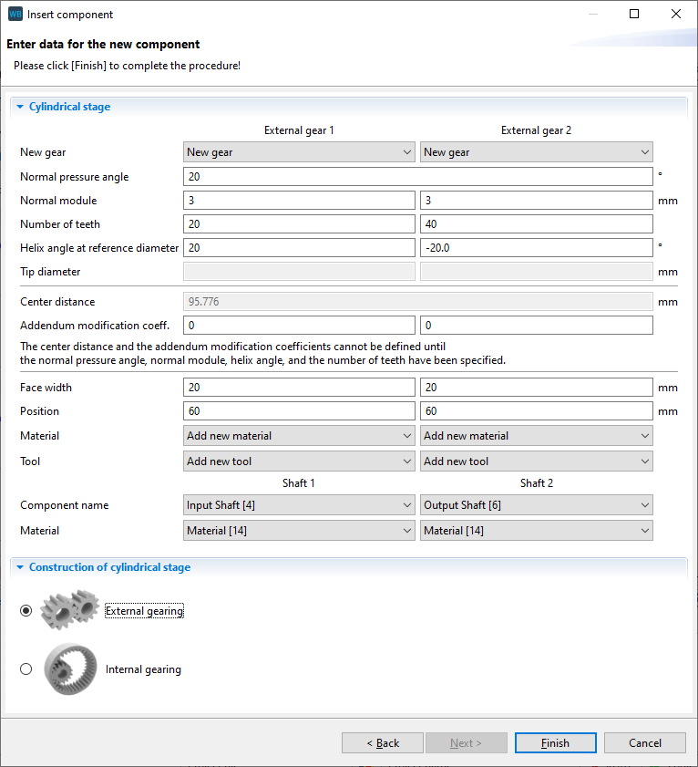
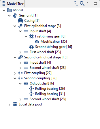
Enter the gear data and rename the new components in the Model Tree as shown below.
Add a cylindrical stage
Right-click on the input shaft in the Model Tree to add an additional cylindrical stage. Enter the gear data as shown below. Select "output shaft" as the shaft for the second gear.
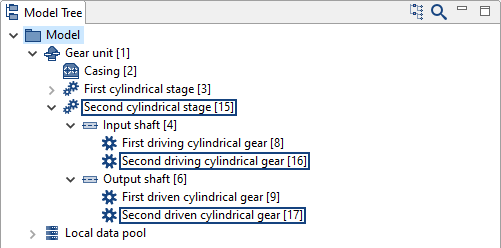
Rename the new components as follows.
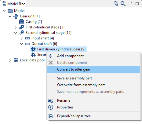
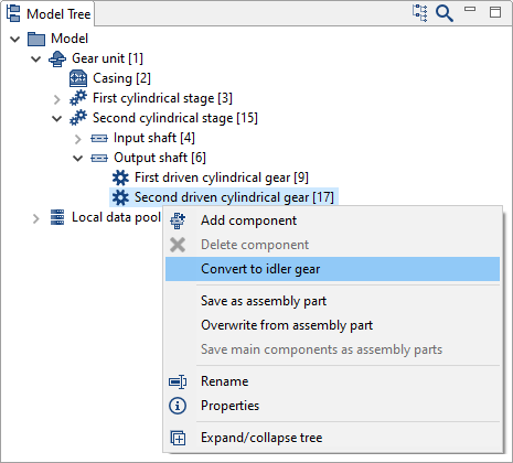
Convert the gears to idler gears
Right-click on both gears ("first driven cylindrical gear" and "second driven cylindrical gear") on the output shaft in the Model Tree and convert them idler gears. This will create two new bearings, shafts, and couplings located between the gears and the output shaft.
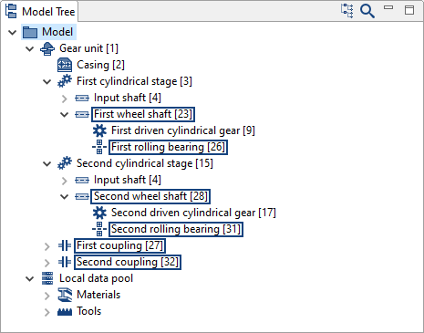
Rename the new components as follows.
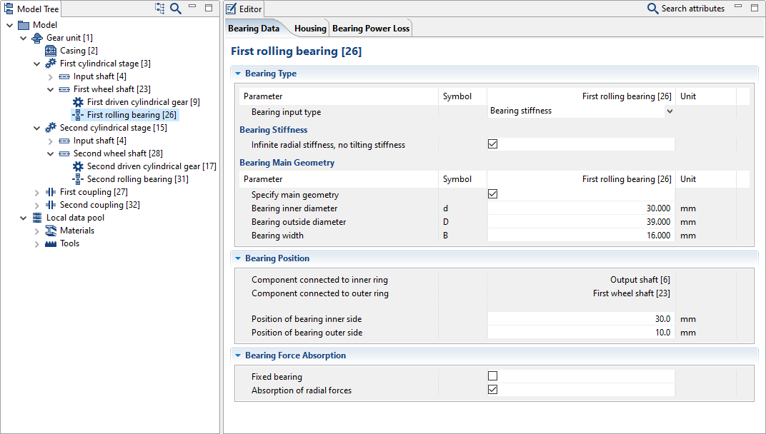
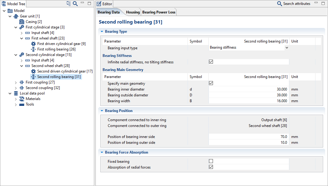
Specify the bearing data
Enter the bearing data as shown below.
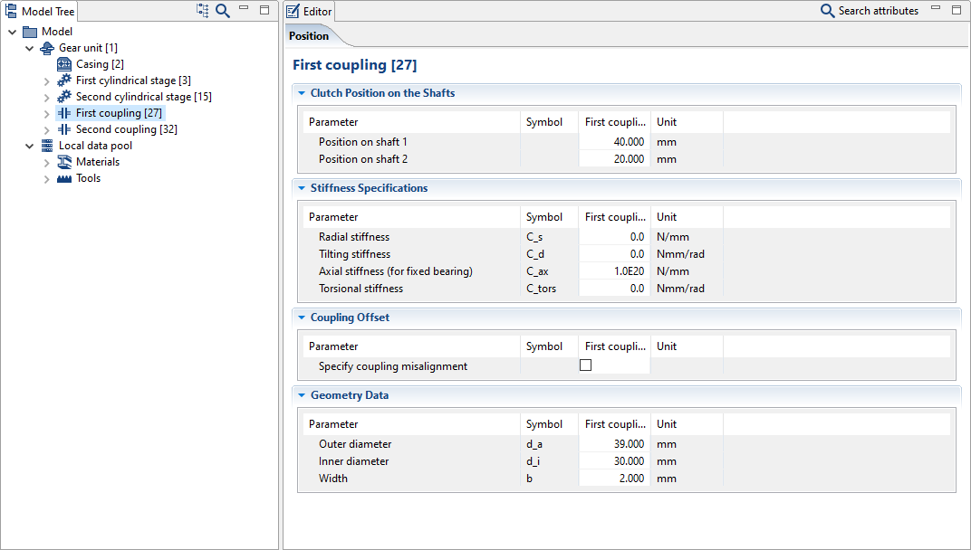
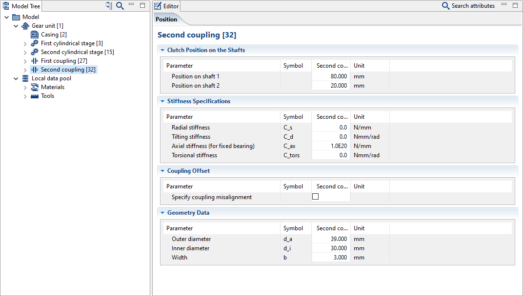
Specify the coupling data
Enter the coupling data as shown below.
Notice
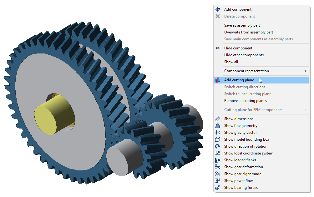
Right-click on a cylindrical gear in the 3D Model and choose "add cutting plane" to simplify the positioning of bearings and couplings.
Defining the power flow
Add load components
Right-click on the "input shaft" and "output shaft" in the Model Tree and add a load component for each. Enter 0mm as the position for both loads.
Rename the loads to "input load" and "output load," according to the shaft on which they are located.
Define the switch matrix and specify the load data
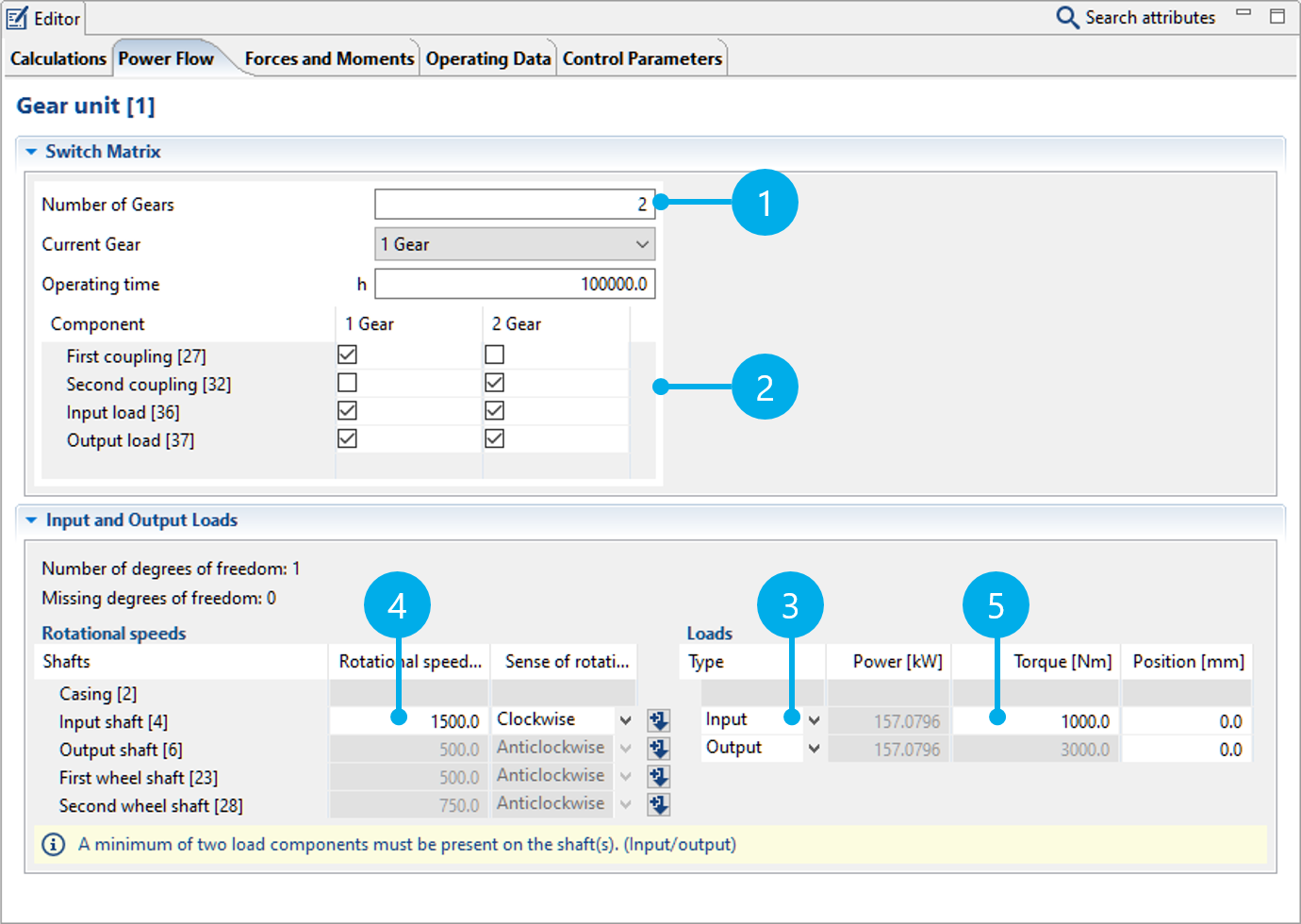
Select the gear unit in the Model Tree and go to the "power flow" tab.
Change the number of gears (1) to 2.
The switch matrix (2) defines which couplings or loads transmit power for each gear. Tick the boxes as shown in the image below.
Specify the load type (3).
Finally, enter the speed (4) and torque (5) for the "input shaft."
The power flow has now been sufficiently defined. The remaining speeds and torques will be calculated automatically.
Notice
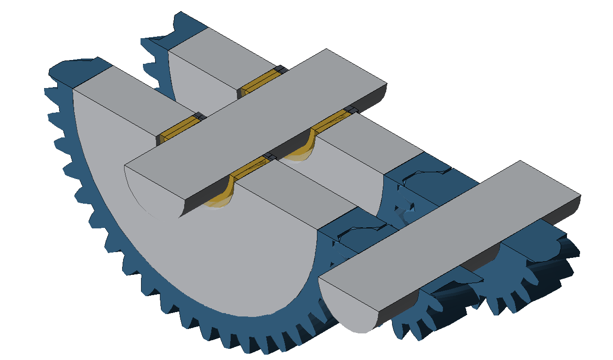
Right-click in the 3D View to activate the "show power flow" and "show loaded flanks" options. The 3D View will be updated when a different gear is selected in the power flow editor.