2D Modeler
The 2D Modeler projects the existing gearbox model onto a plane, which simplifies the modification of geometries, positions, and other properties. This is particularly beneficial for shaft modeling. As with drawing software, the shaft contour can be edited as a polyline in which individual or multiple points can be modified simultaneously. Edges can also be moved to the desired position using drag & drop. Snap functionality can be used with all drag & drop operations to automatically align to a grid or other components
Toolbar features

(1) | Current zoom factor |
(2) | Adjusts the displayed model size to the screen. |
(3) | Rotate the model by a specific angle. In the drop-down, you can select all angles in the model and their multiples. |
(4) | Rotates the currently selected shaft so that it is displayed horizontally. |
(5) | Snap to edges allows components to be automatically aligned with the edges of other components. |
(6) | Snap to grid enables the automatic alignment of objects to a grid. The grid size can be adjusted. |
Display options
2D Gearbox projection
This slider can be used to specify whether the gearbox is displayed in a wide or compact form. In the wide display, the gearbox components are arranged without overlapping as far as possible. However, depending on the gearbox configuration, some components may overlap. If necessary, individual components can be hidden using the checkboxes in the model tree.
Shaft details
The "Shaft details" checkbox can be used to show or hide the shaft centerline and the visible edges of the individual shaft sections.
Component icons
The “Component icons” checkbox can be used to show or hide the symbolic representation of components on the shaft, such as loads and notches.
Component properties
The modifiable properties of each component are displayed here.
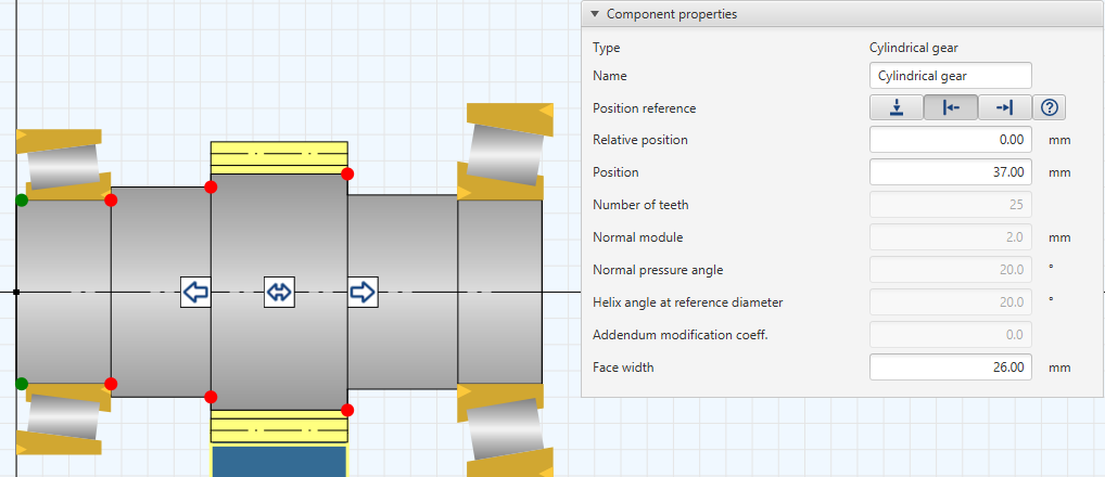
The “Position reference” property can be specified for each component. This is used to specify whether the relative position of a component should refer to the left  or rights
  side of the shaft section. If the shaft contour is modified, the component remains in its relative position. If
  is selected, the position of the component refers to the initial coordinate of the shaft.
Edit shaft contour
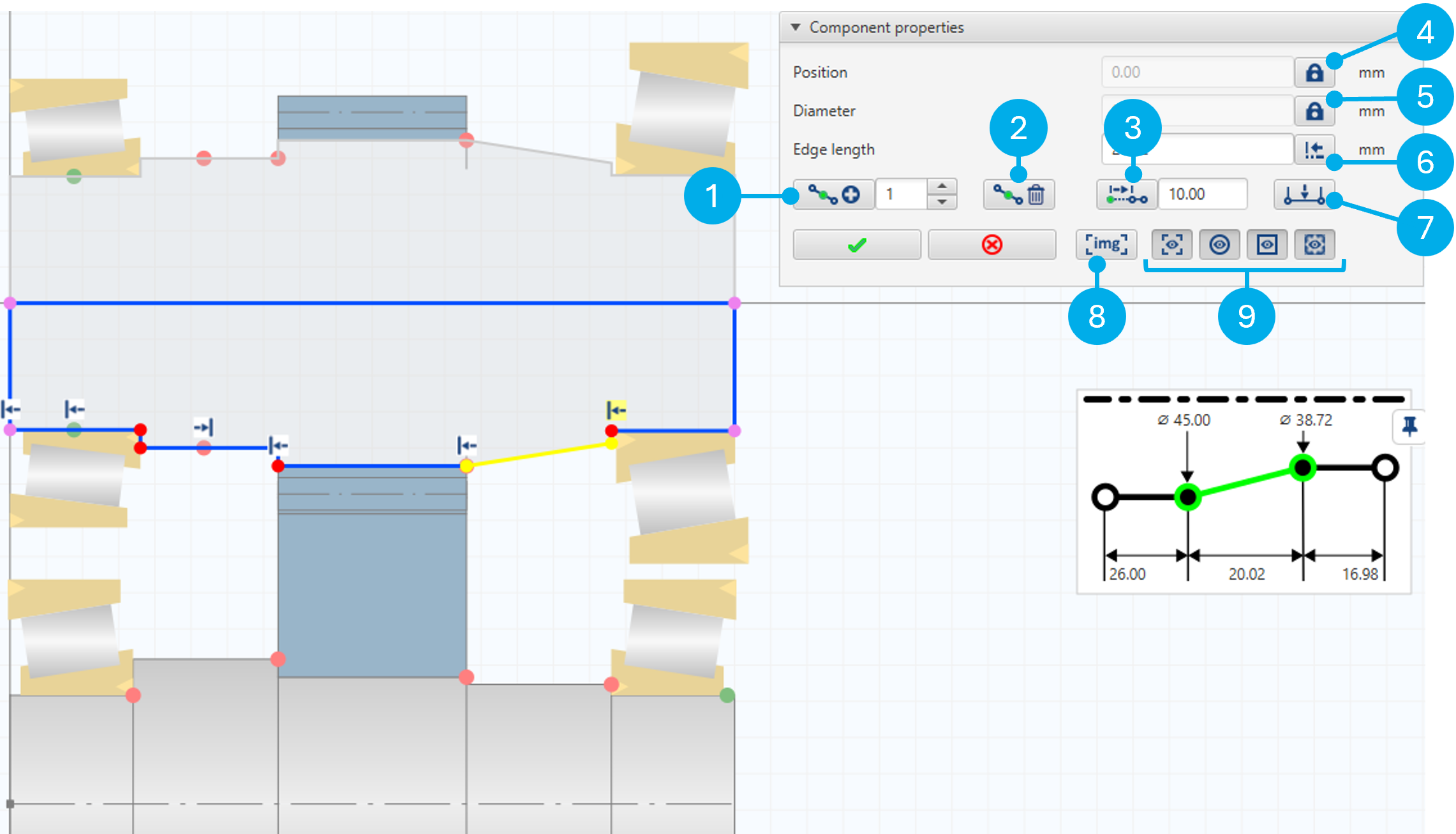
(1) | Insert new nodes on the selected edge. | Insert |
(2) | Delete one or more nodes. | Del |
(3) | Moves all nodes that follow the selected node to the right by the amount entered. | |
(4) | Locks the position input. | |
(5) | Locks the diameter input. | |
(6) | Lengthens or shortens the selected edge.
| |
(7) | Extrude the selected edge. | CTRL+E |
(8) | Opens the wizard for adding a background image for the shaft. |


Add background image to a shaft
To be able to easily recreate a shaft contour, it is possible to add a drawing as a background image.
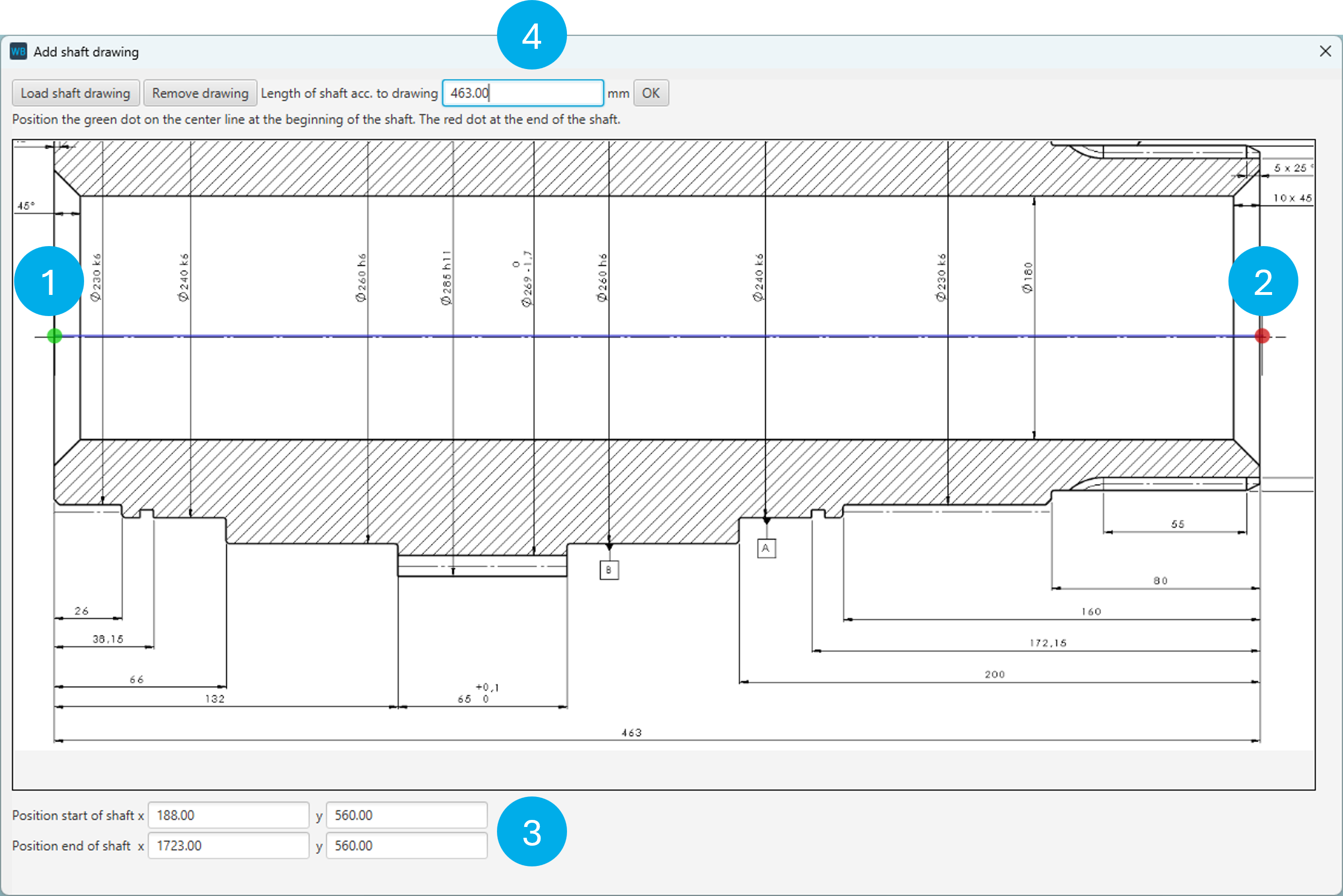
Once the image file has been loaded, the green point (1) must be placed at the start of the shaft and the red point (2) at the end of the shaft on the center line. The same applies if the shaft is displayed vertically or at a different angle. The X/Y coordinates of the points can be adjusted for exact positioning (3). In the last step, the length of the shaft must be specified according to the drawing (4).