FEM Gearbox Casings
The following tutorial demonstrates the process for importing and positioning FEM gearbox casings using an example single-stage industrial gearbox. It also covers determining the stiffness matrix as well as calculating and displaying the resulting component deformation.
The following files are needed to follow along with this tutorial in the FVA-Workbench:
Import and positioning
Load the fem_housing.wbpz gearbox model:
Project -> Open
Load the fem _housing.z88i1 casing mesh file:
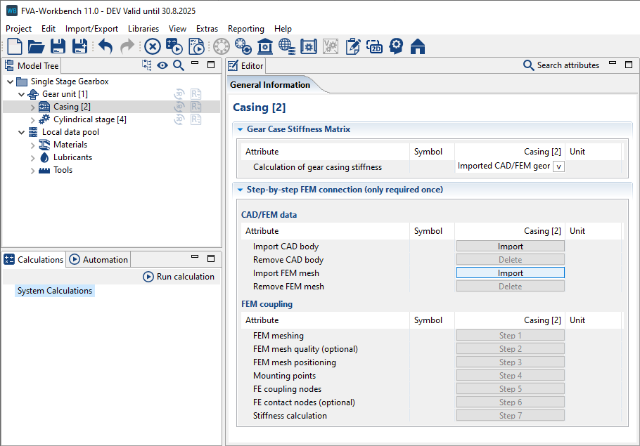
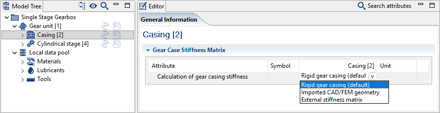
Select the casing component in the Model Tree and choose "Imported CAD/FEM Geometry" from the "Calculation of gear casing stiffness" drop-down menu in the Editor. Then, click Import next to "Import FEM mesh" to load the casing mesh file.
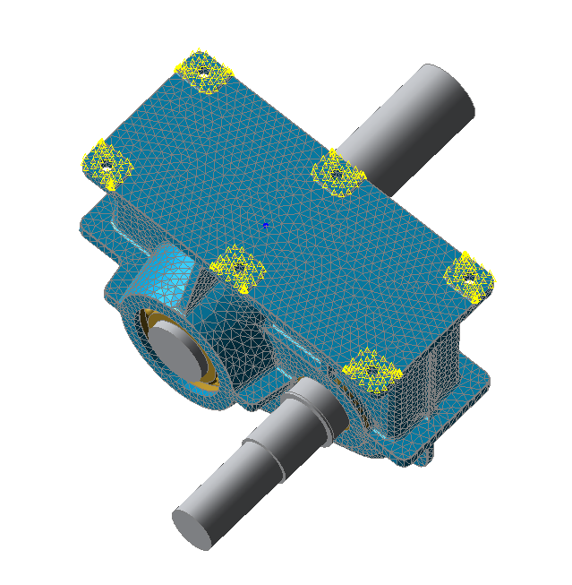
Confirm mm as the unit for the FEM model. The casing will initially be positioned in space independent of the gearbox model.
Choose a material for the new FEM subcomponent
Select the new FEM subcomponent under the Casing in the Model Tree. In the Editor, choose a material for the component from the drop-down menu. Once the material has been selected, switch back to the Casing component to continue the coupling process
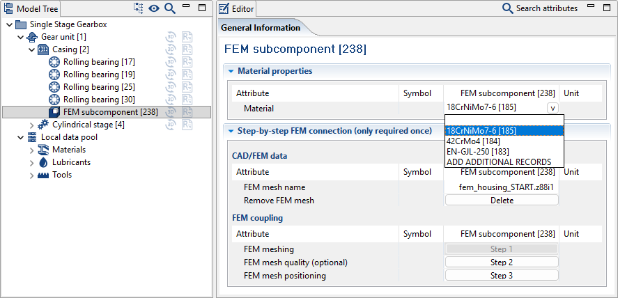
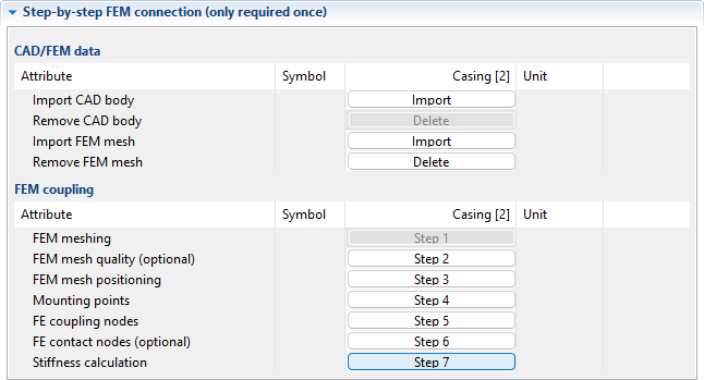
The steps for connecting the FE model to the gearbox structure are numbered and occur in order. Step 1 is not required for this tutorial (because of the imported FEM mesh), and Step 2 is optional.
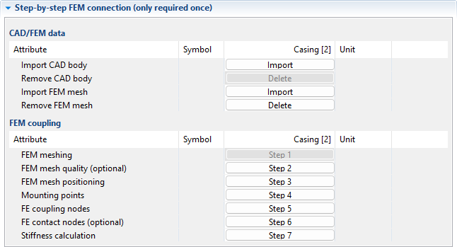
The assistant will guide you through the following steps in succession:
1. Position the casing
2. Determine the foundation nodes
3. Determine the bearing contact surfaces
4. Determine the contact nodes (for multi-part casings)
Step 3 FEM mesh positioning
5.1. Align the axis of the casing to the first shaft
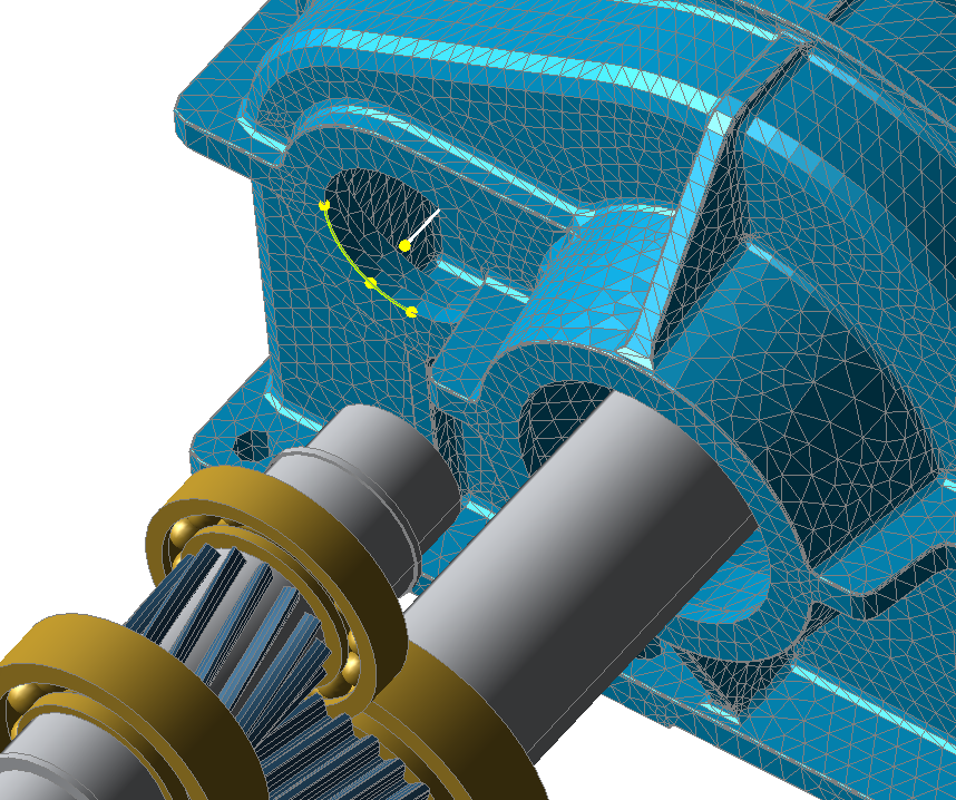
To do so, click Step 3, choose the "Shaft-based" working mode, select the reference shaft (Shaft [7]), and then select three node points on one of the two bearing seats.
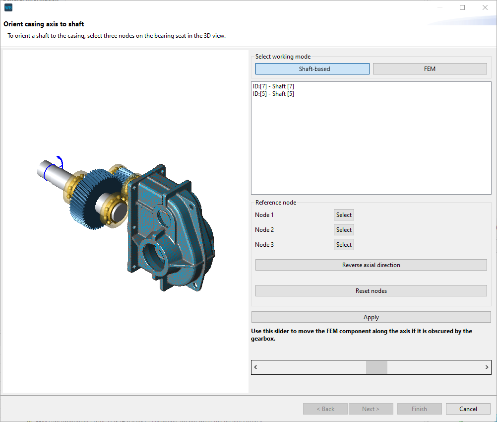
For orientation: The bearing seats with the larger diameter are for Shaft [7].
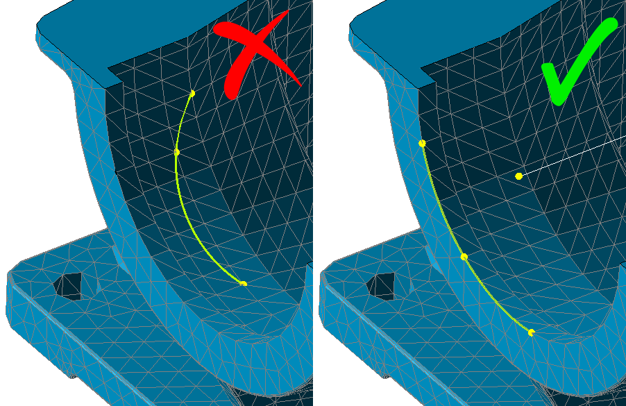
Notice
Select points along the edge of the bearing seat. The 3 nodes must span a plane whose midpoint corresponds to the midpoint of the shaft axis.
If the gearbox is mounted the wrong way around in the casing, click Reverse axial direction.
If the gearbox obscures the casing, use the slider to vary the distance between the gear unit and the casing. This feature is only to provide a better overview, it has no influence on the positioning.
Click "Apply" to align the reference shaft. The reference shaft can also be changed after the node points have been determined. The other shaft will then automatically be centered on the casing axis. Click "next" to complete the positioning of the first shaft.
5.2. Orient the axis of the casing to the second shaft
The reference shaft which has already been positioned is excluded from the list of shafts for positioning. Select the other shaft, choose 3 additional nodes on the bearing seats of Shaft [5], then click "Apply" and "Next" to complete the positioning of the second reference shaft.
5.3. Axial positioning of the casing
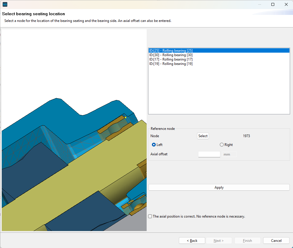
The next step determines the axial positioning of the shafts in the casing. To do so, use the contact surface of the bearing as a reference point.
Notice
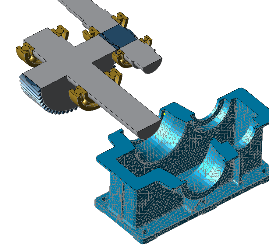
To provide better visibility of the contact surface, right-click on a shaft to create a cutting plane through the casing.
Select one of the individual nodes on the contact surface of the bearing. Use the "left" and "right" radio buttons to specify whether it is the left or right contact surface. Click "Apply" then "Finish" to complete Step 3.
Step 4 Define nodes to specify the boundaries
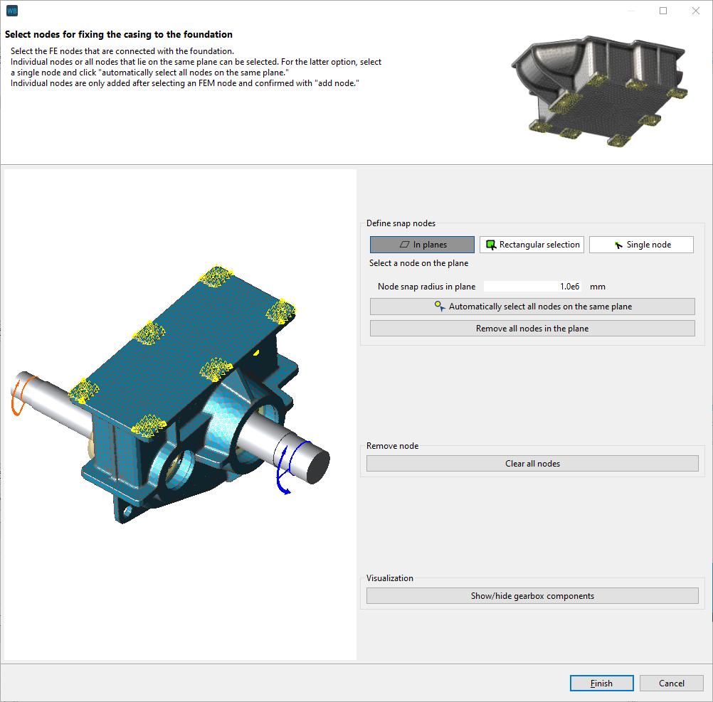
To define the connection of the casing to the foundation, individual nodes can be selected by hand, or all nodes in a plane or within an area selected with the mouse can be captured automatically.
In this example, the contact surfaces with the casing bores for bolting to the foundation are slightly raised. Therefore, all the node points are on a single plane and can be selected automatically.
Click the button for Step 4 and choose “In planes.” Select a node on one of the contact surfaces with a bore, then click "Automatically select all nodes on the same plane" to highlight all the nodes.
Click "Finish" to complete the step.
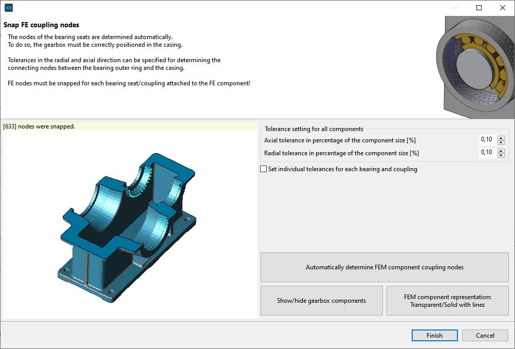
Step 5 FE coupling nodes
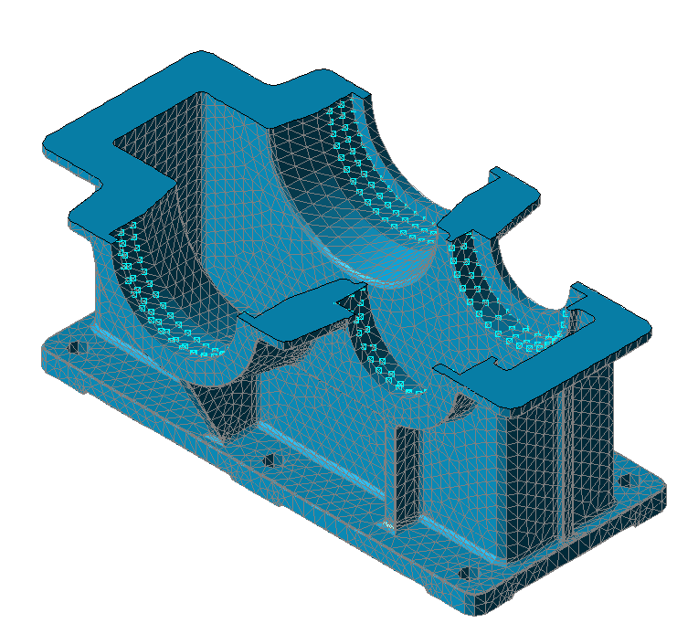
Click Step 5, then choose "Automatically determine FEM component coupling nodes." If the positioning is correct, all nodes that have a connection between the bearing seat and the bearing will be shown. Click "Finish." If no points are shown, or only a few, correction is required.
Notice
Any inaccuracies in the mesh can be compensated for by adjusting the tolerance in the radial and axial directions. The greater the selected tolerance, the more nodes that are snapped.
If the gear unit is tilted in the casing, repositioning is required.
The gear unit can be hidden and/or the casing can be made transparent to check the snapped bearing nodes.
Step 7 Calculate casing stiffness
Click the button for "stiffness calculation." After a successful calculation, the resulting stiffness matrix is considered in the system calculation.
Notice
The reduced stiffness matrix is saved in the gearbox model (.wbpz); it does not need to be determined every time the model is opened.
The "Calculation of casing stiffness" drop-down menu determines whether the stiffness matrix for the FE component is considered in the system calculation.
The calculated stiffness matrix for an FEM component is automatically considered in the system calculation. If “Rigid gear casing” is selected, the FE casing is not considered in the stiffness calculation. If “External stiffness matrix” is selected, an externally calculated stiffness matrix can be considered in the system calculation.
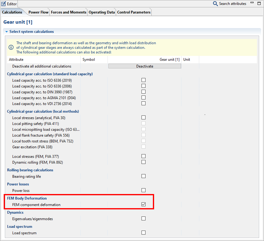
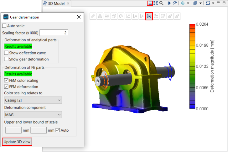
Calculating component deformation
To visualize the deformation of the casing in the 3D Model view, select the Gear Unit in the Model Tree, enable the "FEM component deformation" calculation in the Editor, and run a system calculation. To view the FEM component deformation, enable the 3D Toolbar in the 3D Model view and click the button for “Gear deformation.” Choose your options in the pop-up window, and then click the “Update 3D view” button.