User interface
The FVA-Workbench user interface consists of multiple windows, so-called views. The size and position of these views can be adjusted.
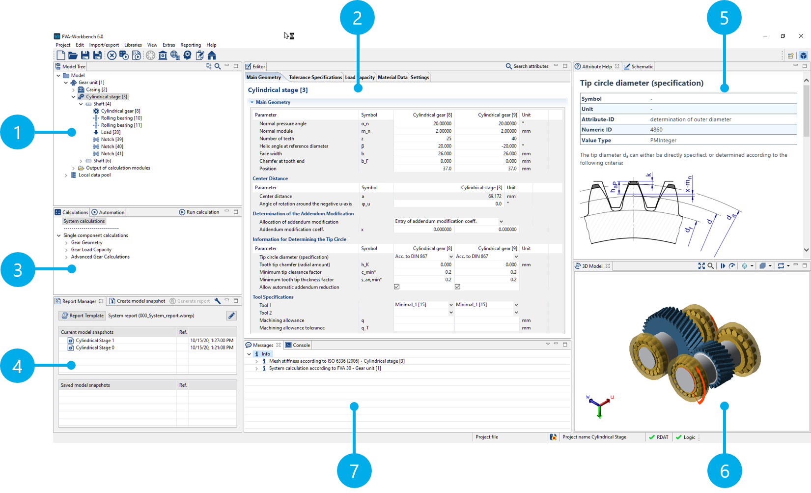
(1) Model Tree
(2) Editor
(3) Calculations
(4) Report Manager
(5) Attribute Help
(6) 3D Model
(7) Messages
Model Tree
The "Model Tree" view represents the gear unit in a hierarchical tree structure. The components (machine elements) are arranged according to their actual arrangement in the gearbox. Depending on the component type, different actions can be performed by right-clicking on the component, such as adding and removing machine elements, adding components from the Assembly Part Library, or overwriting existing components.
Editor
Every component in the gearbox model has a set of attributes (parameters), which are displayed in the "Editor" view. These attributes are grouped thematically into tabs. Tabs and attributes are hidden or shown, depending on the selected system or individual component calculations.
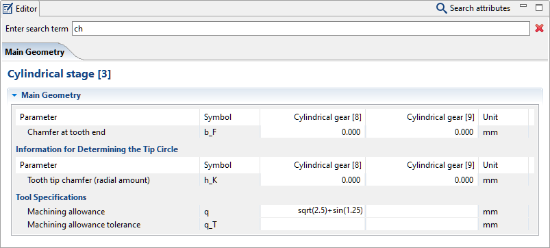
CTRL + F activates the search function in the Editor. Only attributes that are valid for the currently selected component will be found.
Calculation operations can be carried out in input fields for numeric values. In addition to basic arithmetic operations, the following functions are available: sin cos abs int deg rad sqrt
Calculations
Different calculations are available here, depending on the component selected in the Model Tree. Double-clicking on one of these calculations starts a single component calculation.
The system calculation is always shown, regardless of the selected component. For more information, see System calculation.
Report Manager
Following a calculation, a Model Snapshot is created in the Report Manager. The Model Snapshot contains all inputs and outputs from the time of the calculation. The data in the Model Snapshot can be visualized in a results report. Templates can be used to manage the information included in the report. For more information, see Report Manager.
Attribute Help
Attribute Help is available for many input attributes in the FVA-Workbench, which provides more detailed information about the parameter.
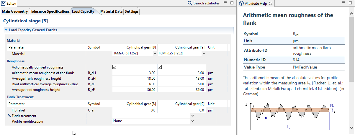
F1 opens the Attribute Help. Click on the attribute name to view the help text for the attribute.
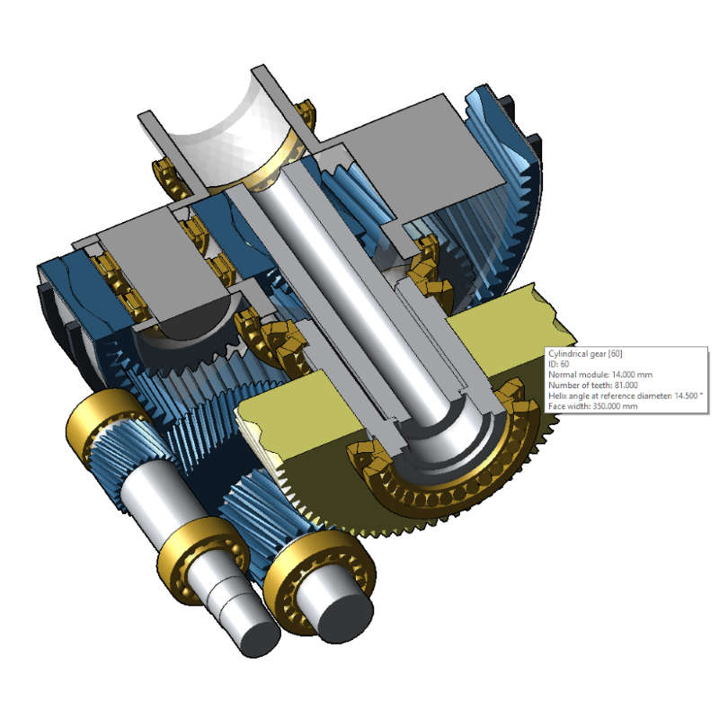
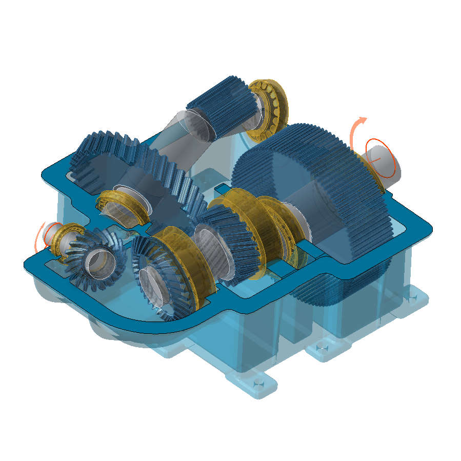
3D Model
This view shows an accurate and detailed 3D representation of the gearbox model. Cutting planes can be used to provide an overview of complex gearboxes and detect possible input errors. Calculation results, such as bearing deformation, eigenmodes, or the power flow, can also be displayed directly in the 3D Model. As with the Model Tree, gearbox components can be added and removed directly in the 3D View.
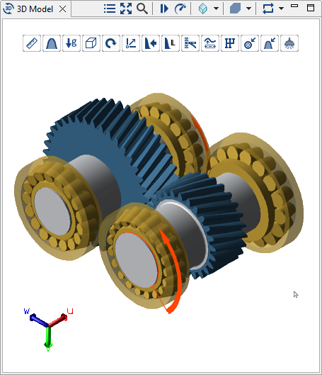
A variety of display options are available from the 3D Toolbar.
Cutting planes
Cutting planes provide better insight into the gearbox structure and simplify operation, especially when positioning components and modeling shafts. Cutting planes can be applied globally through the entire gear unit or locally through a single component.
Right-click on a component in the 3D View to apply cutting planes. Right-click on a component a second time to switch to a local cutting plane.
Gear deformation
The deformation of the shaft-bearing-gear system is always considered in the system calculation. An adjustable scaling factor can be used to view the deformation in the 3D View. If FE components (e.g., casing or planet carrier) are included in the gear model, an additional "calculate FEM component deformation" step can be activated for the system calculation. This determines the resulting deformation for all nodes of the FE meshes. This can be used to identify trends and simplify the interpretation of results.
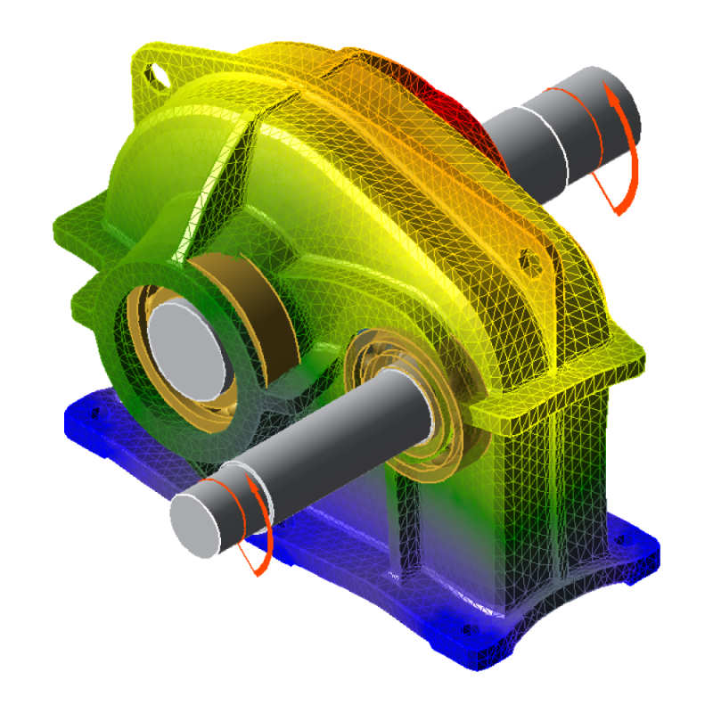
Right-click in the 3D View and choose "show gear deformation" to display the deformation resulting from the system calculation. If "calculate FEM component deformation" is activated, the deformation of FE components can also be displayed.
Detailed geometry
The cylindrical and bevel gear geometry calculations provide a detailed description of the tooth and flank forms. Once the calculation has been performed, you can toggle between simplified and detailed representation of the geometry in the 3D View.

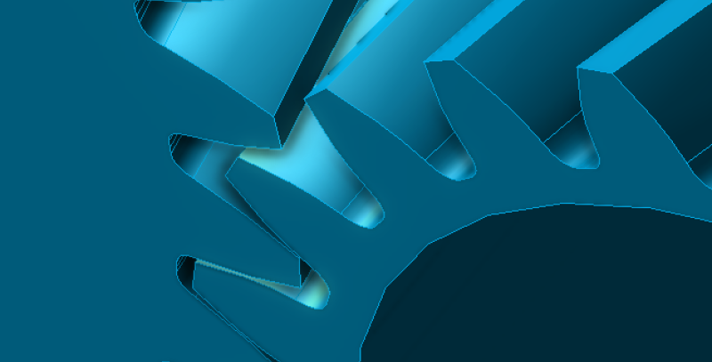
Right-click in the 3D View and select "show fine geometry" to switch between the simplified (left) and detailed geometry (right).
Eigenmodes
The gearbox eigenmodes can be calculated as part of the system calculation.
Once the gearbox eigenmodes have been calculated, they can be animated and exported by right-clicking in the 3D View and selecting "show gear eigenmodes."
Messages
Information about the current calculation is shown in the Messages view. Messages include information, warnings, or errors. Messages will also be output if required calculation parameters are missing or outside the value range.
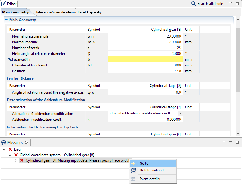
Right-click on an error message to jump to the appropriate location in the Editor.
Global Database
Various types of records (e.g., lubricant or tool data) can be saved in the Global Database, without referencing a specific gear unit model.
To be able to use records from the Global Database, they must be added to a gear model as a new component. This creates a copy of the record in the so-called local database which can be edited by the user. However, a reference to the record from the Global Database is maintained, so that the original data can be restored by right-clicking on the database component.
The records are saved in .dat files. Separate storage locations can be specified for each type of record under Settings -> Databases. By default, the database files are stored in the database subfolder of the FVA-Workbench installation directory.
Once they have been created, records can be used in different models and by different users.
The following records can be saved in the Global Database:
Lubricants
Materials
Gear cutting tools
Load spectra
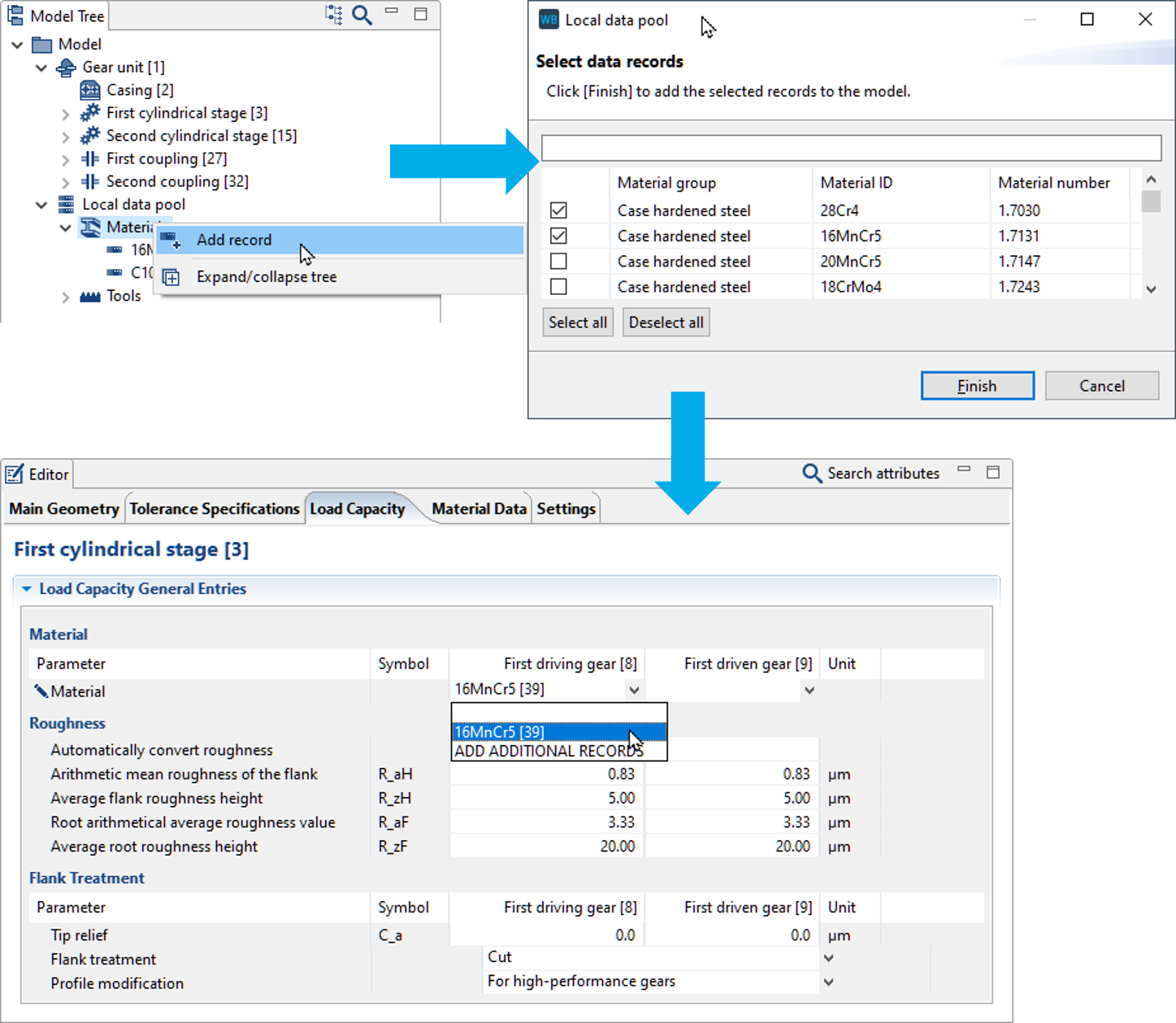
In this example, a new material record is added by right-clicking on the Model Tree. Multiple materials can be selected in the selection dialog. The selected materials are then shown as components in the Model Tree. The added materials can now be selected in the Editor, for example as a material for cylindrical gears.
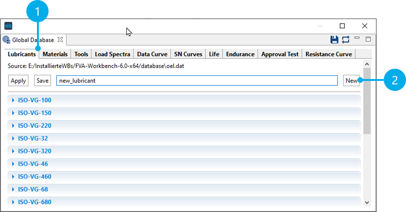
Click the  symbol in the Toolbar to open the Global Database. Separate tabs (1) are available for each record in which all entries are listed.
To create a new entry, a name must be specified. Click New (2) to create a new record.
Assembly Part Library
Frequently used components or entire assemblies can be saved in the Assembly Part Library and reused in other FVA-Workbench models.
Notice
The location of the elements can be specified under Extras -> Settings-> Assembly Parts.
Saving assembly parts
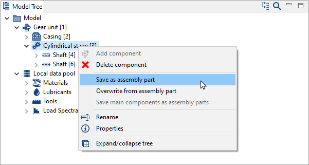
Right-click on a component in the Model Tree to save it and its sub-components as an assembly part.
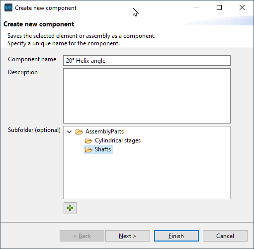
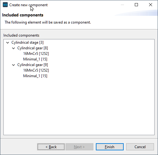
Assembly parts can be organized in subfolders. The last step of the wizard shows which sub-components are saved in the assembly part.
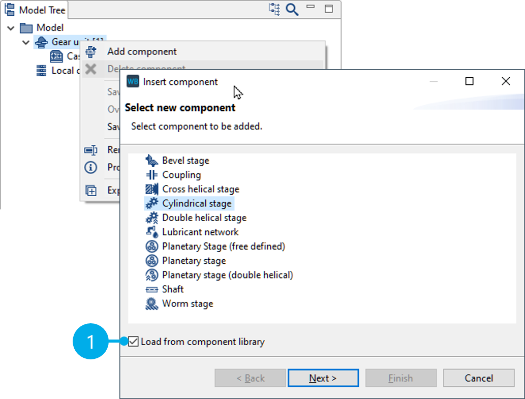
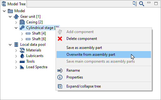
Adding assembly parts
Assembly parts can be selected when a new component is added (left, 1), or existing components can be overwritten (right).
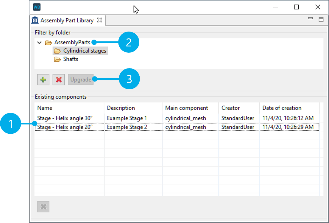
Assembly Part Library
The "Assembly Part Library" view  shows an overview (1) of the saved assembly parts. Right-click on an assembly part to rename it, enter a description, or create a new folder.
Notice
Assembly parts that were created in a version of the FVA-Workbench older than 5.5 must be updated. To do this, select the root directory (1) and then click "Upgrade" (3).
All saved assembly parts are shown in the "Assembly Part Library" view.