FVA-Workbench 9.2.0
Features
Variant comparisons can be used to compare attributes from multiple model snapshots. Tables and diagrams are available for evaluating the data.
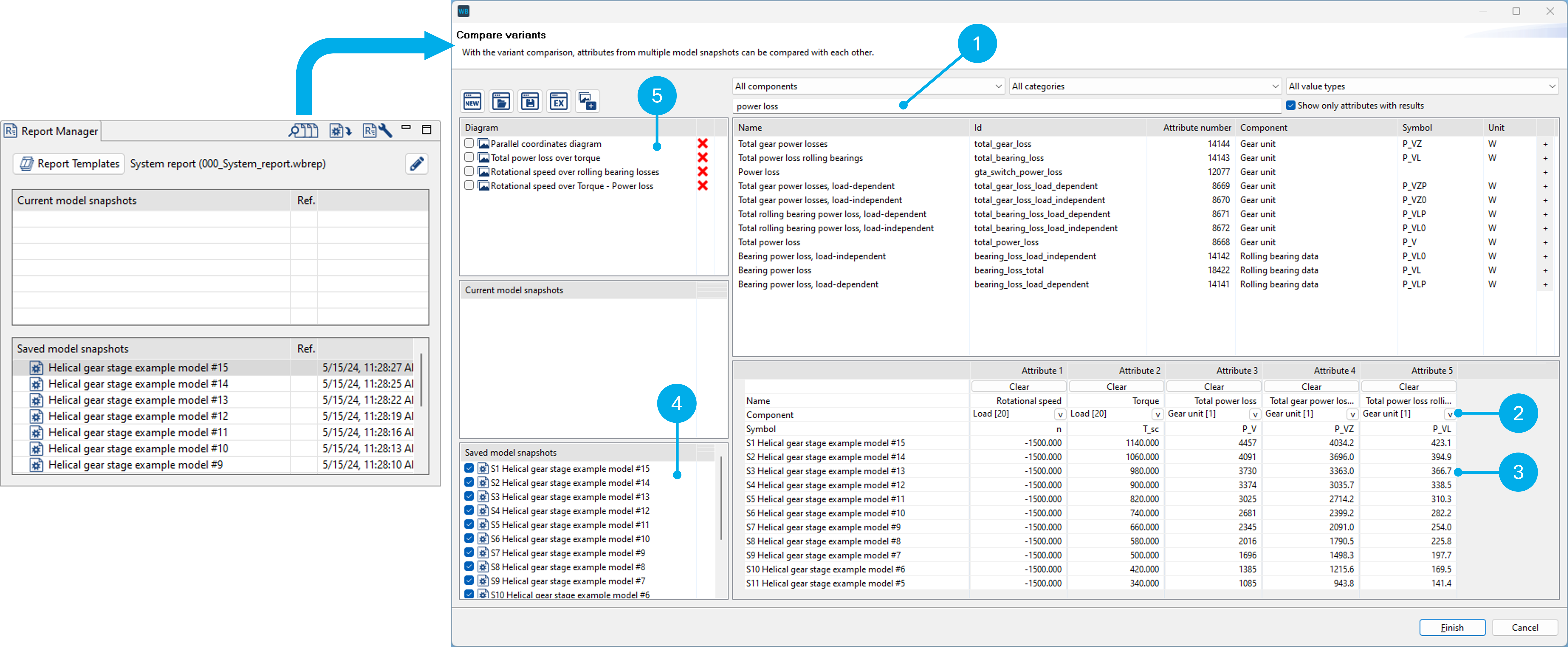
To perform a comparison, select the attributes to be compared (1) and a component (2). The values for these attribute-component combinations are displayed in columns (3) for each selected model snapshot (4). In addition to tables, diagrams (5) are also available for comparing the attribute values. The selected attributes, components, and diagrams can be saved as templates. To use the templates for a different gearbox model, only the components need to be reselected.
Figure 41. Parallel coordinate diagram 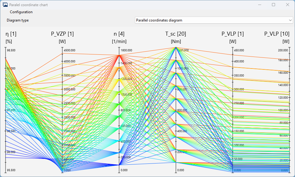 For this type of diagram, all selected scalar attributes are each displayed on their own axis. | Figure 42. XY diagram 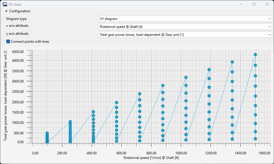 For XY diagrams, a scalar attribute must be specified for each axis. |
Figure 43. Bubble diagram 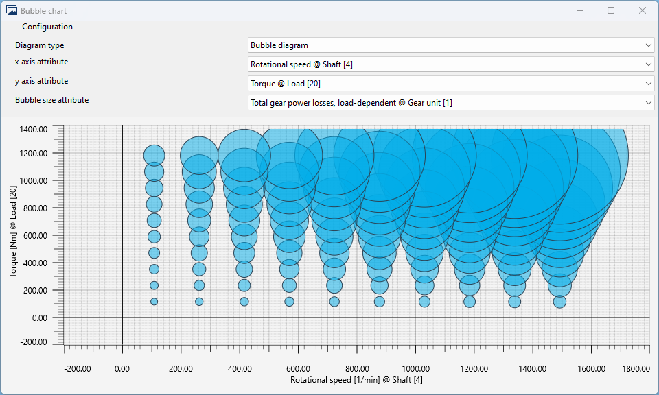 For bubble diagrams, a scalar attribute must be specified for each axis. Another scalar attribute determines the size of the bubble. | Figure 44. Curve array 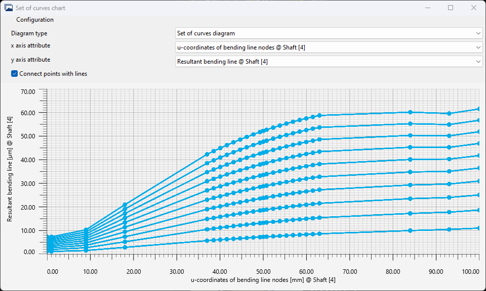 The curve array diagram can be used to display array attributes. |
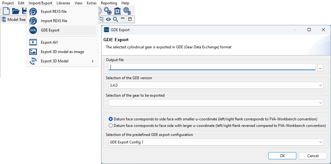
The new GDE export function makes it possible to export the geometry data of a cylindrical gear, including flank changes and tolerances, in GDE format. Up to 4 different export configurations can be defined in the FVA-Workbench settings. One of these export configurations can then simply be selected in the export dialog. The GDE export can also be fully automated using the scripting functionality in the FVA-Workbench.
For more information see GDE Interface
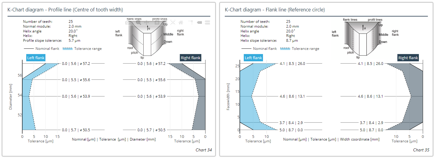
In K-chart diagrams, the positions along the diameter or face width along with the associated tolerance values are now shown for all inflection points of the curve profiles.
The type of width modification can now be directly specified for LRS 2019. Specification of modification components is no longer considered.
The proposed tip relief according to SIGG is now also output without calculation of the local load distribution.
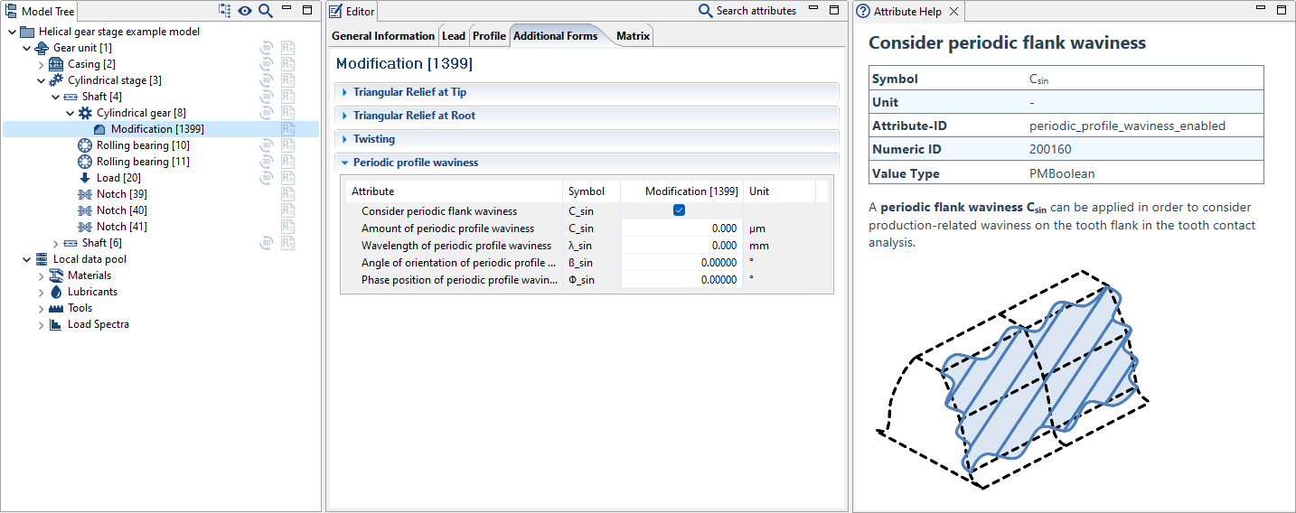
Flank waviness can now be selected as a type of modification.
The calculated 3D modification proposal can now be specified in the editor as a modification matrix.
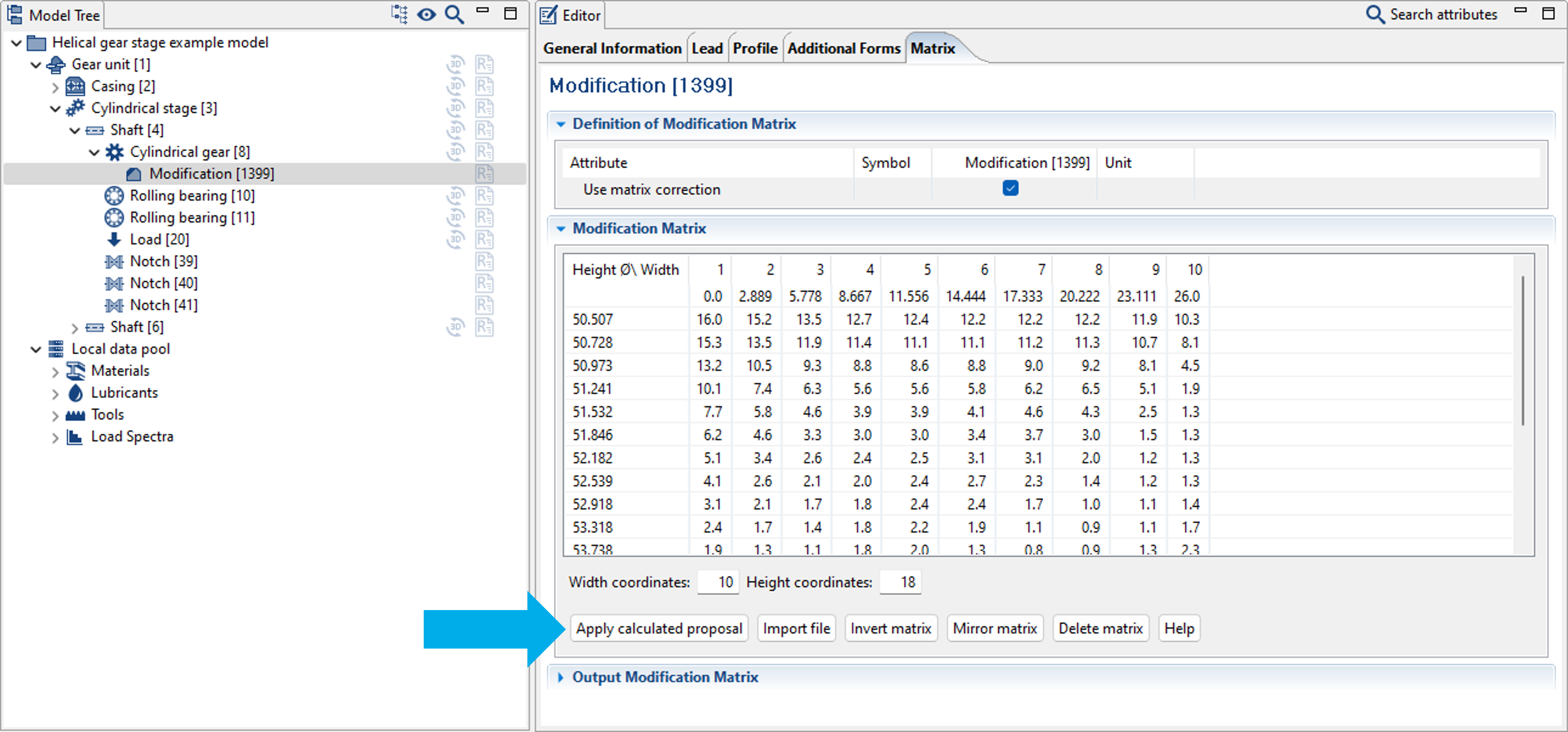
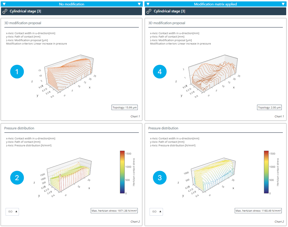
The proposed modification (1) is a result of the local stress calculation. This proposal can be used as a modification matrix in the Editor. Without modification, the pressure distribution is uneven with large stress peaks (2). After applying the modification matrix and recalculating, a uniform pressure distribution is obtained (3). The remaining residual modification is negligible (4).
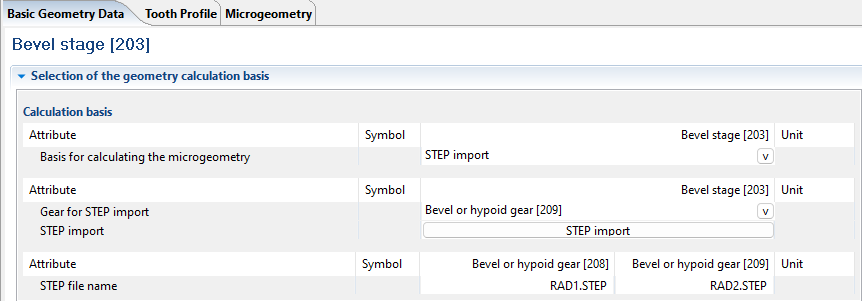
The new STEP import for the ISO 23509 calculation can be used to import the 3D tooth geometry as CAD geometry in STEP format. The calculation is then performed for the surfaces defined in the STEP file. This requires correct positioning of the gears and identification of the flank features.
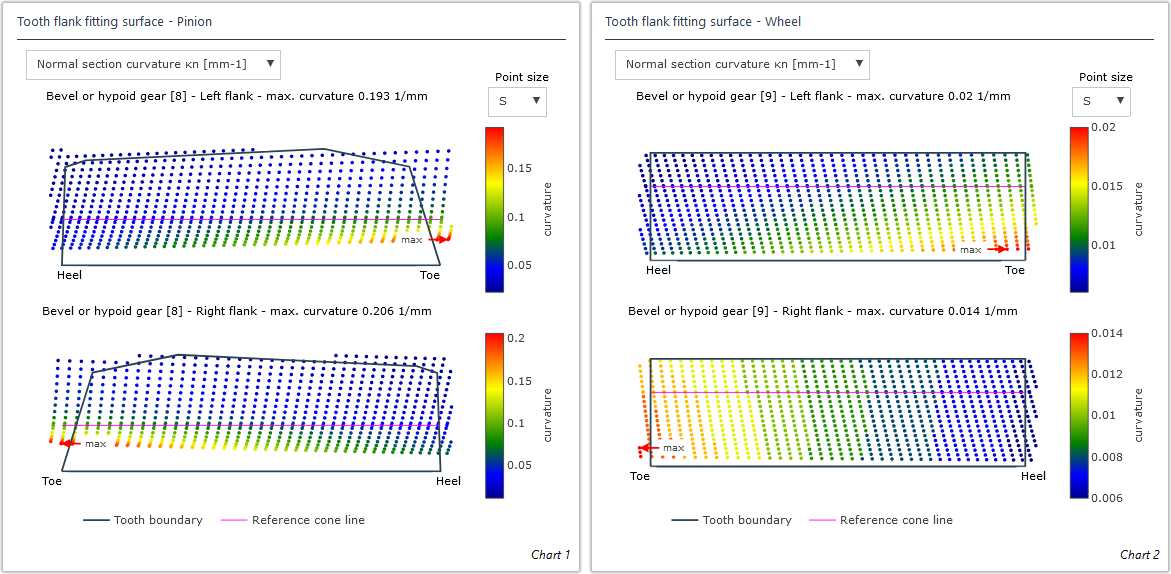
New diagrams for displaying the local curvatures of the fitting surfaces.
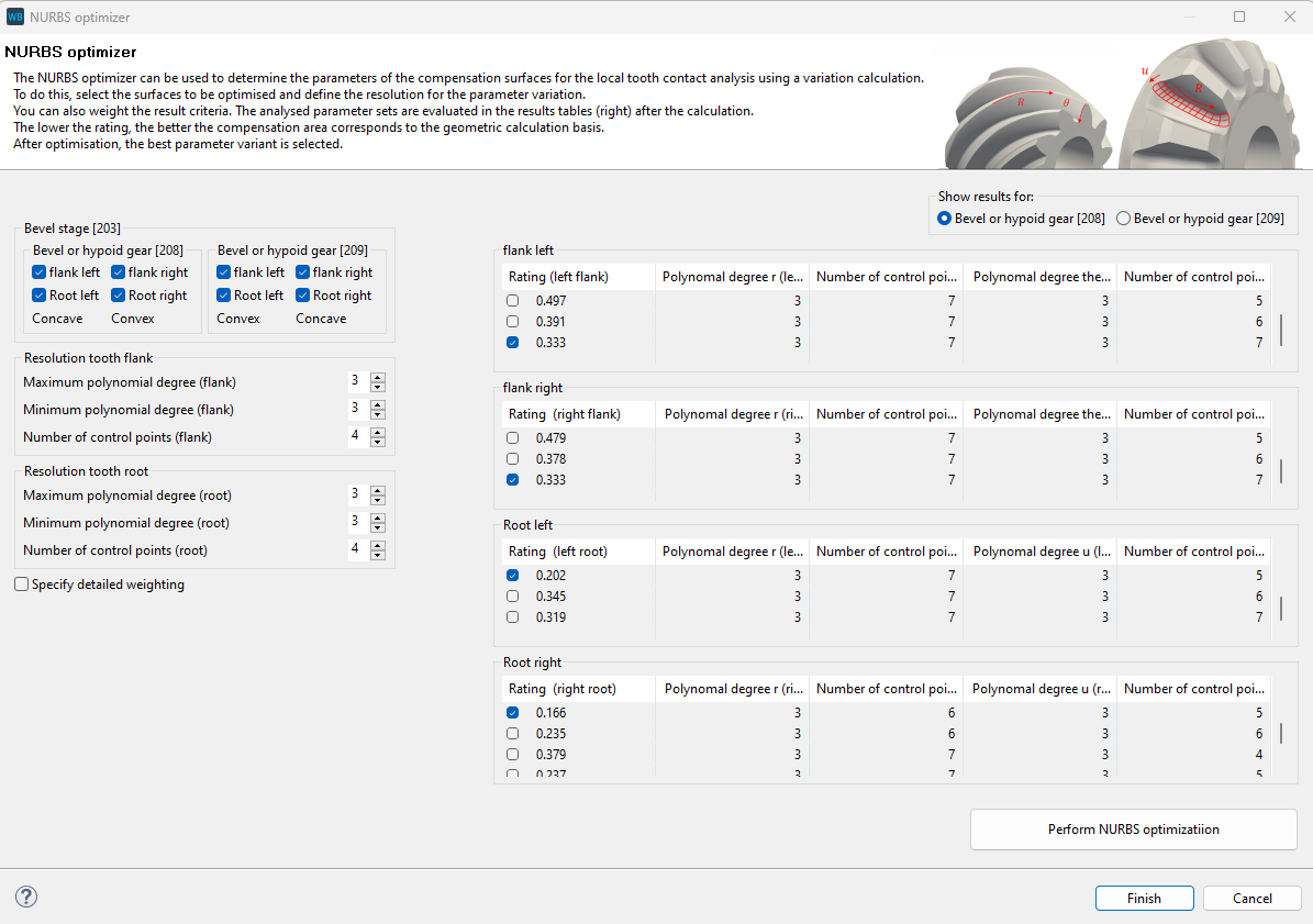
The new NURBS optimizer can be used to determine the parameters of the fitting surfaces for the local tooth contact analysis via a comparison calculation. The results criteria can be weighted. The lower the weighting, the more the fitting surface corresponds to the basis of the geometric calculation.
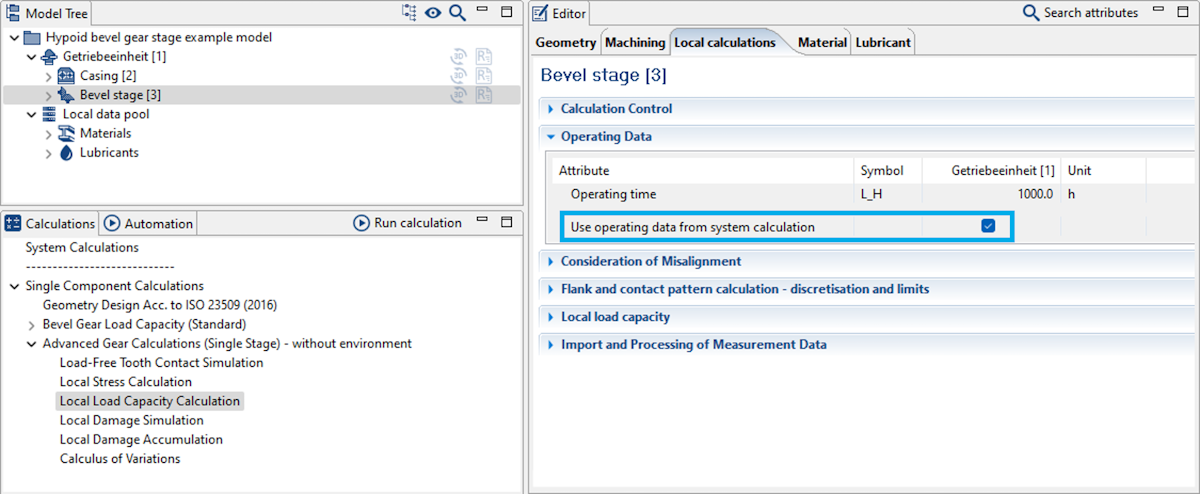
As with the standard calculation, the operating data can optionally be taken from the overall system for the individual "extended gear calculation."
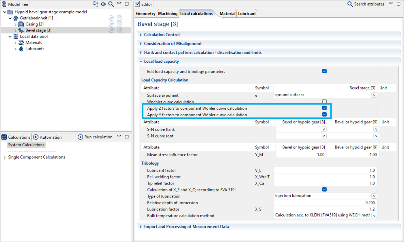
If calculation of the Woehler S-N curve is not activated, the S-N curve must be specified within the program via the corresponding database. Consideration of the Z-factors from FVA 411 for the pitting load capacity or the Y-factors from ISO 10300 for the root load capacity for the specified Woehler S-N curve can now also be activated. Similar to ISO 6336-5 2019 Annex B, Y_M can be used to specify a mean stress influence factor for the tooth root for bevel gears.
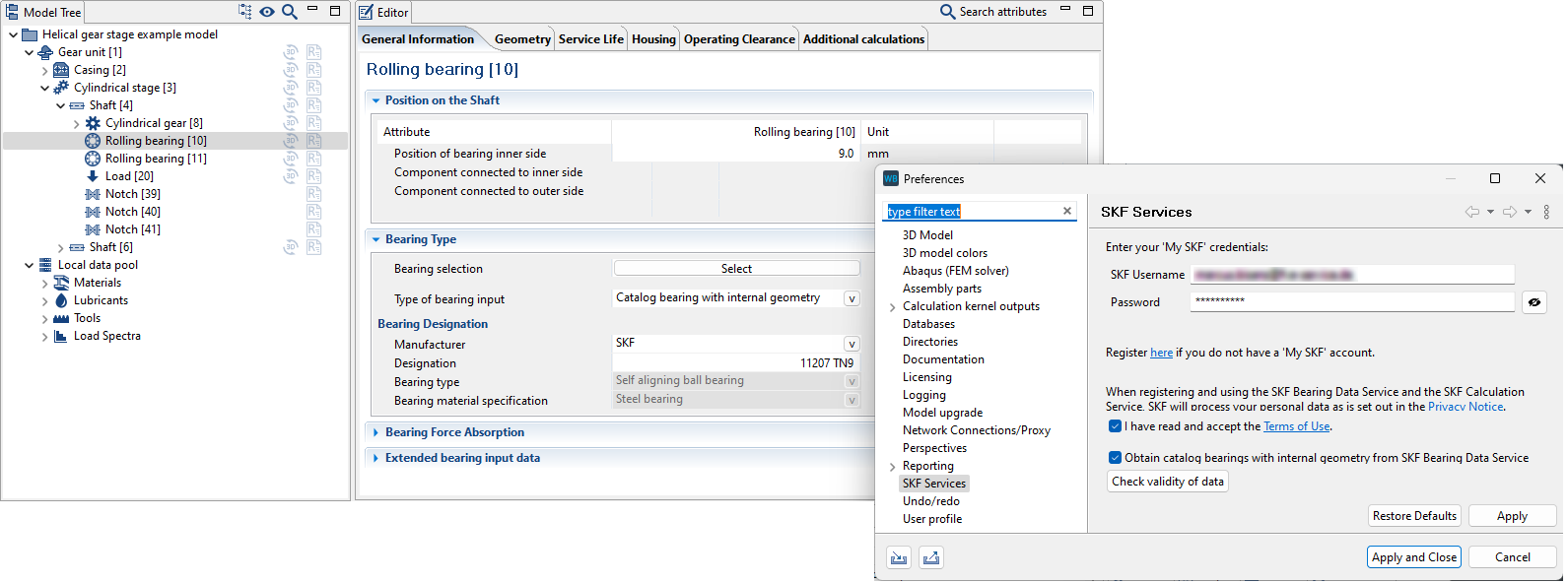
The SKF Bearing Data Service has now been integrated along with the SKF Calculation Service. If activated in the settings, the internal geometry can be obtained directly from SKF for all SKF bearings.
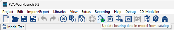
All catalog bearings in the model can now be updated from the current bearing catalog with a single click. If the SKF Bearing Data Service is activated, the internal geometry for SKF bearings is obtained directly from SKF.
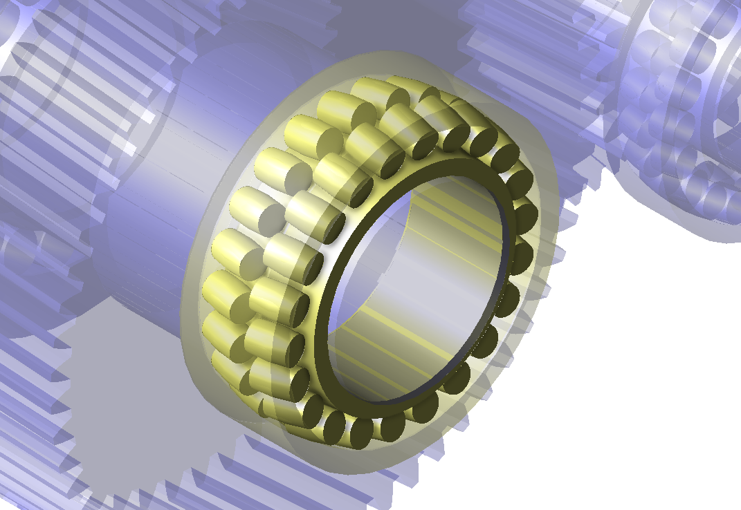
Representation of rolling bearings in the 3D Model has been improved and is now based on the specified or estimated bearing internal geometry.
Calculation of the reference service life according to ISO 16281 has been updated. In particular, this leads to the following changes:
- determination of the modified service life for double-row ball bearings
- the operating pressure angle of each roller is now considered in the determination of the bearing operating point for spherical roller bearings.
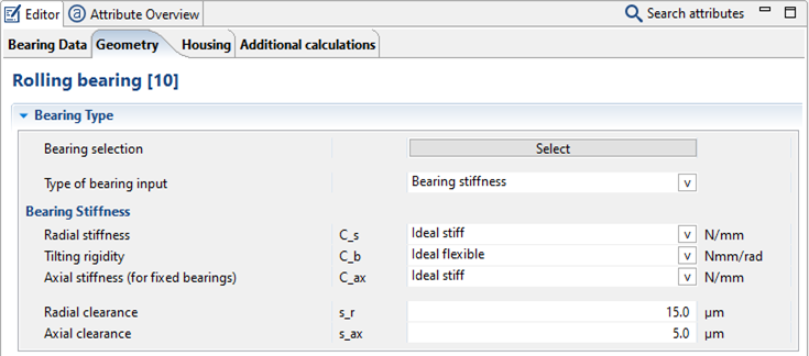
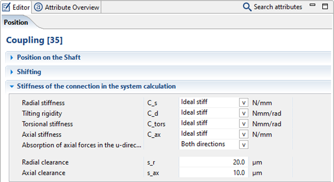
Axial and radial clearance can now be considered in the overall mechanical system for concept bearings, couplings, and shaft-hub connections.
An operating clearance can now also be specified or calculated for single-row angular contact ball bearings.
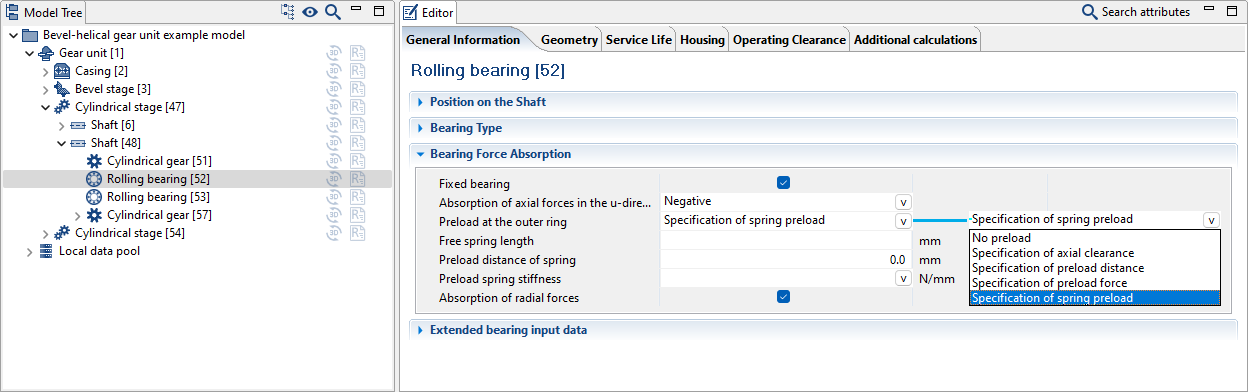
Axial springs on the outer ring can now be considered for single-sided axial mounting. The spring length and spring stiffness (linear or non-linear) can be freely defined. A preload path can also be defined for the spring.
If the internal geometry is known, hybrid bearings with ceramic rolling elements can now also be considered in the FVA-Workbench, and the basic rating life can be determined according to ISO 281 and ISO 16281.
Double row axial-cylindrical roller bearings can now be correctly considered.
The TIMKEN bearing catalog has been updated and expanded to include deep groove ball bearings.
The SKF bearing catalog has been updated.
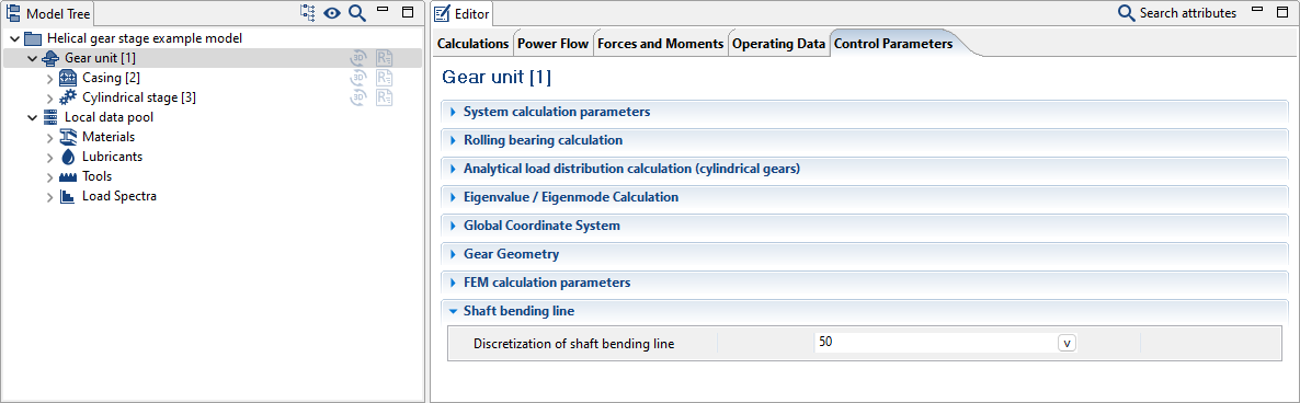
The number of nodes to be calculated for the bending lines can now be specified. The nodes are evenly distributed along the length of the shaft bending line.
The results are written to the following attributes:
u-coordinates of the node (bending_line_u_position_discretized)
Bending line in v-direction (bending_line_in_v_direction)
Bending line in w-direction (bending_line_in_w_direction)
Resulting bending line (bending_line_v_w_absolute)
A 3D mouse (Connexion) can now be used to control the view in the 3D Model.
The FVA-Workbench configuration files are now stored in the %appdata% folder of the user directory.
The JAVA runtime environment supplied with the FVA-Workbench has been updated to version 21.
Installation of the JAVA runtime environment can now be deselected in the FVA-Workbench installer.
Bugfixes
Bevel gears
The addendum and dedendum are now correctly calculated for standard calculations when importing machine settings data for bevel gears with angle modifications.
Representation of the amount and direction of the gear meshing forces for bevel gear stages in the 3D Model has been corrected.
Rolling bearings
The material for the side plate can now be accessed for calculation of the operating clearance of planetary bearings.
An error in the determination of the contamination coefficient of planetary bearings according to ISO 281 Annex A has been corrected.
Cylindrical gears
Adaptation of the evaluation of the deformation behavior of materials (brittle, ductile with/without pronounced yield strength) for ISO 6336 and DIN 6892.
Load spectra
An error in the calculation of load spectra for switchable gears with load-free gear stages has been corrected.
The mesh-dependent Woehler S-N curve according to ISO 6336 is now correctly displayed in the load spectrum.
FEM
An error with the import of multiple FEM meshes has been corrected.