Power Splitting
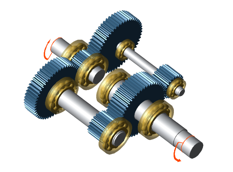
This tutorial demonstrates power splitting and the associated settings. Power splitting makes it possible to divide the power flow between multiple parallel shafts.
The following files are required to follow along with this tutorial in the FVA-Workbench:
Modeling
Load the power_split.wbpz gearbox model:
Project -> Open
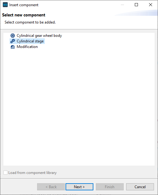
Add a cylindrical stage
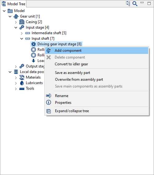
Right click "Driving gear input stage [8]" in the Model Tree and add a new cylindrical stage component.
Specify the gear data
Enter the gear and material data in the wizard as shown in the image below.
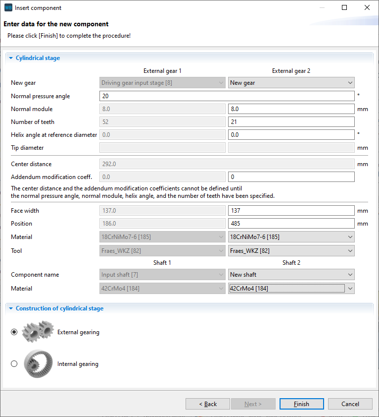
Select "new shaft" for Shaft 2. A new shaft and gear will be created. This shaft is not yet positioned and does not have any contours.
Right-click on the new shaft in the Model Tree and rename it to "parallel intermediate shaft."
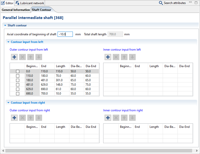
Adjust the shaft position and contour
Select "Parallel intermediate shaft [368]" in the Model Tree and switch to the Shaft Contour tab in the Editor. Now, add new shaft sections and change the diameters and lengths as shown in the image below. Enter -10 for the axial coordinate of the beginning of the shaft.
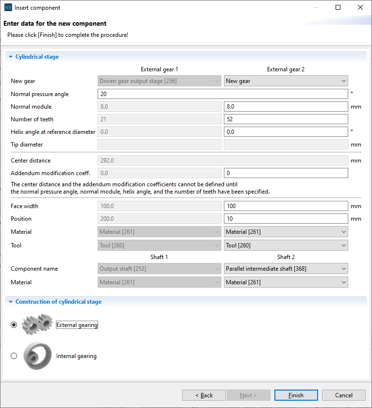
Add a cylindrical stage
Right-click "Driven gear output stage [256]" in the Model Tree, create a new cylindrical stage, and enter the gear data as shown in the image below.
Select "parallel intermediate shaft" as the shaft for the new gear.
Add rolling bearings
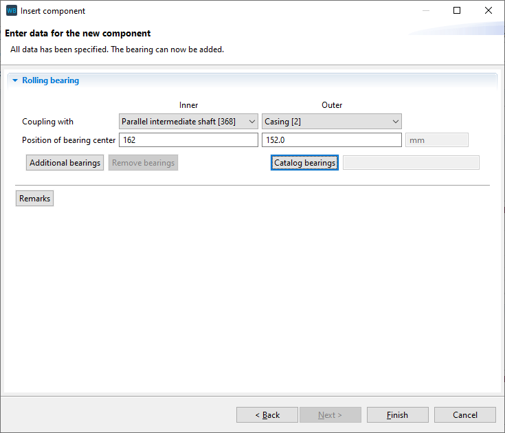
Right-click "Parallel intermediate shaft [368]" in the Model Tree and add a new rolling bearing component.
Couple the inner ring with "parallel intermediate shaft" and the outer ring with the casing. Specify 162mm for the position of the bearing center of the inner ring.
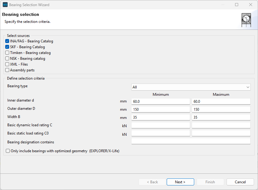
Now, click "catalog bearings" and enter the search criteria as shown below.
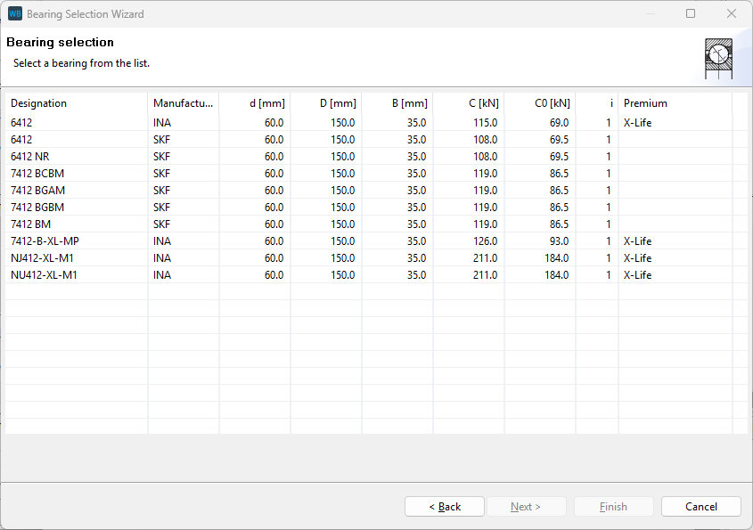
Select one of the 6412 bearings and click "Finish."
Add another rolling bearing
Repeat step 6 to add a second, identical bearing on the same shaft. Enter 645mm for the position of the inner ring of this bearing.
Define the power flow
Power splitting can be defined in two ways in the FVA-Workbench:
Power splitting depending on the gearbox stiffness | Uniform power distribution across the power paths |
This is the standard option which will automatically be used during the system calculation. By default, the resulting torques are considered in the system calculation. | This calculation must be specifically activated. Select the Gear Unit in the Model Tree, switch to the Control Parameters tab, and select the checkbox for "Consider nominal torques for calculation." The load is then transferred evenly across the stages |
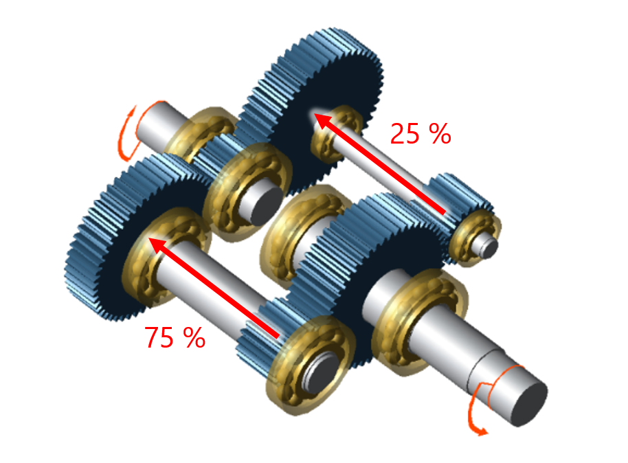 |  |
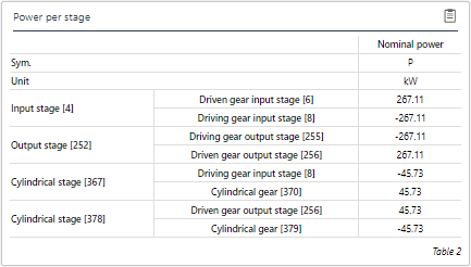 The power path with the stiffer, more rigid shaft transmits significantly more power | 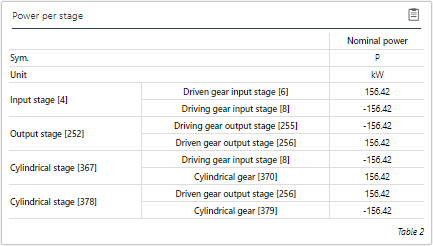 Each of the power paths transmits exactly 50% of the power |