FVA-Workbench 10.1.0
Features
Asymmetric gears can now be considered. The following calculations can be performed with these gears:
Geometry calculations based on the specification of two-flank tools
Standard load capacity in accordance with ISO 6336:2019
Analytical calculation of the local stress in accordance with FVA 30
Calculation of the local stresses using FEM in accordance with FVA 377
The calculations listed above were adapted for asymmetrical gears in accordance with FVA 241X.
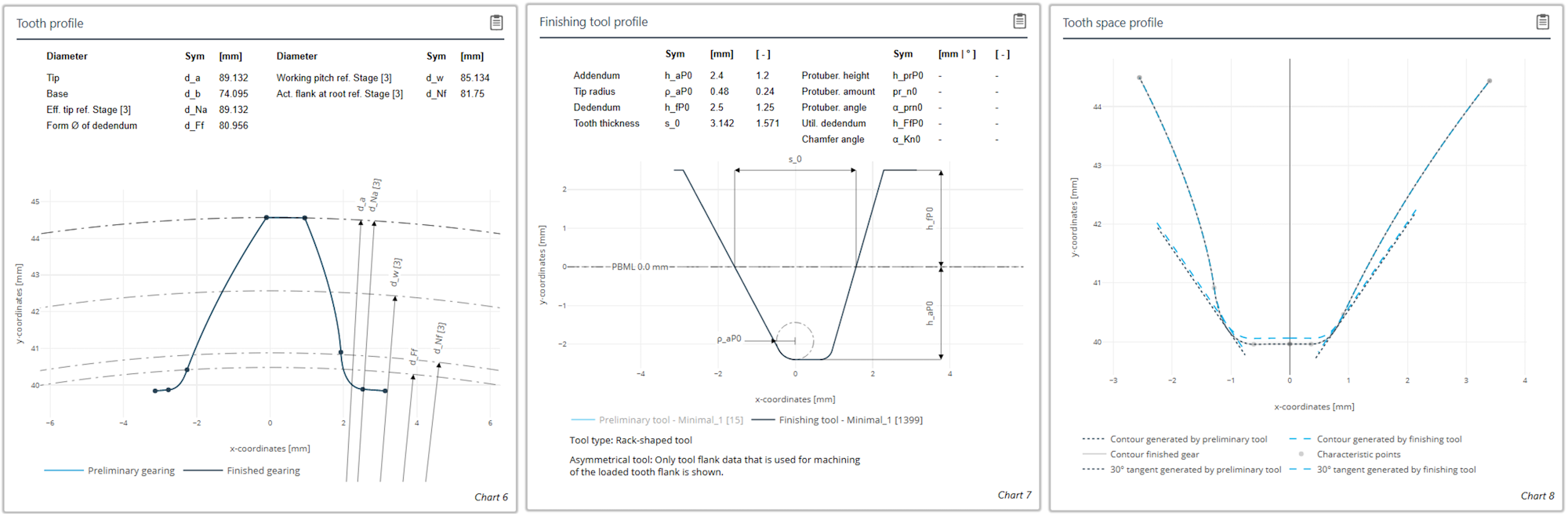
Diagrams for tooth and tool contour as well as the tooth gap geometry
Animation of asymmetrical gear mesh
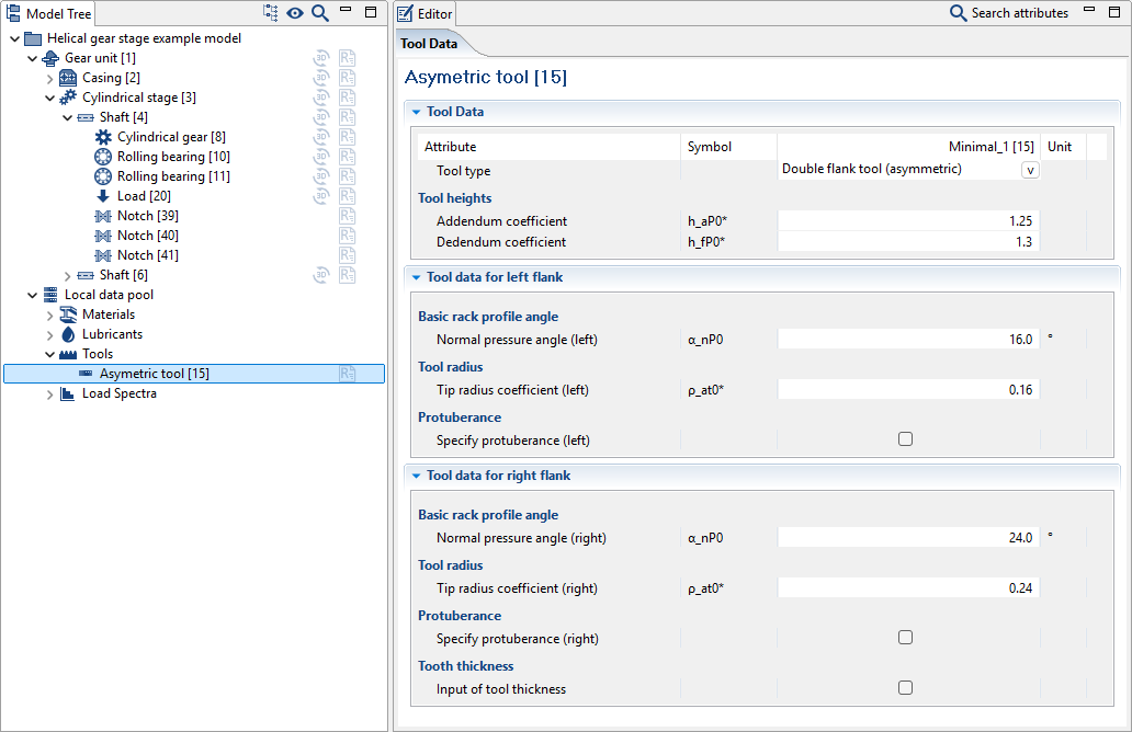
Input data for a two-flank tool. Different values can be specified for the pressure angle, tool tip radii, and protuberances for the left and right flanks of a two-flank tool.
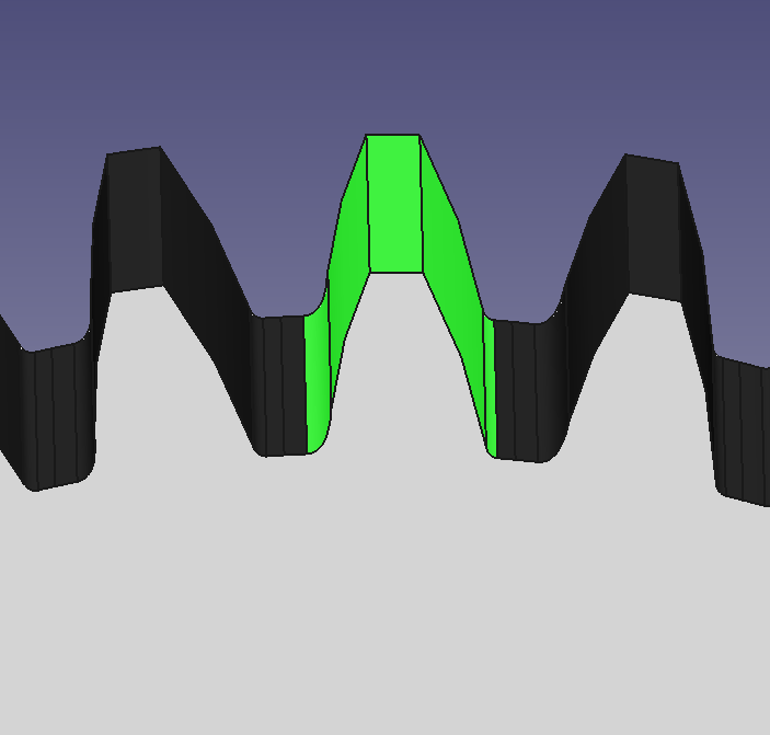
Asymmetric gears can be exported as CAD files.
New plain bearing models in EasyEntry to demonstrate new features
Calculation of a slow-running fixed segment bearing with wear
Calculation of a tilted pad bearing with hydrodynamic pockets and consideration of the thermal and mechanical behavior of the tilting pads using FEM.
Simplified geometry specification and geometry preview

To simplify the specification of the plain bearing geometry, a preview can now be shown in the Quick Results View.
Mixed friction & wear
Mixed friction states can now be considered in plain bearings. A wear simulation can also now be performed in individual plain bearing calculations. To do so, the duration of the simulation must be specified; it is then automatically divided into smaller time intervals. The corresponding amount of wear is determined for each interval, which then changes the gap geometry for the next time interval.
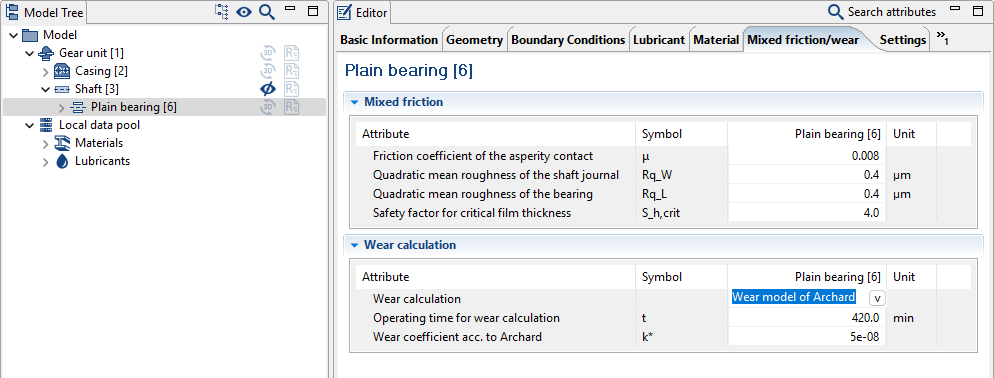
New "Mixed friction/wear" tab
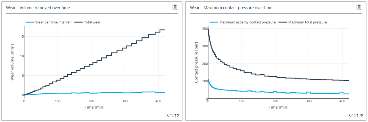
Progression of wear volume and contact pressure over the duration of the simulation.
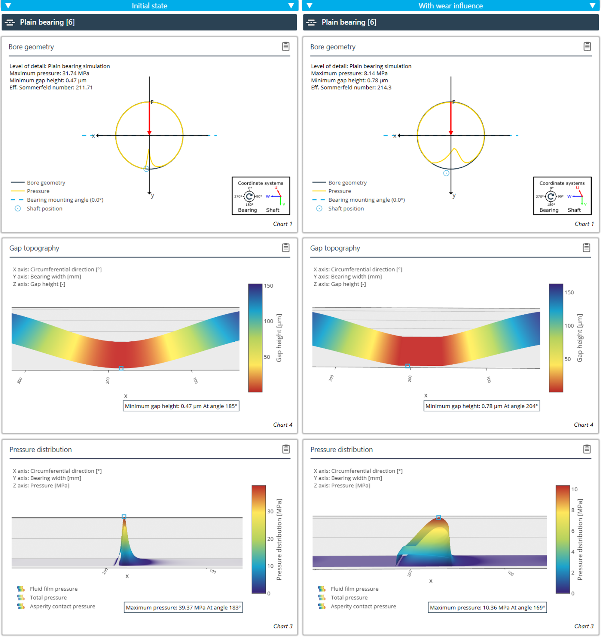
Comparison of the operating behavior of a plain bearing with and without wear.
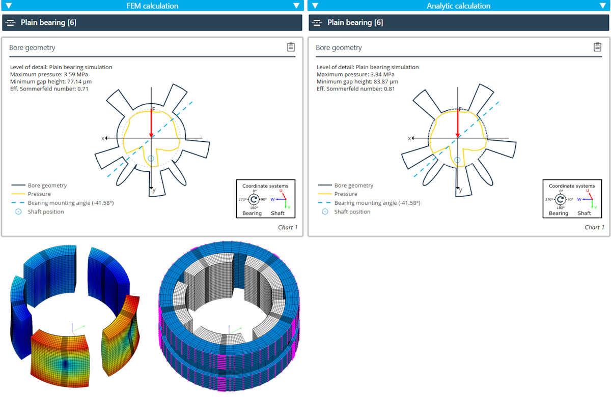
Comparison of FE-based tilting pad stiffness with the stiffness from the calculation as Hertzian contact.
Determination of the tilting pad stiffness
Three levels of detail are available for determination of the tilting pad stiffness:
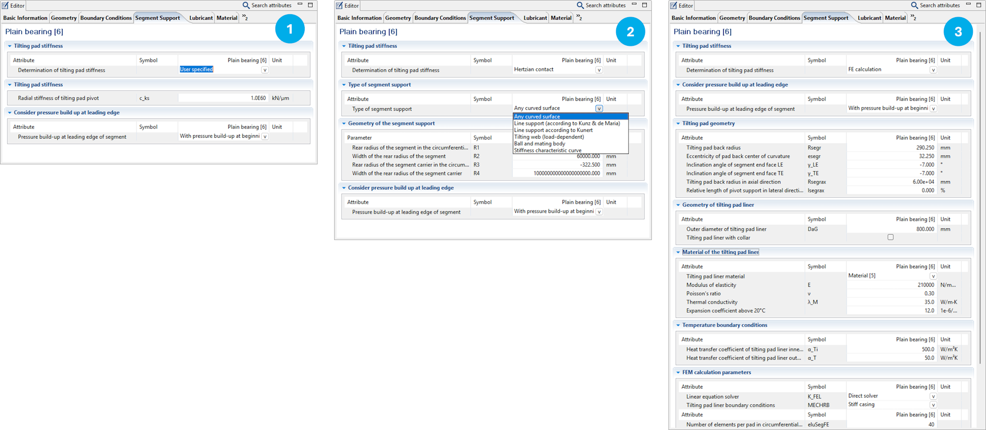
Manual specification of the stiffness
Modeling as Hertzian contact: Multiple calculation methods are available.
Using the internal FE module: An FE model of the tilting pad and the carrier are automatically created based on the user specifications.
Temperature boundary conditions - Fixed segment bearings
The Editor for specifying the temperature boundary conditions of fixed segment bearings has been made clearer.
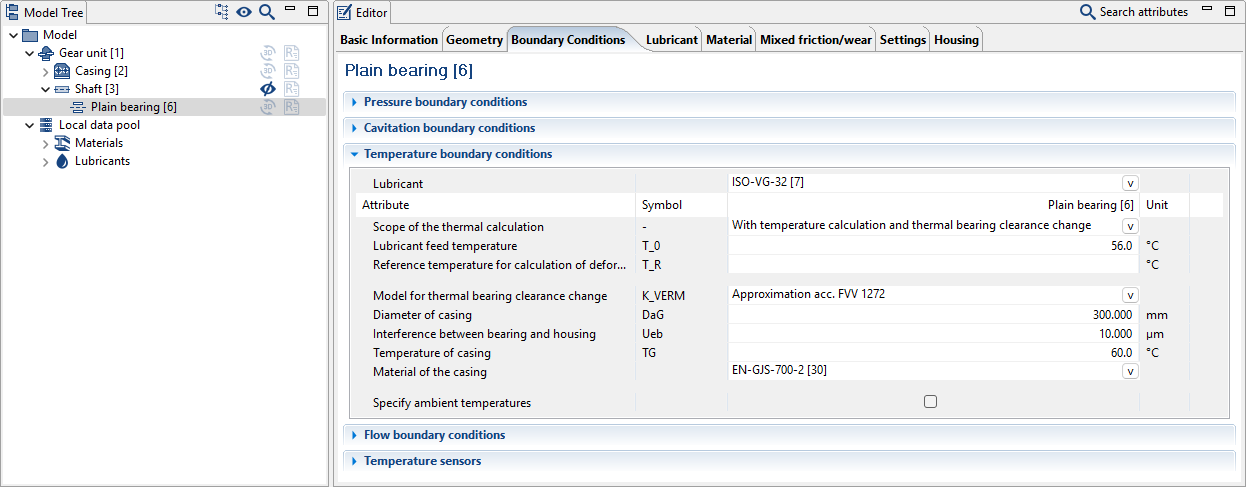
Default values for heat transfer coefficients
Optionally, ambient temperatures can also be specified
New: Improved consideration of the change to the thermal bearing clearance in accordance with FVV 1272
Temperature boundary conditions - Tilting pad bearings
The Editor for specifying the temperature boundary conditions of tilting pad bearings has been made clearer.
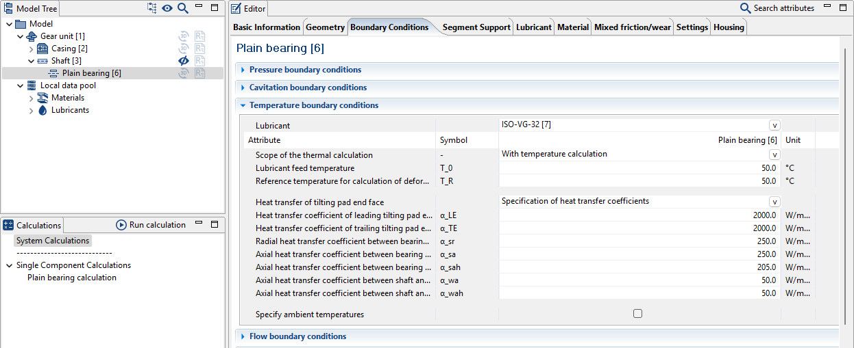
Optionally, ambient temperatures can also be specified
New: Heat transfer coefficients at segment end surfaces
New: Improved consideration of the change to the thermal bearing clearance from FE calculations
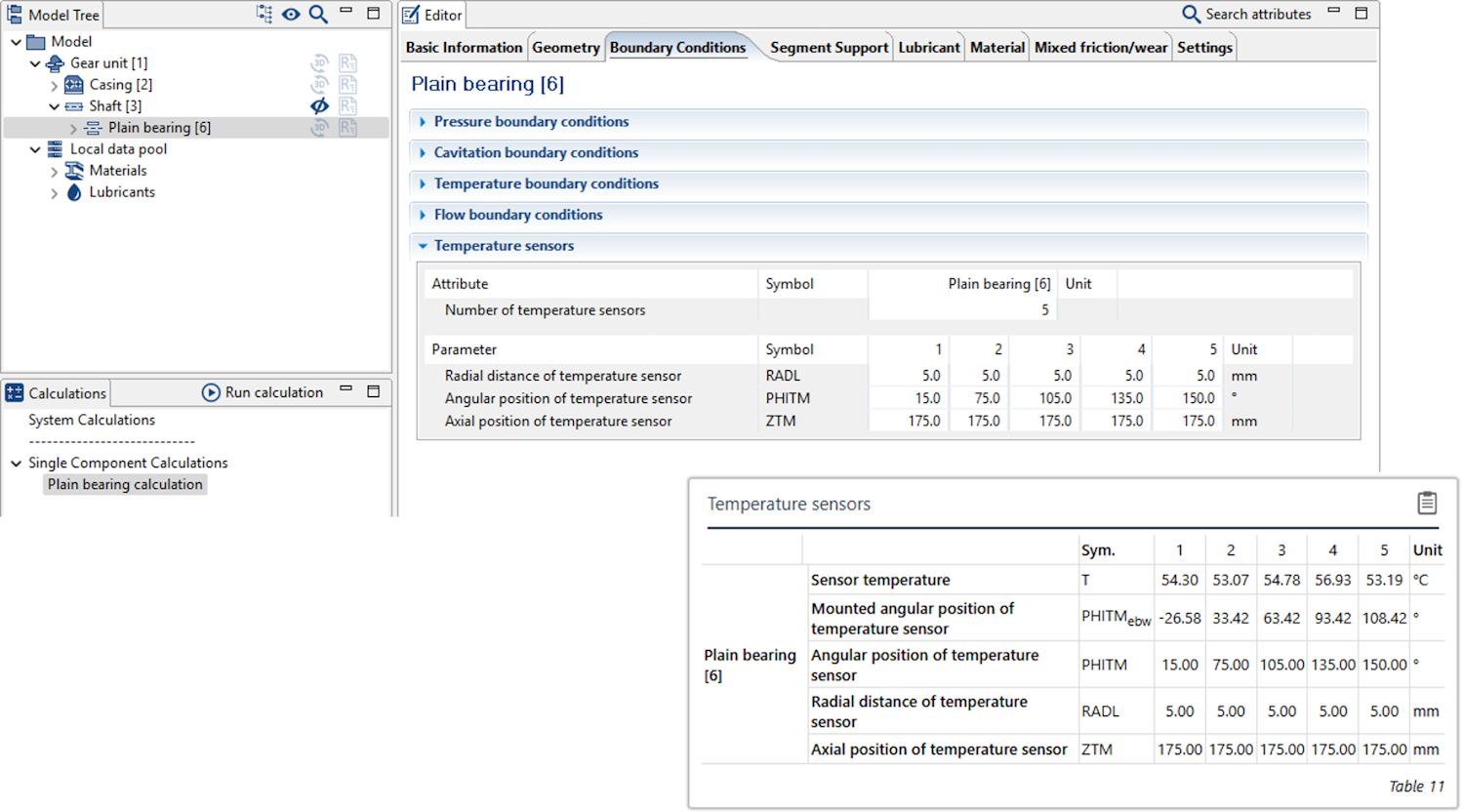
Temperature sensors
Evaluation points can now be specified for the temperature in the bearing.
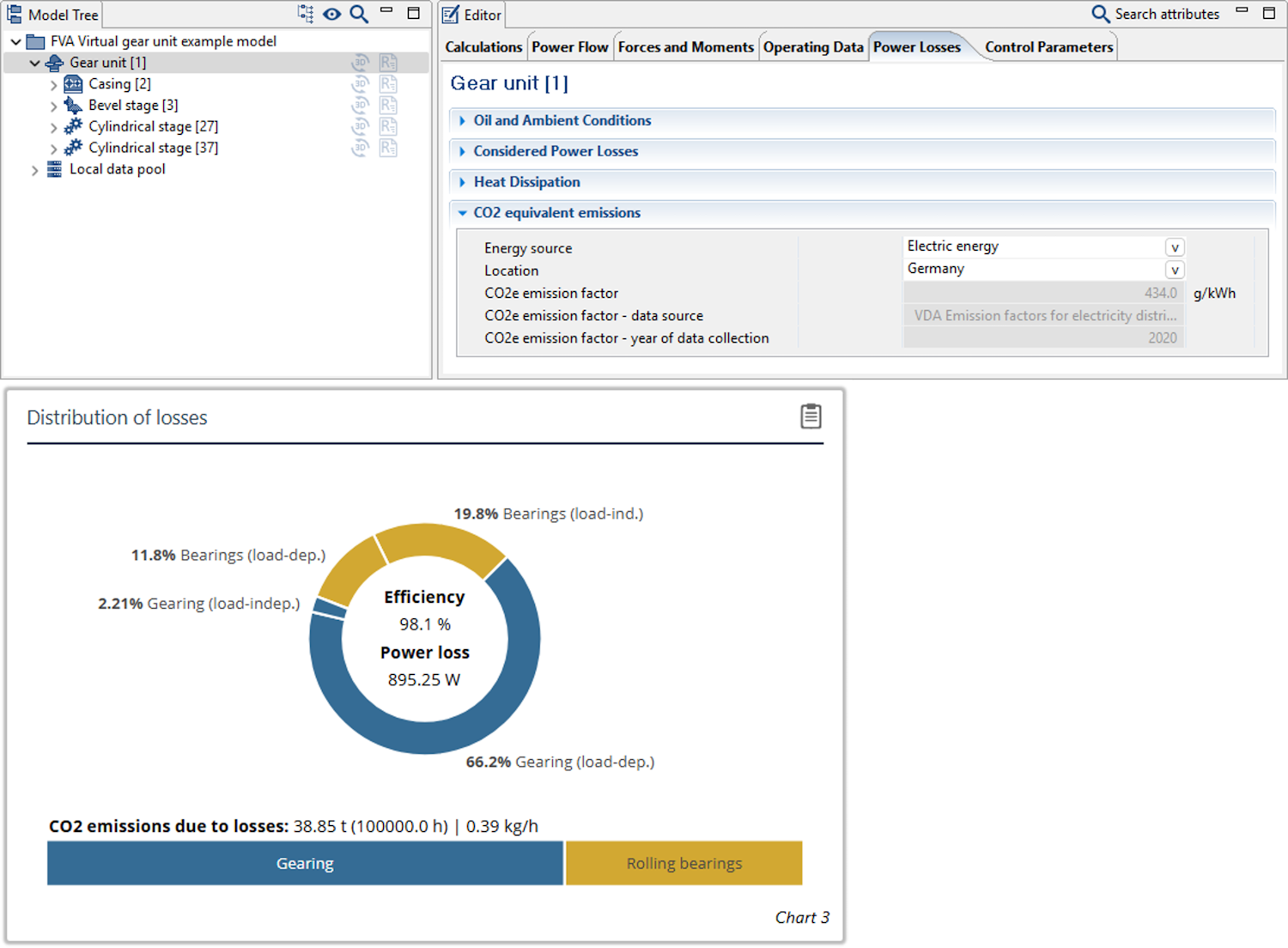
CO2e emissions resulting from losses in the gearbox can now be determined. The underlying emission factors are based on the VDMA Report "Emission factors for electricity, district heating, and fuels."
ISO 10300 (2023) load spectrum calculations
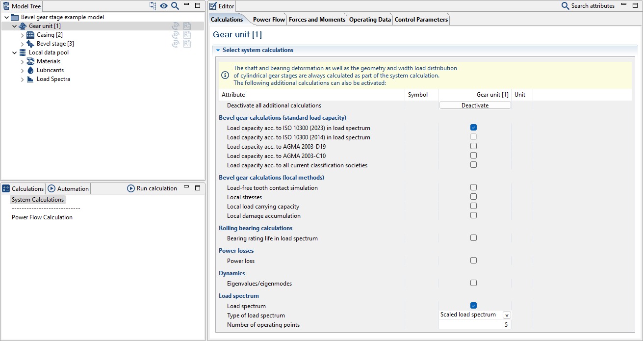
Load spectrum calculations can now be performed for bevel and hypoid gear stages in accordance with the current version of ISO 10300 (2023) as part of the system load capacity calculation.
Calculation of the fatigue strength of shaft notches has been expanded in accordance with the latest FVA Guideline "Shaft fatigue strength calculations" FVA 231 VII (FVA 321 for short). The guideline bundles the key results of the FVA 321 VI, FVA 700 I, FVA 353, FVA 467 I-II, FVA 579, FVA 802 I-II, FVA 840 and FVA 703 I research projects from the shaft-hub connections working group and makes them available as a comprehensive calculation process.
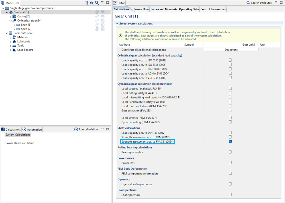
In the FVA-Workbench, calculation in accordance with FVA 321 for all notches in the gear unit can be activated as part of the system calculation.
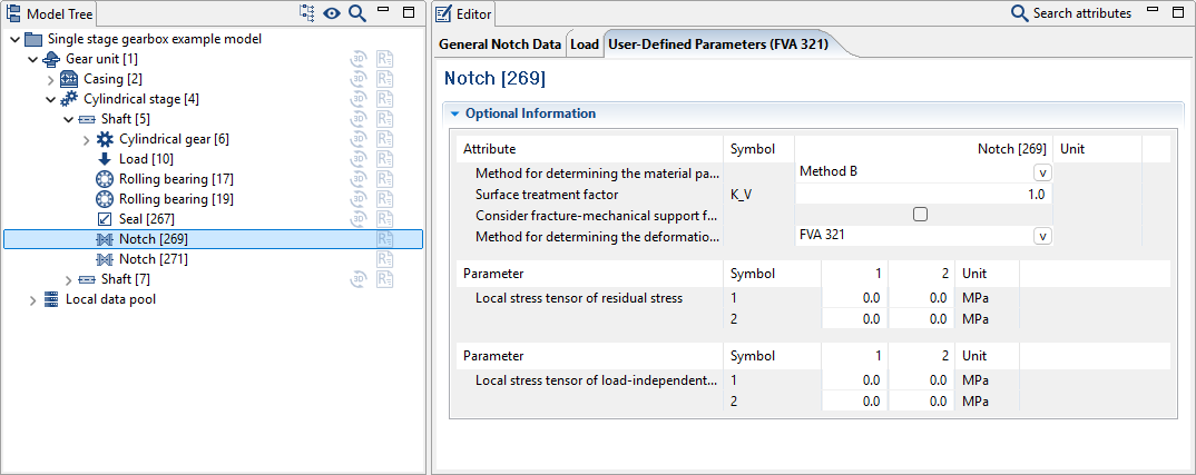
The FVA 321 calculation can be performed for all notches without additional input based on specifications provided for the calculation in accordance with DIN 743. Notch shapes with analytically determined stress concentration factors as well as FE-based stress concentration factors (KERBERT) are supported.
In addition to comprehensive default values, additional information can be specified for the individual notches, such as for better consideration of load-independent mean stresses or residual stresses.
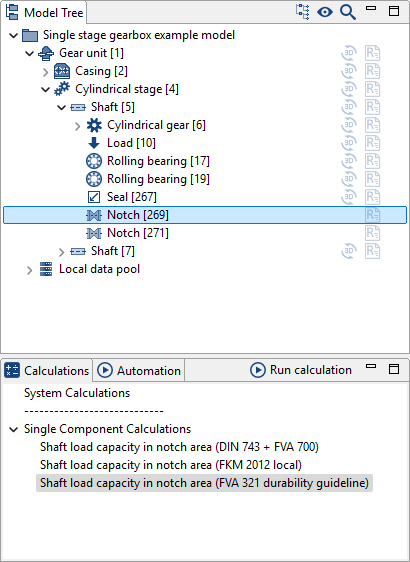
Individual component calculations are also available in addition to the system calculation
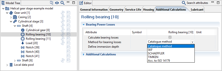
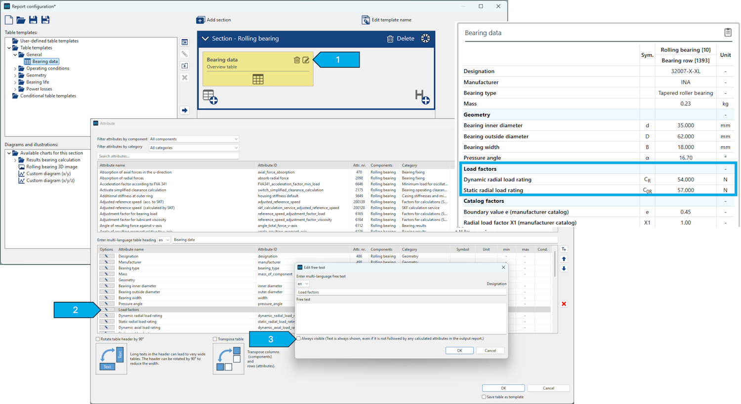
Methods for calculating bearing losses
The user can now select which catalog method is used for calculating rolling bearing losses. In particular, bearings with (internal) geometry specifications can also be calculated in accordance with catalog methods.
Extension of power loss calculation according to Schaeffler
The power loss calculation of oil bath lubricated rolling bearings using the Schaeffler catalog method now takes the oil level into account. The factors specified there apply to an oil level that reaches to the center of the lowest rolling element. At higher oil levels, f0 can increase up to three times the table value.
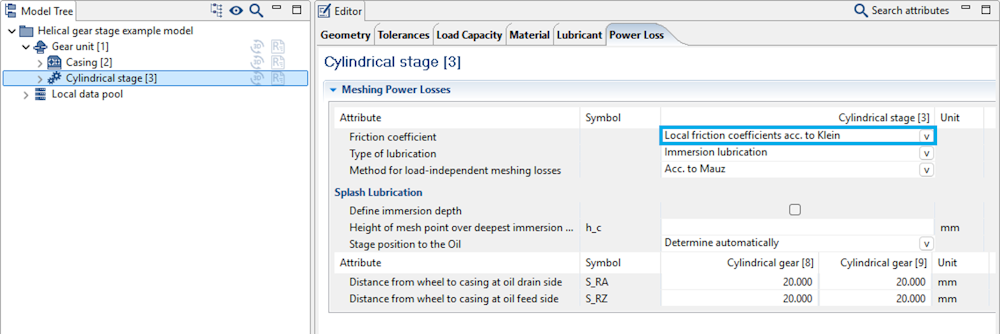
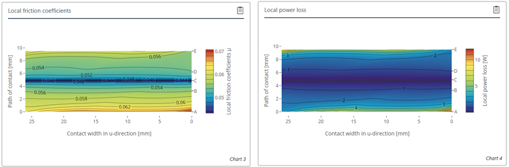
Local friction coefficients in the power loss calculation
The KLEIN method can now be used for calculation of the load-dependent gear losses of cylindrical gears.
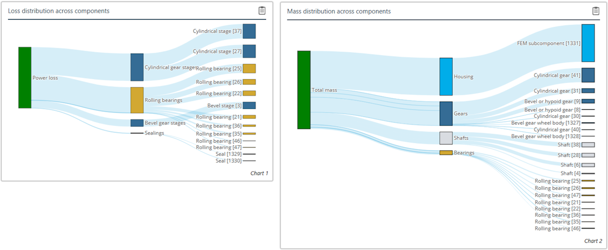
Sankey diagrams
The distribution of the power loss and the mass per component can now be visualized with two new Sankey diagrams.
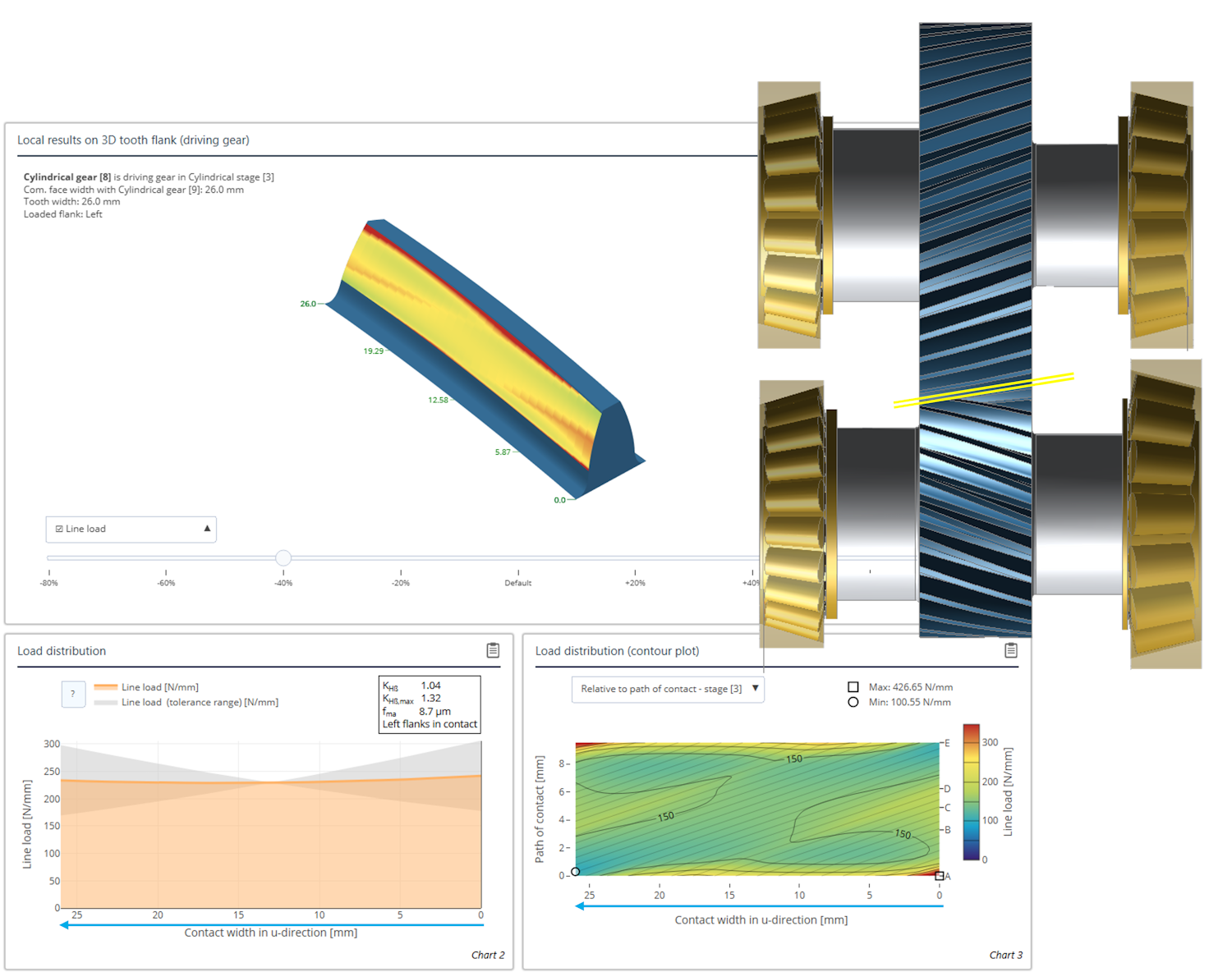
Results over the common face width
The x-axis of all diagrams which show results over the common face width now take the normal direction of the flank into consideration. The diagrams are mirrored so that they correspond to a view of the gear mesh from above. This greatly simplifies comparison with load or damage patterns.
Scroll position in reports
The current scroll position in the report is now highlighted in the component tree. This makes it easier to navigate within lengthy reports.
Subheadings in tables
Subheadings in reports are now hidden by default if they do not contain any attributes. This can be modified in the report configurator.
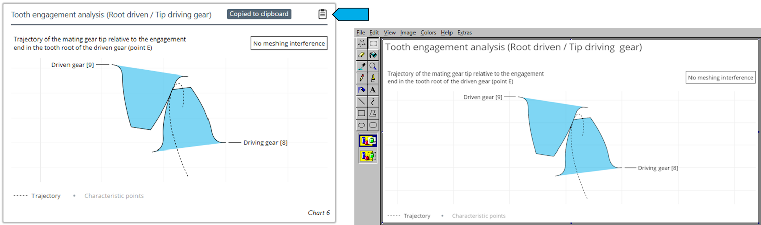
Copying diagrams to the clipboard
As with tables, diagrams can now be copied to the clipboard.
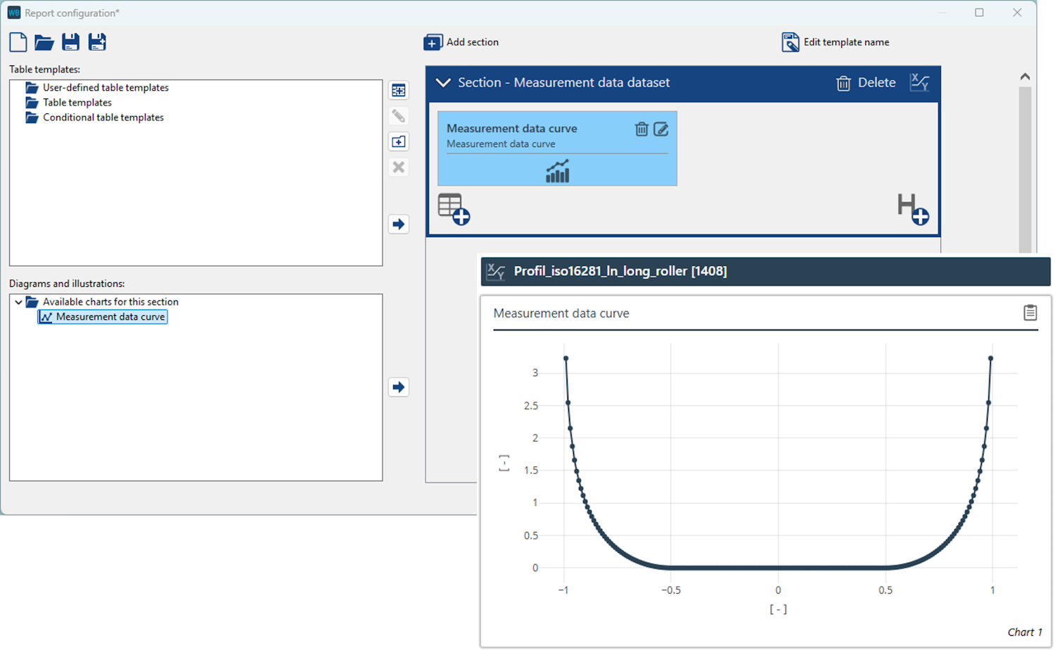
Diagrams for measurement data
Measurement data, such as bearing profiles, can now be displayed as diagrams in reports.
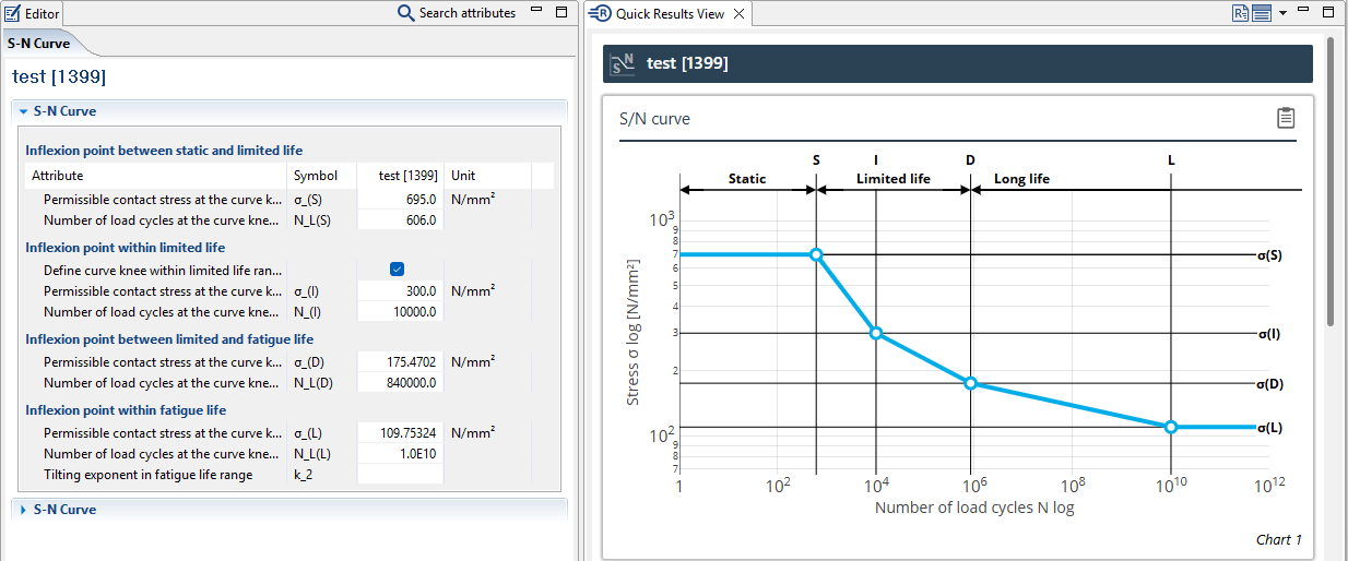
Woehler S-N curves
The Editor for specifying Woehler line input data has been revised. A new diagram for representing Woehler lines was also created.
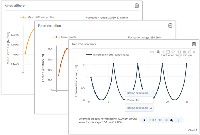
Gear excitation diagrams
Diagrams for displaying transmission deviation, force excitation, and gear stiffness have been expanded. It is now possible to switch between visualization of the rolling path and pitch.
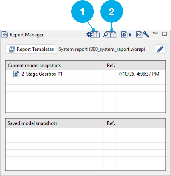
(1) Variant generator
(2) Variant comparison
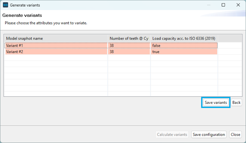
Variant generator
Management of data created during variant generation has been greatly improved. Thanks to more efficient memory management, significantly more variants can be generated without placing an undue load on the system memory.
The number of variants is now shown in "All combinations" mode.
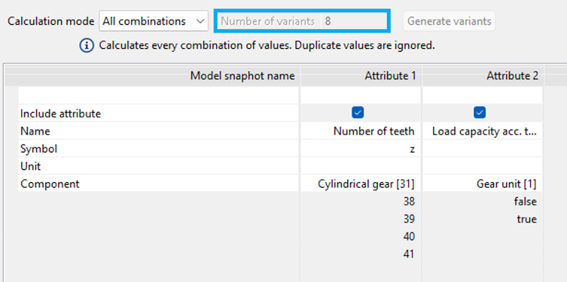
If a variant calculation is terminated before completion, the variants that have already been calculated can now be saved as model snapshots.
If a variant is outside the permissible range, the cells are highlighted in red.
Variant evaluator
Right-click on a table in the variant evaluator to copy the contents to the clipboard for simpler analysis.
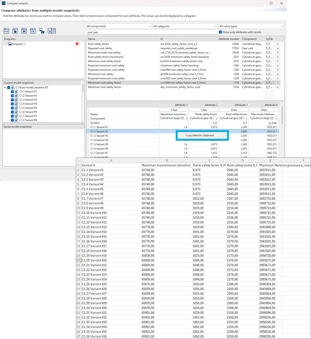
If a row of a table is selected, the corresponding curve is highlighted in the diagram. Similarly, clicking on a curve highlights the corresponding row in the table. This behavior has been optimized.
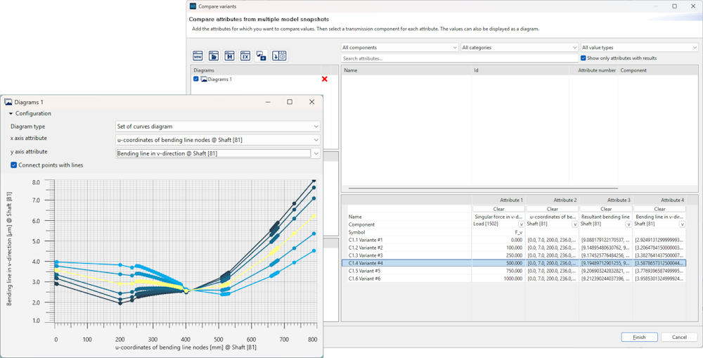
If an attribute value in a snapshot was not calculated (null), it was previously shown as 0 in diagrams. This error has been corrected.
In some cases, values on the x-axis of diagrams were shown multiple times. This error has been corrected.
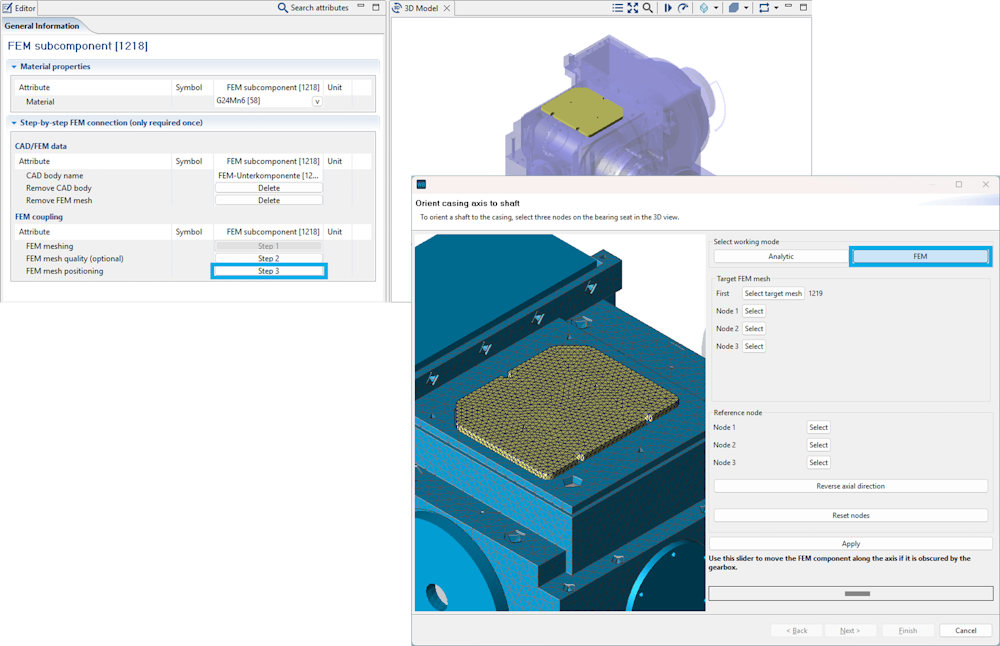
The assistant for positioning FE components has been revised and extended. With the new "FEM" mode, components without specific characteristics such as bores or holes can also be aligned to the analytical model. This makes it possible to easily and precisely position components such as bearing bushings or covers.
Undo/redo functionality has been added to the shaft contour editor in the 2D modeler. Changes can be reversed using CTRL + Z, and reversed actions can also be restored via CTRL + Y.
Both periods (.) and commas (,) can now be used as decimal separators in input fields.
An error in the specification of the width of the thrust collar of thrust bearings has been corrected.
The new multiPrompt() scripting function can be used to query the user while the script is running. This supports input fields for text and numbers, drop-down menus, file and folder selection, and checkboxes.
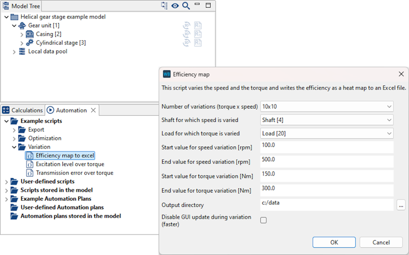
The "Efficiency map to Excel" example script has been modified to use the multiPrompt() function. Instead of multiple sequential queries, all requested data is now included in a single dialog.
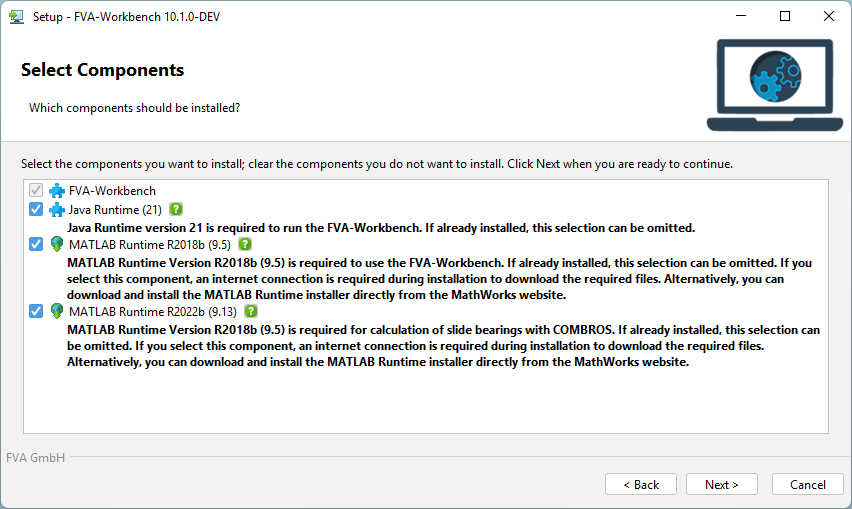
To keep the installation file as small as possible, individual FVA-Workbench software components can now be downloaded during the installation process. These components are:
- MATLAB Version R2018b (9.5) – Required for various calculations in the FVA-Workbench.
- MATLAB Version R2022b (9.13) – Required exclusively for plain bearing calculations with COMBROS.
Alternatively, both MATLAB versions can be downloaded directly from the MATLAB website: https://www.mathworks.com/products/compiler/matlab-runtime.html
The position of the light source in the 3D Model can now be adjusted using latitude and longitude.
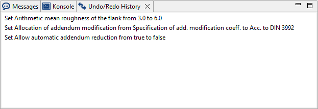
The undo/redo history has been expanded to show both the previous and subsequent values for each change. This makes it simpler to track the editing steps.
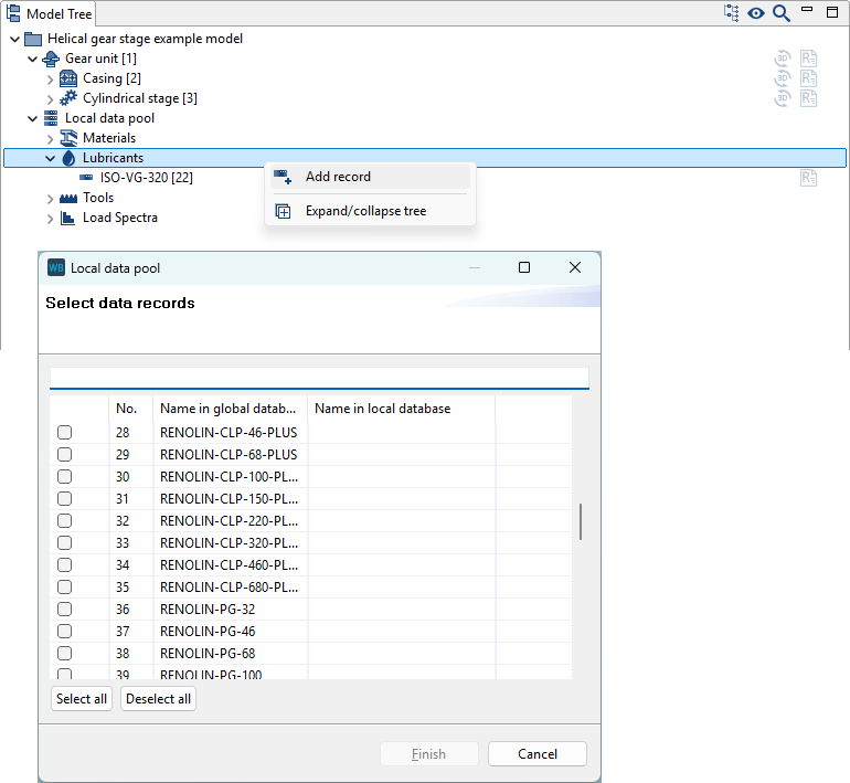
The FVA-Workbench has been expanded to include FUCHS gearbox lubricants.
The SKF catalog bearing database has been updated to the current status as of 02.06.2025.
NSK bearings are now available in the catalog bearing database.
Bugfixes/improvements
An error in the calculation of the planetary safety of planet-ring gear meshes in the DIN 3990 load spectrum calculation has been corrected.
The gear tolerances (according to tables) for cylindrical gears are no longer calculated from the geometry (diameter, width, module) and then rounded. Instead, the values are now determined directly from the standard tables. The exact values calculated according to the formula are also output. These values are still used for the calculation.
When "Geometry from DIN 5480 Table" is selected in the spline connection input wizard, the number of teeth is now determined directly from DIN 5480-1 Table 1. If the specified reference diameter or the module is not included in the table, an error message is displayed.
Bevel gear calculations: New BECAL Version 6.5.2
An error in the calculation of collision points between the flank and root of the mating gear has been corrected. Points that are not located on the transition line can now be detected once again.
Verification of whether the specified gears "fit together" (module, effective profile angle) has been revised and now only leads to an abort in extreme cases. A warning is displayed.
An error in the base point calculation that could lead to gaps in the contact pattern has been corrected. An earlier bugfix (see v6.5.0_185) was ineffective.
Import of bevel gear machine setting data
The value of the "Finishing" attribute is only changed when importing machine setting data or with geometry design in accordance with ISO 23509 when KIMoS neutral data with specified finishing is imported.
Worm gears: An error in the determination of the service life factor in the calculation of the root safety in accordance with DIN 3996 has been corrected.
Automatic specification of a low value for the torque of freely rotating planet carriers in Wolfram gear units now works more reliably.
An error in the calculation of the planetary safety of planet-ring gear meshes in the DIN 3990 load spectrum calculation has been corrected.
An error with the transfer of results for individual planetary bearing calculations has been corrected.
An error in the 3D representation of the gear mesh of planetary stages has been corrected.
User data such as report templates, components, etc. are stored in the user's documents folder. Previously, a system-side redirect of this directory was ignored, and the data was stored in the original document folder. Data is now correctly stored in the location specified in the redirect.