FVA-Workbench 10.0.0
Features
The 2D Modeler projects the existing gearbox model onto a plane, which simplifies the modification of geometries, positions, and other properties. This is particularly beneficial for shaft modeling. As with drawing software, the shaft contour can be edited as a polyline in which individual or multiple points can be modified simultaneously. Edges can also be moved to the desired position using drag & drop.
Snap functionality can be used with all drag & drop operations to automatically align to a grid or other components. Shaft drawings can also be added as background images.
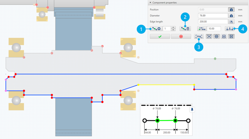
As with drawing software, the shaft contour can be edited as a polyline in which individual or multiple points can be modified simultaneously. Edges can also be moved to the desired position using drag & drop.
(1) Add node to edge
(2) Delete node
(3) Load background drawing
(4) Extrude shaft section
The variant generator is a wizard that can be used to vary multiple attributes of the gearbox model simultaneously. The varied attributes can be calculated row by row or using a full factorial approach. Scalar parameters, such as the helix angle of gears or the oil temperature of the gearbox, can be varied. However, variants with different bearings or materials can also be calculated. The results for the individual variants are saved as model snapshots and can be analyzed using the variant comparison functionality.
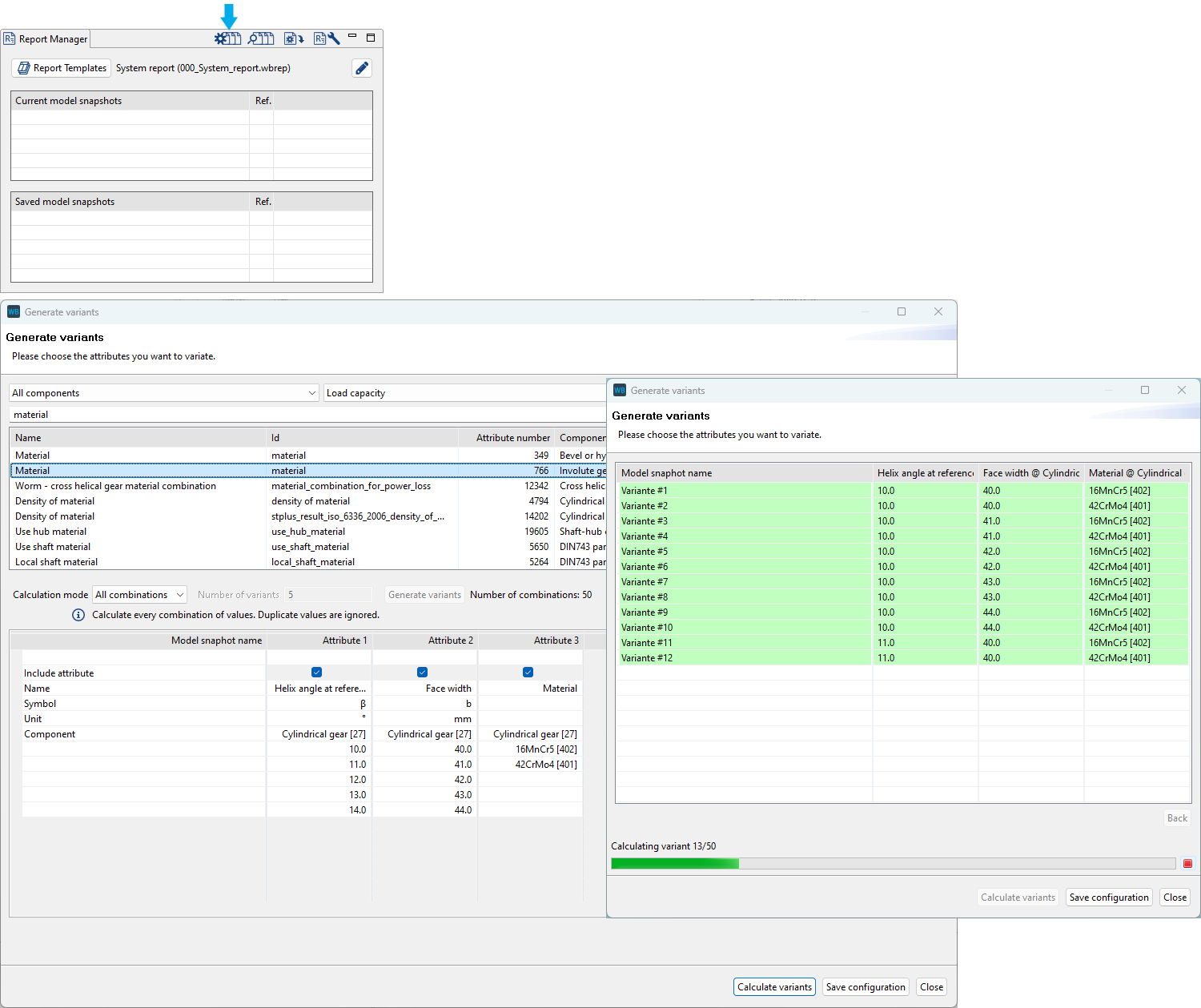
In this example, the helix angle and face width of a gear are each varied in five steps. Two different materials are also considered in the variation. The combination of these three parameters results in 50 calculation variants.
The Quick Results View is based on the FVA-Workbench's established reporting module and provides an immediate view of calculation results. The results for a selected component are presented in tables and diagrams as soon as a calculation is complete or a model snapshot is loaded. This makes it possible to see the effects of changes to the gearbox model at a glance, without the need for a full results report.
Calculation results are displayed immediately for a selected component. Various different outputs can be selected.
The mass and torsional inertia of each gearbox component is now calculated as part of the system calculation.
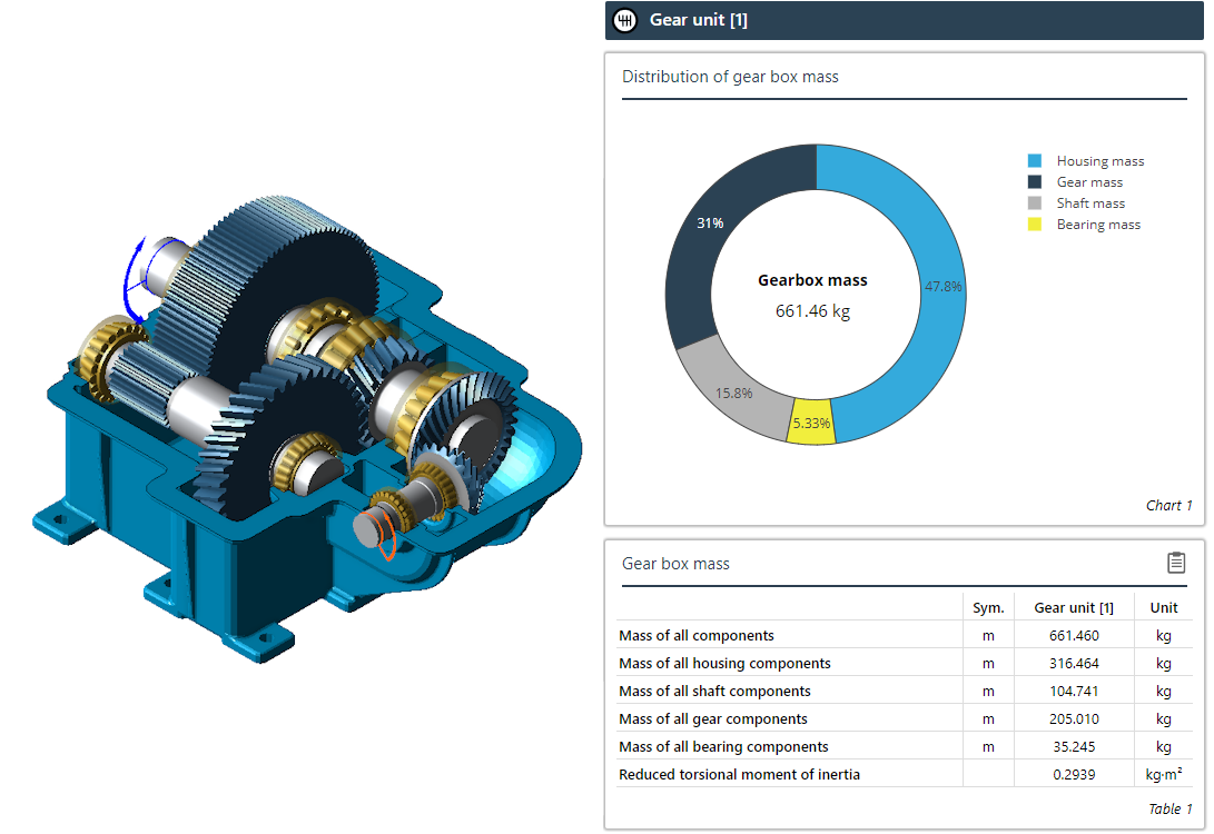
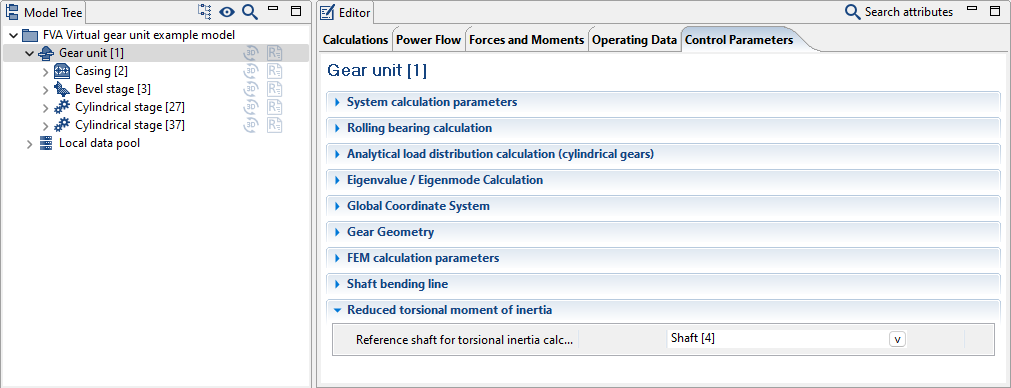
Specification of a reference shaft to be used for the calculation of the reduced torsional inertia. The component inertias are then reduced to this shaft in order to calculate the torsional inertia of the entire gearbox.
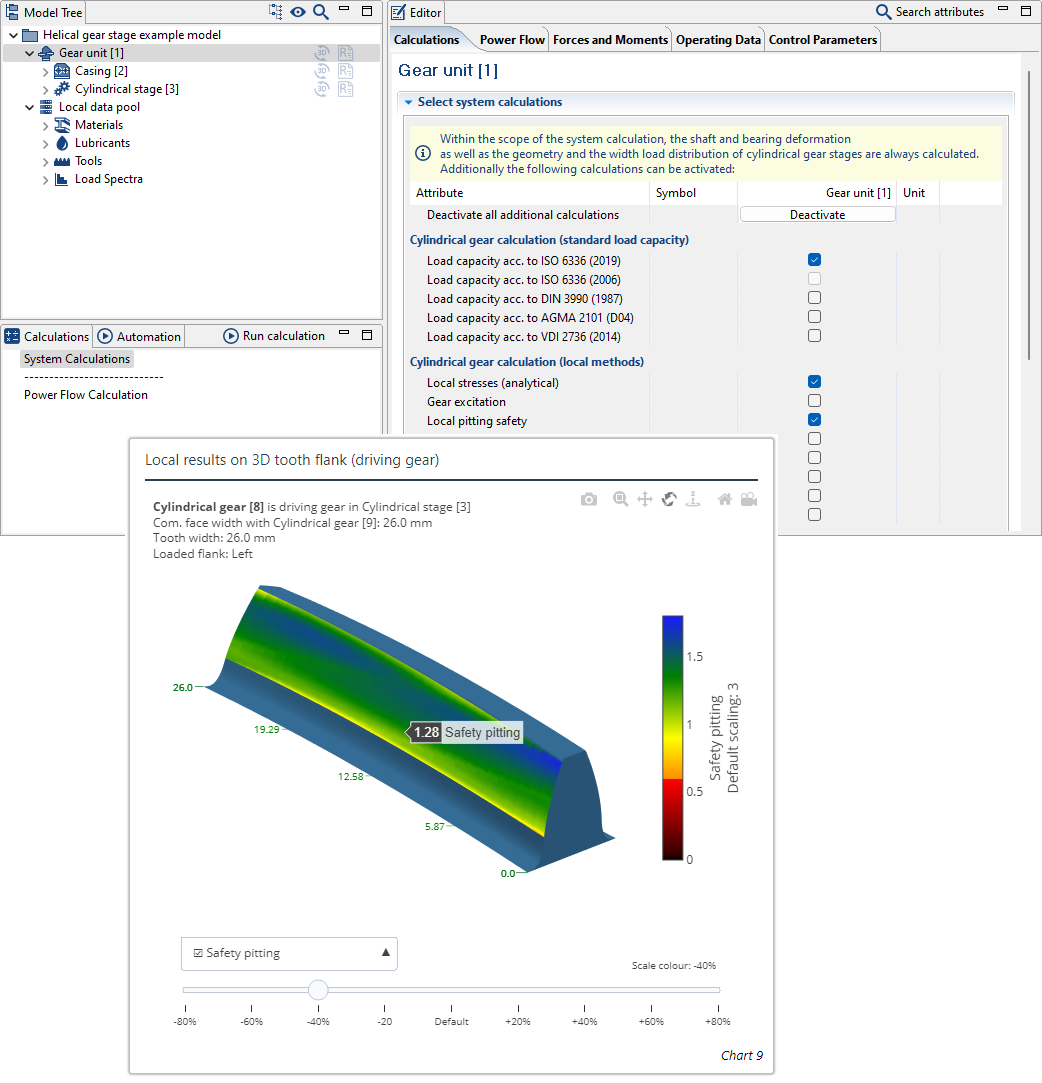
The local calculation of the pitting resistance according to FVA 411 was developed and tested for bevel and hypoid gears, which enables local calculation of the pitting fatigue strength. This calculation method has been modified and made available for cylindrical gears, which enables local evaluation of the pitting resistance for a specified load case. The FVA 411 calculation method is based on the formulas according to ISO 10300. For consideration of the local meshing conditions, the influencing factors used in the formulas are determined with local values.
Skiving can be used for cost-effective production of high-quality external and internal cylindrical gears. The goal of the ongoing FVA Project 1009 I is to integrate skiving into the FVA-Workbench as a new method for generating the profile of cylindrical gears in order to facilitate the simple design and recalculation of skived cylindrical gears.
Generation of the deviation-free nominal profile is already implemented in FVA-Workbench 10. The nominal profile can be used to determine the local gear stresses on the flank and in the tooth root.
The required parameters for calculating the tooth root safety in accordance with ISO 6336 are also derived from the nominal contour. Generation of the actual geometry with deviations using a manufacturing simulation based on the tool and machine data will be added in a future version of the FVA-Workbench.
The diameter values for the meshing points A to E are now available as attributes. For example, this can be helpful to improve the design of the start of the tip relief. A distinction is made between load-dependent and load-independent. The attributes can be displayed in output reports or retrieved via scripting.
Attribute IDs:
diameter_point_a, diameter_point_a_load_dependent
diameter_point_b, diameter_point_b_load_dependent
diameter_point_c, diameter_point_c_load_dependent
diameter_point_d, diameter_point_d_load_dependent
diameter_point_e, diameter_point_e_load_dependent
Profile generation by injection molding, sintering, broaching
For cylindrical gears where the tooth root radius is specified by the user, the tooth root stress can now be calculated according to ISO 6336 Part 3.
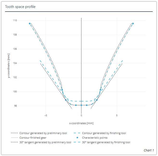
The tooth space geometry diagram has been expanded to include visualization of the 30°/60° tangent.
The calculation of notches in the tooth root for ISO 6336 has been improved.
The limit value for tooth root notch detection and meshing interference can now be specified.
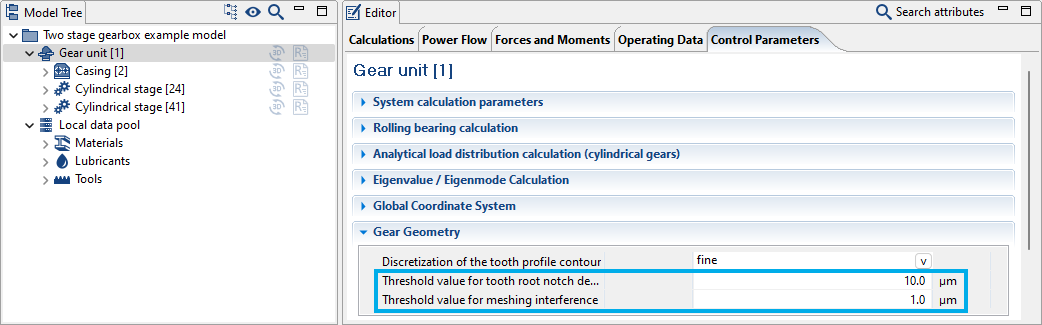
The limit value for the notch depth was previously 1 μm, the new default value is 10 μm. This should be adjusted for small gears.
The mean coefficient of friction can now be specified for ISO 6336-20.
An error in the power loss calculation of planetary stages has been fixed.
The gearing tolerances according to tables were previously determined by rounding the values calculated according to the formulas in DIN 3962 or ISO 1328. From now on, the actual values given in the tables of these standards will be output. The values calculated according to the formulas will continue to be used in the load capacity calculations.
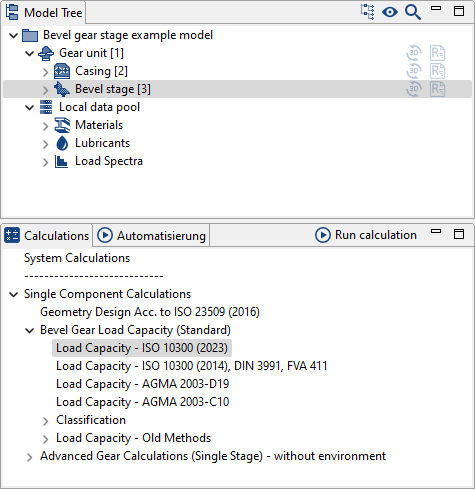
Standard bevel gear calculations according to ISO 10300 (2023) are now available.
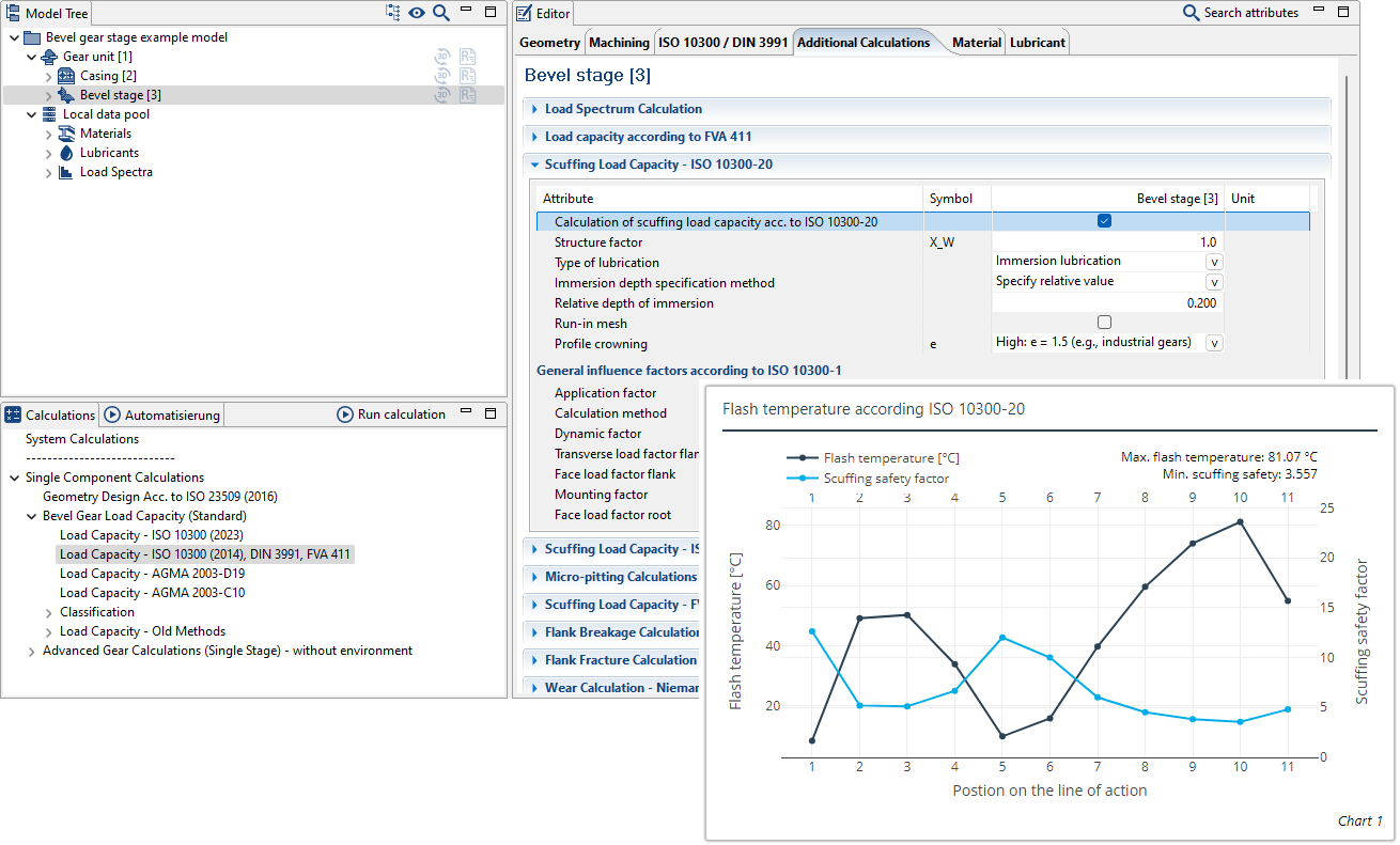
The scuffing safety calculation in accordance with ISO 10300-20:2021 is now available as an additional calculation for the ISO 10300 (2014) load-bearing capacity calculation.
New KNplus version 5.1
New BECAL version 6.4
For the scuffing calculation in accordance with ISO/TS 6336-21, the calculation kernel now correctly recognizes the input of the scuffing torque as an alternative to the scuffing force level in the lubricant.
Specification of the lubrication type, lubricant factor X_S, and the immersion depth for splash lubrication is now consistent for standard and local calculation methods. The type of lubrication must must now be specified, as the default assignment within the calculation kernels is not consistent.
The bevel gear standard calculation according to AGMA 2003-D19 is now available for system and individual calculations.
The attribute help for bevel gear standard calculations according to AGMA 2003-C10 and AGMA 2003-D19 has been revised and expanded.
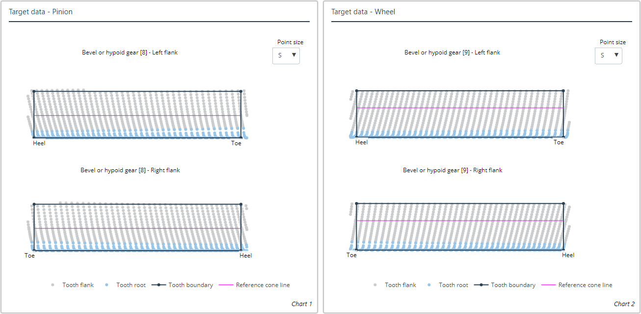
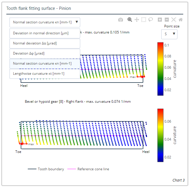
New diagrams are now available for the nominal data (including rim) of the pinion and wheel gear for the flank and root.
The diagrams for visualization of the flank fitting surfaces have been extended to include the normal and tangential curvatures.
Geometry calculations for spur gears can now be performed according to ISO 23509 based on a spherical involute for gears manufactured and printed using primary molding and forming technology.
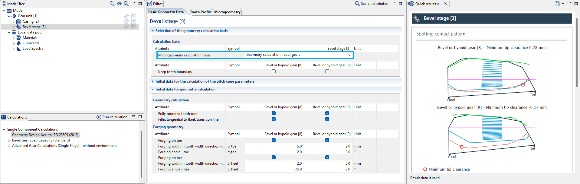
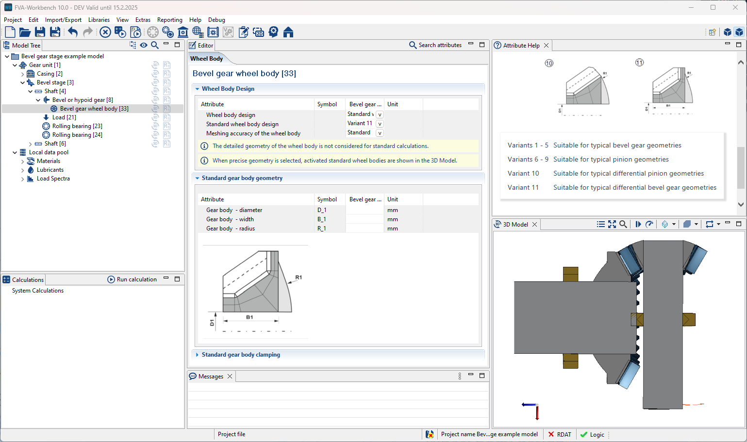
Parametric standard gear bodies can now be considered for differential bevel gears.
Meshing of FEM sub-components in multi-part housings
For multi-part housings, the CAD bodies of the individual parts can now be individually imported and meshed. Each net can then be positioned separately.
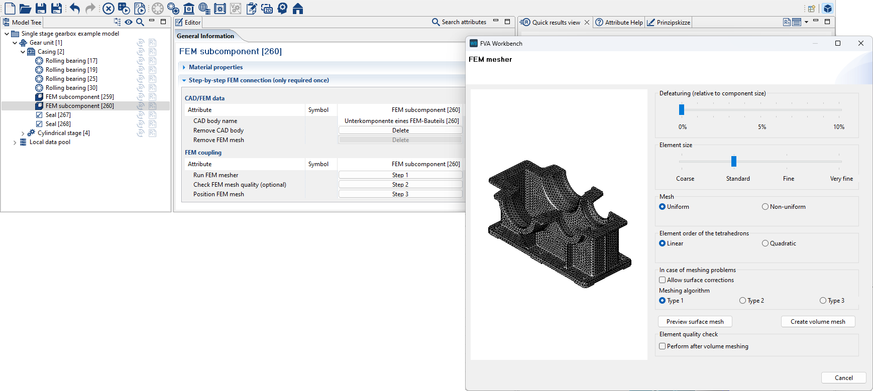
The individual CAD bodies can now be meshed with individual parameters.
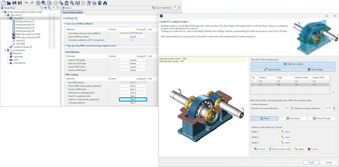
Assistant for snapping contact nodes in multi-part housings
The wizard has been revised and now enables the snapping of knots on both surfaces and cylindrical surfaces. The user interface has also been optimized.
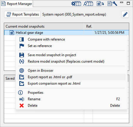
It is now possible to save result reports directly as PDF files. In addition, the scripting function generateReport() was extended by the “format” parameter.
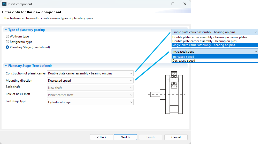
When adding a free planetary stage, basic definition of the design of the carrier and the mounting direction are now possible. Some default values have also been added.
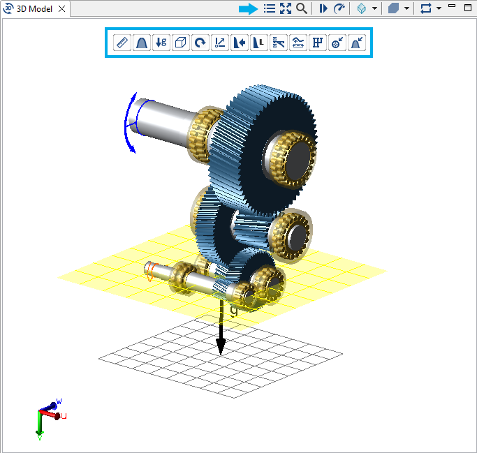
The buttons for displaying calculation results in the 3D Model have been removed from the right-click menu and moved to a separate toolbar.
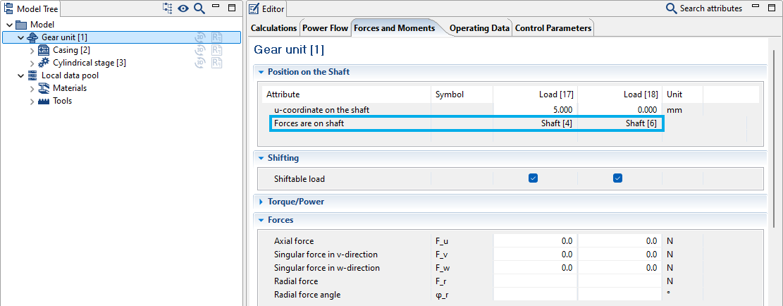
The "Forces and moments" tab now displays the shafts on which the loads are located.
Adding attributes to tables in the report configurator has been improved. Attributes can now be inserted after the selected row and moved using drag & drop.
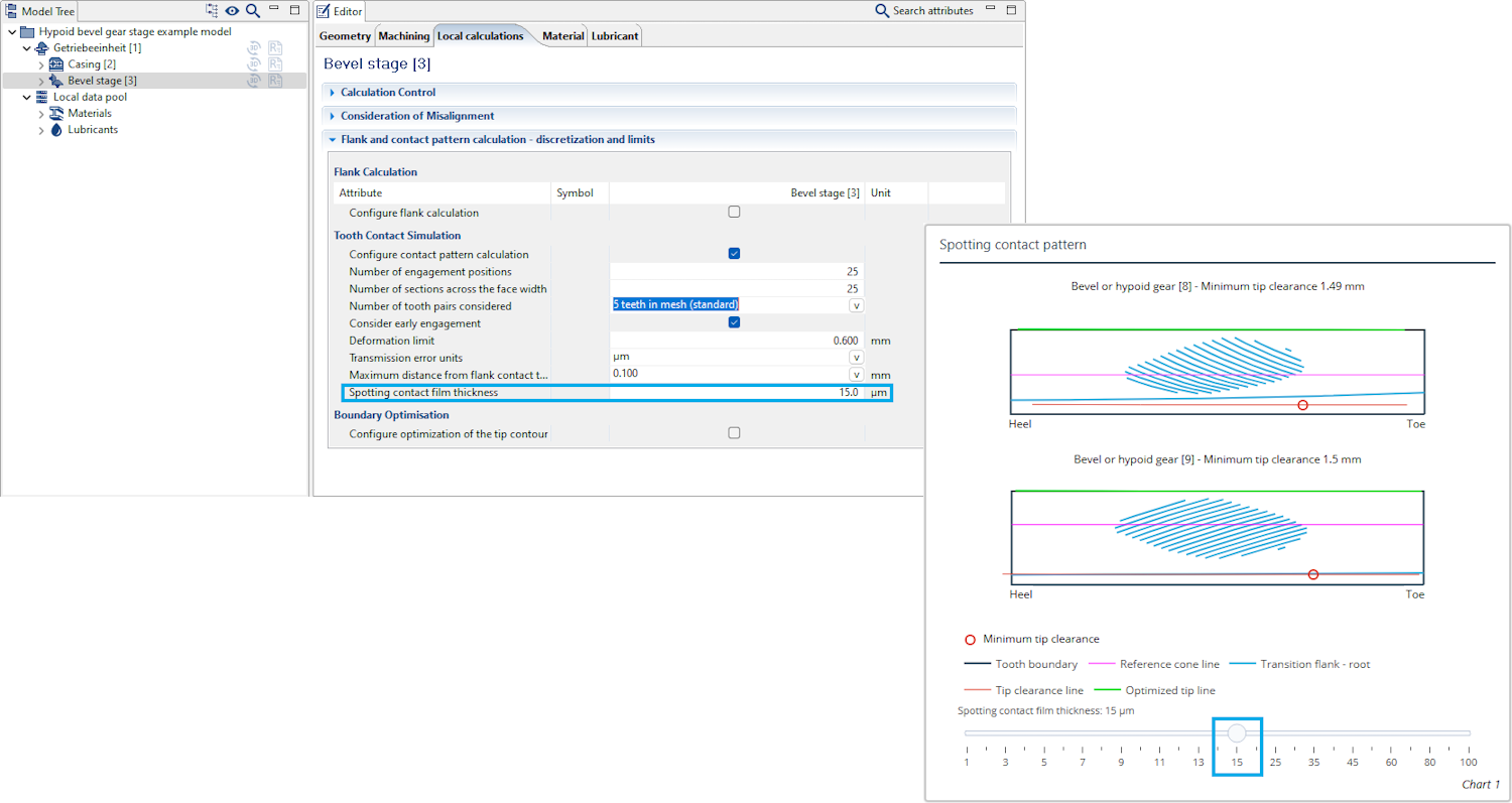
The standard spotting film thickness displayed in the report for bevel gear stages can now be specified.
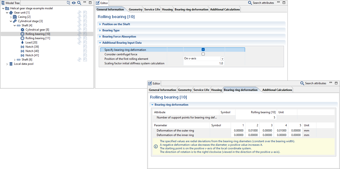
The input editor for bearing ovalization has been revised.
REXS version 1.7 is now supported.
The new scripting function validateRexsModel () allows REXS files to be validated via script.
Consideration of the impact factor and service factor have been adapted to follow common practice (impact factor for assessment against static failure and service factor for assessment against fatigue failure) when using DIN 743 and the FKM Guideline.
The way the LDA+ calculation kernel is initiated when calculating according to the FKM Guideline with nominal stresses (FKM Nominal) has been optimized to ensure correct results in cases where the sum of the mean stresses of the normal stresses is negative.
The calculation of the permissible bending moment of tapered interference fits in the presence of a critical diameter ratio in accordance with DIN 7190-2 has been modified. In addition, a warning message is issued in such a case.
An error in the control of COMBROS R with detailed segment support has been fixed.
A bug has been fixed - for plain bearings that are considered in the system calculation as linear stiffness with clearance, a subsequent plain bearing simulation with Combros is now possible.
It is now possible to freely select which catalog method should be used to calculate the losses of a rolling bearing. In particular, bearings with (internal) geometry specifications can also be calculated using a catalog method.
An error has been fixed when considering concept bearings with clearance in the overall system.
Tooth root stresses according to method A (determined from BEM) can now also be taken into account in the load spectrum.
The SKF bearing catalog has been updated (Edition 12-2024)
SKF frictional torque calculation: The determination of the factor S_1 for deep groove ball bearings of series 63 has been corrected.