Load spectra
Two different types of load spectrum calculations are available in the FVA-Workbench.
Figure 9. Scaled load spectrum 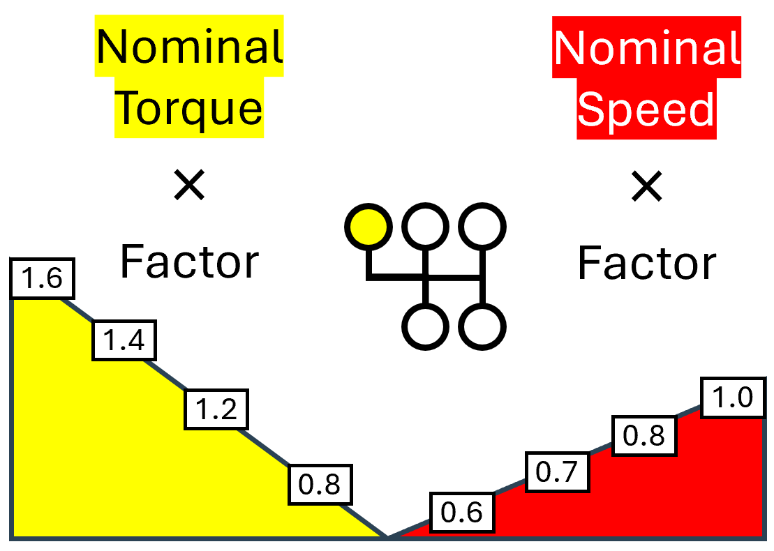 With scaled load spectra, the nominal power flow is multiplied by the speed and torque factors specified in the load spectrum. A load spectrum can be assigned to each gear selection. | Figure 10. Flexible load spectrum 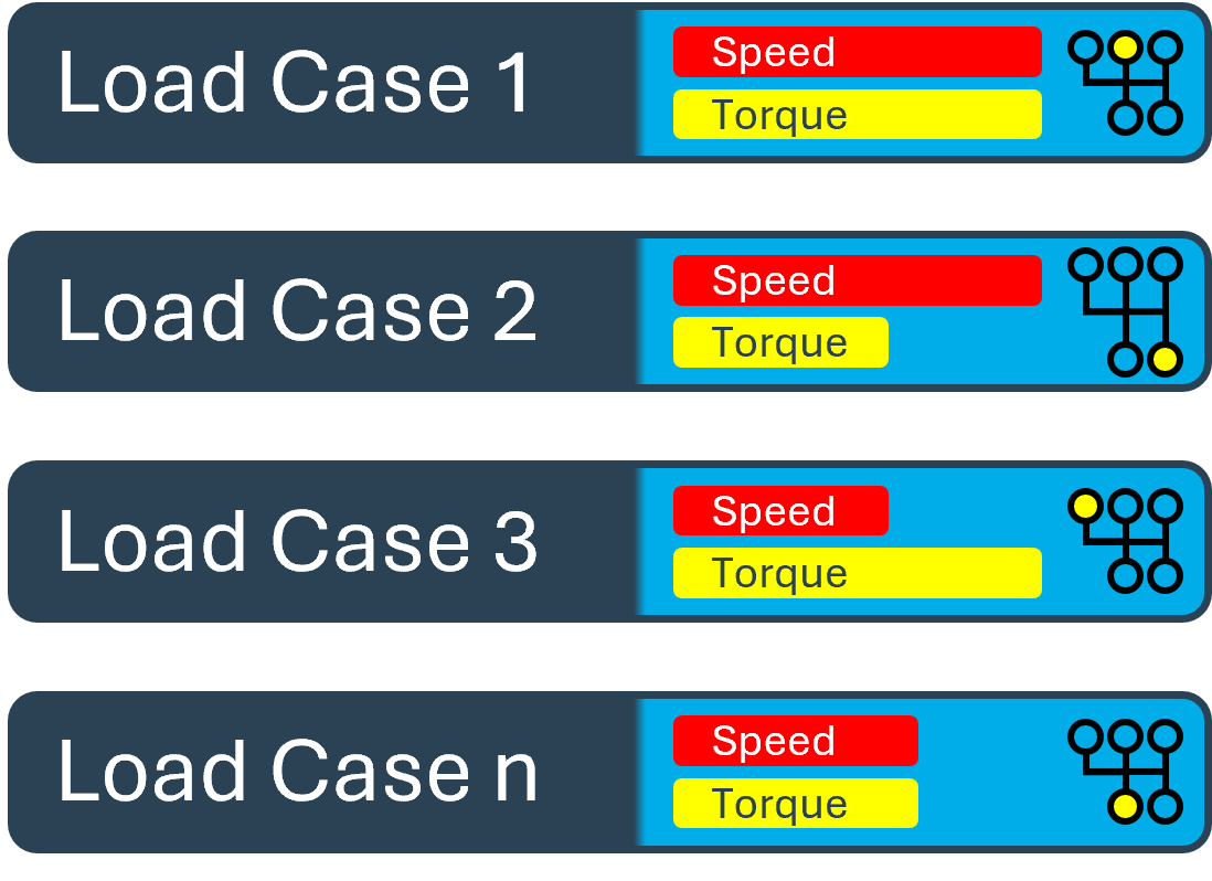 With this type of load spectrum, any combination of loads and selected gears can be specified, along with the associated time components. The time share, operating temperature, gear selection, power flow data, and external loads can be specified for each load case. |
Using load spectra in the overall system
"Consider load spectrum" must be checked in the Calculations tab of the Gear Unit to include a load spectrum as part of a system calculation.
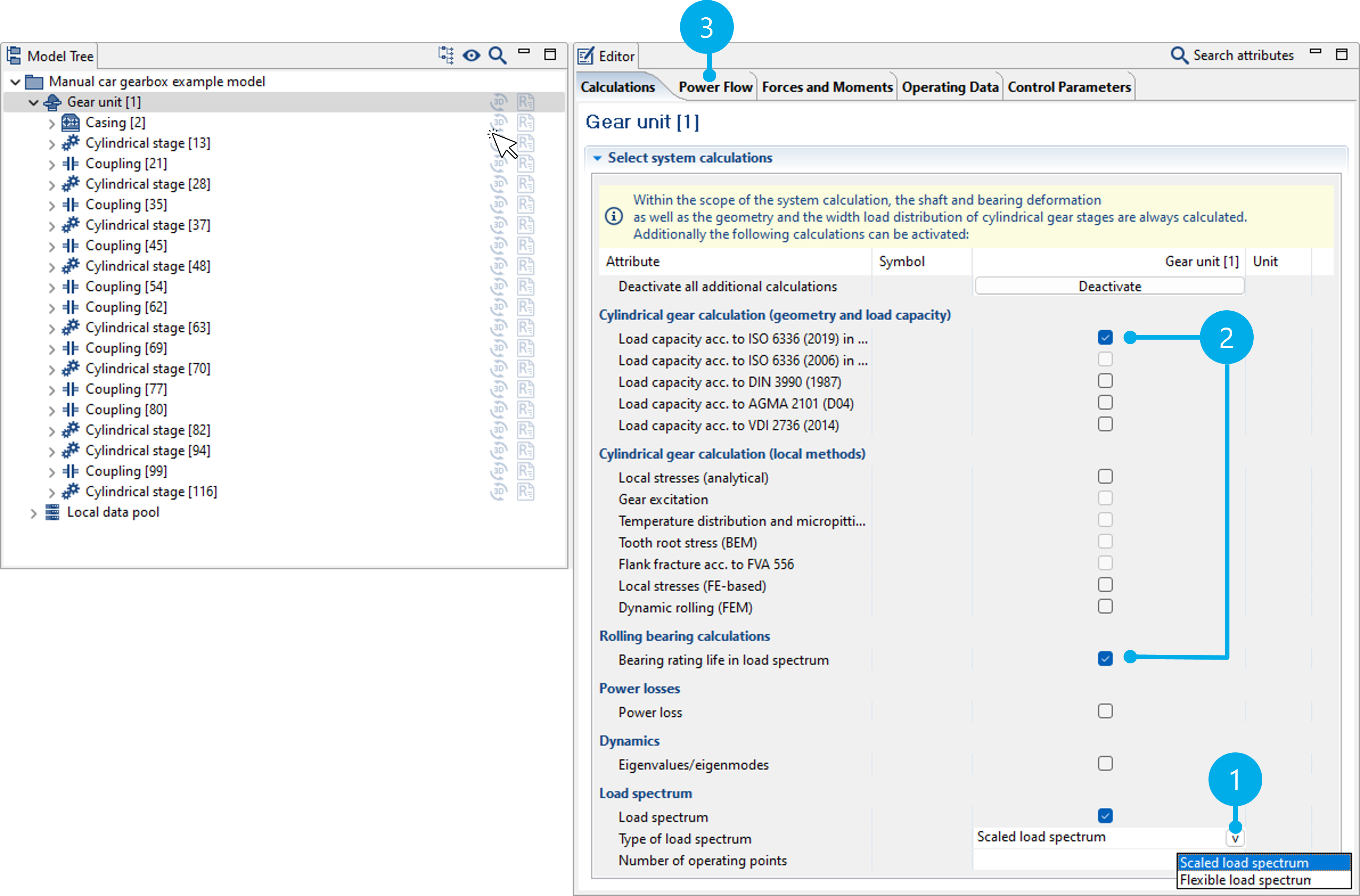
(1) Activates the load spectrum calculation as part of the system calculation. Scaled or flexible load spectra can be selected.
(3) Calculations in which the load spectrum is considered have "load spectrum" in their name.
(4) Load spectra and gear selections are specified in the "Power Flow" tab. The specifications vary according to the selected type of load spectrum calculation. They are described in the following.
Scaled load spectra
With scaled load spectra, load spectra can be specified as a percentage change to the load and speed as part of the system calculation. Load-time measurement series can be classified using the Global Database and then specified as a load spectrum. Alternatively, synthetic load spectra can also be created.
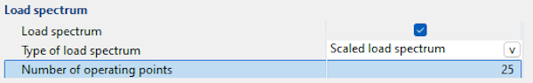
Number of points calculated in the load spectrum
The influences from the load (e.g., load distribution over the facewidth) and the speed (e.g., the lubricant film thickness) that apply to the load stages are considered as part of the load spectrum calculation.
In order to reduce the calculation time with large load spectra, the number of operating points for which the system is solved can be specified. These operating points are evenly distributed within the spectrum. The loads and the speeds are interpolated, and the corresponding damage percentages and lifetimes are calculated for all other steps of the load spectrum. If the number of load points is greater than or equal to the number of steps in the load spectrum, all steps are included in the system calculation.
Notice
When specifying only a speed spectrum, two different calculation options are available. If the torque is specified in the power flow defined for the gearbox, it is kept constant and only the speed is varied. If the power of the gearbox is specified, the torques in the load stages are adjusted so that the power remains constant.
Specifying load spectra and time shares
In the load spectrum calculation, an individual load spectrum can be specified for each gear in the gearbox. This can be configured in the Power Flow tab of the Gear Unit component.
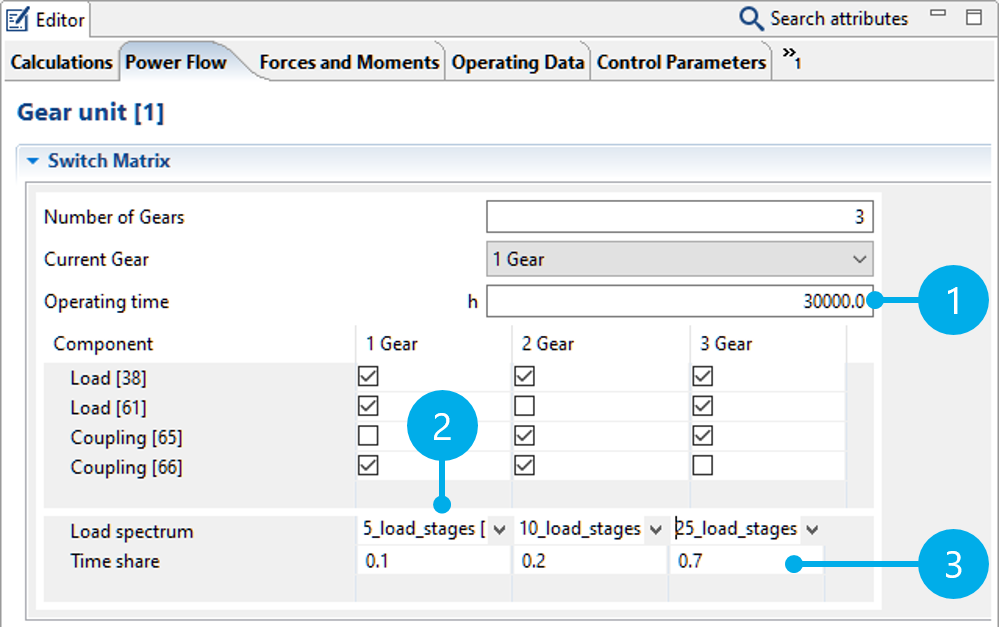
(1) Specification of the total service life of the gear unit.
(2) A load spectrum can be selected from the Global Database for each gear.
(3) Distribution of the total service life to the individual gears.
Time shares are used to distribute the specified total service life of the gearbox to the individual gears by specifying weighting factors. A time share is calculated from the weighting factor divided by the sum of all weighting factors multiplied by the total service life. The time shares can be entered as percentages, factors, or hours. The following entries lead to the same result:
Total number of hours: 30,000 | ||||
Gear | Factor | Factor | Percentage | Hours |
|---|---|---|---|---|
Gear 1 | 0.1 | 2 | 10 | 3000 |
Gear 2 | 0.2 | 4 | 20 | 6000 |
Gear 3 | 0.7 | 14 | 70 | 21000 |
If existing percentage or hourly weighting factors are used, the sum does not need to correspond to 100 % or the total number of hours. For example, if the specified total number of hours in the table above was 60,000 h instead of 30,000 h, the individual time shares would be internally converted to 6000 h (Gear 1), 12,000 h (Gear 2) and 42,000 h (Gear 3).
Creating load spectra
Load spectra are saved as data records in the Global Database. Load spectra saved in the database can then be added to any gearbox model as a database component.
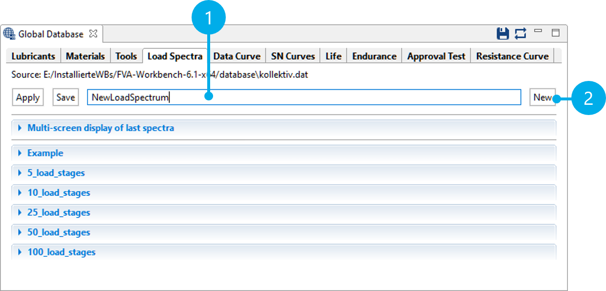
(1) Name of the new load spectrum
(2) Creates a new load spectrum data record.
Importing load spectra as .csv
Load spectra can be imported as .csv files (comma-separated values). These files can be created in Excel or another spreadsheet program. The step frequency must be specified in the first column. Load amplitudes can be specified for the torque and speed in the second and third columns. The load spectra can have one or two columns. An optional title for the data series can be specified in the first row.
Notice
Commas must be used as a decimal separator in the data series. The default decimal separator can be configured in Excel under file -> options -> advanced.
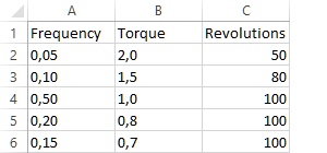
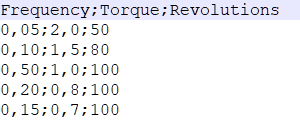
Load spectrum with 2 data series for torque (factor) and speed (%). The file is shown in Excel on the left and as a .csv file in the text editor on the right.
- Figure 11. Import the example file
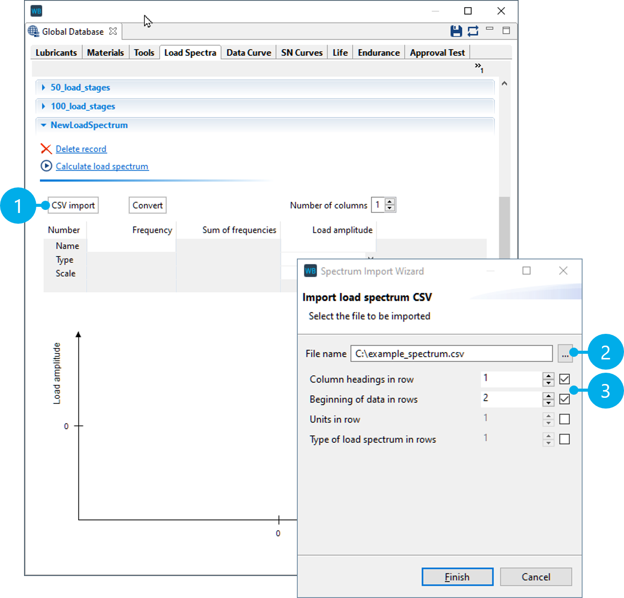
(1) Starts the .csv import
(2) Selects the file
(3) Selection of which row includes the title and where the data series starts.
- Figure 12. Specify the type and units of the data series
(1,2) After a successful import, the type must be specified for each data series (torque/speed), as well as whether the values are percentages (%) or factors (--).
(3) Once all information is complete, the data record can be saved in the Global Database.
Creating synthetic load spectra
Synthetic spectra can be useful in general investigations and preliminary design. They can be described mathematically using three parameters: spectrum scope H0, highest value Ŝa, and shape parameter ν. The larger the shape parameter ν, the greater the damage content of the synthetic load spectra with the same scope H0 and highest value Ŝa.
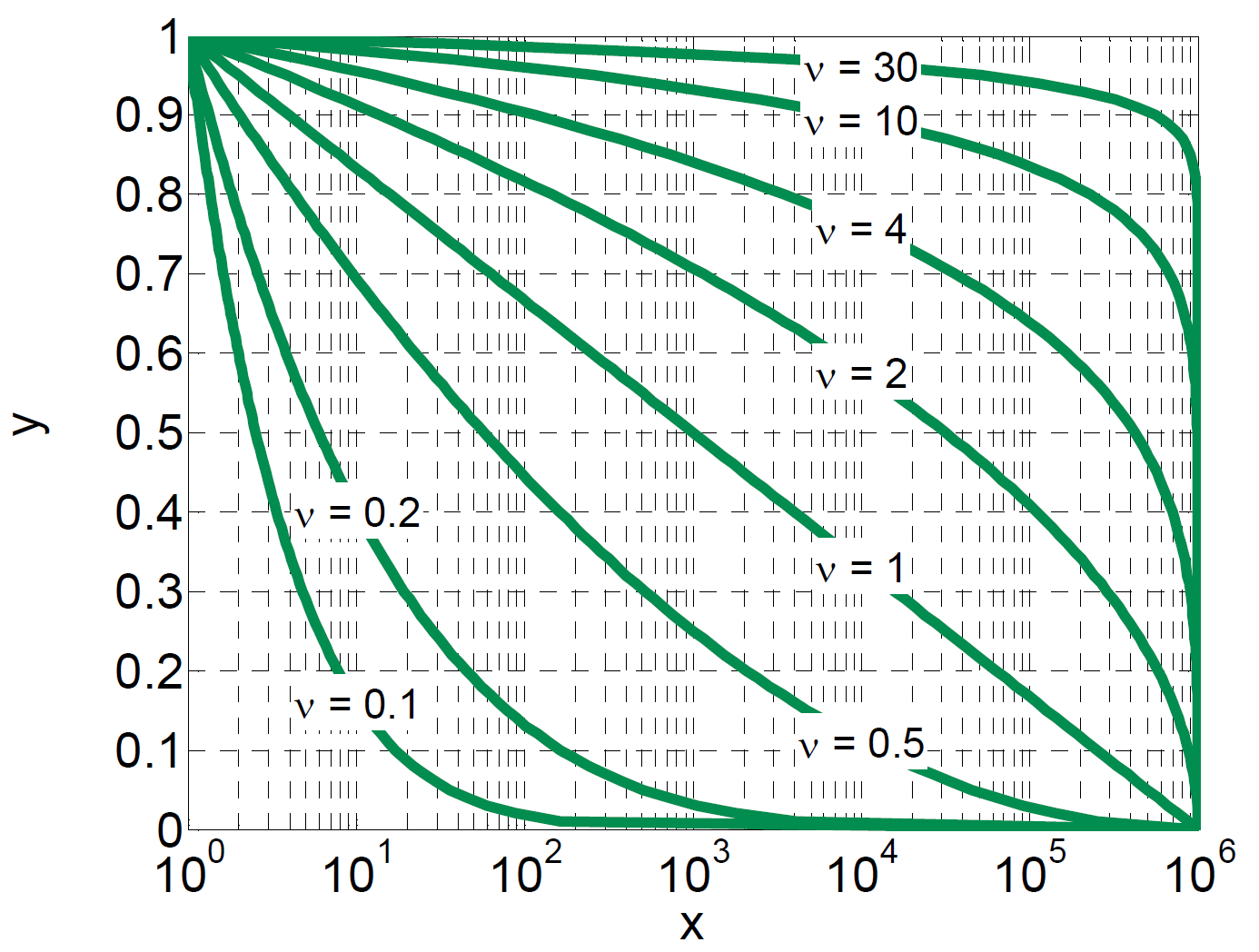
X axis: cumulative frequency H (log)
Y axis: amplitude, relative to the highest value of the spectrum
- Figure 14. Create a load spectrum
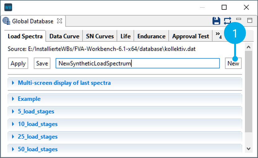
(1) Creates a new load spectrum
- Figure 15. Start the load spectrum calculation
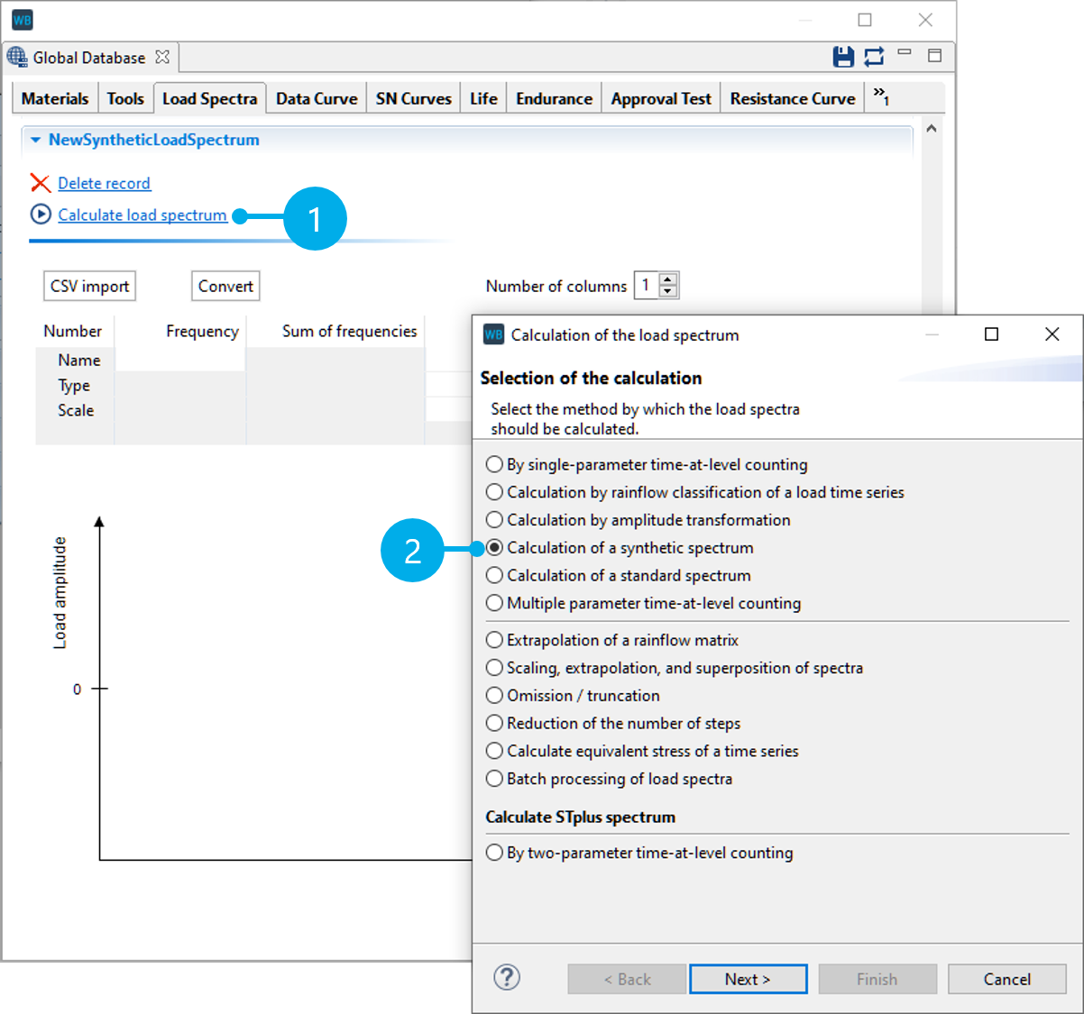
(1) Starts the load spectrum calculation
(2) Creates a synthetic load spectrum
- Figure 16. Specify the load spectrum parameters
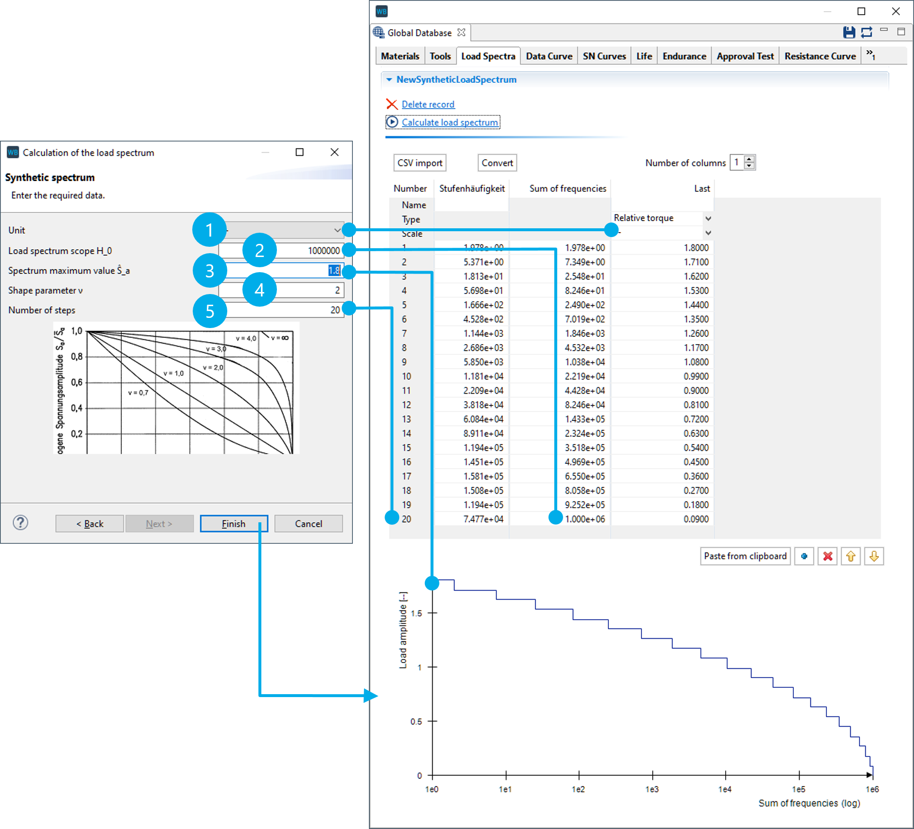
(1) Unit of the load amplitudes ("--" for factor)
(2) Number of load cycles
(3) Highest value of the spectrum (here, 1.8 x nominal torque)
(4) Shape parameter ν of the load spectrum
(5) Number of steps in the load spectrum
Flexible load spectra
With flexible load spectra, any combination of loads and selected gears can be calculated. The time share, operating temperature, gear selection, power flow data, and external loads can be specified for each load case. This makes it possible to consider auxiliary units that are not active in all operating states. Gearbox components with a variable transmission ratio and a specific efficiency curve can be integrated in the power flow using the generic "transmission ratio element" component.
A separate system calculation is performed for each load case, followed by an accumulation of the load cases with their respective time shares. This allows users to subsequently track the effects of the various individual operating states as well as the overall results of the calculation in the FVA-Workbench reporting,
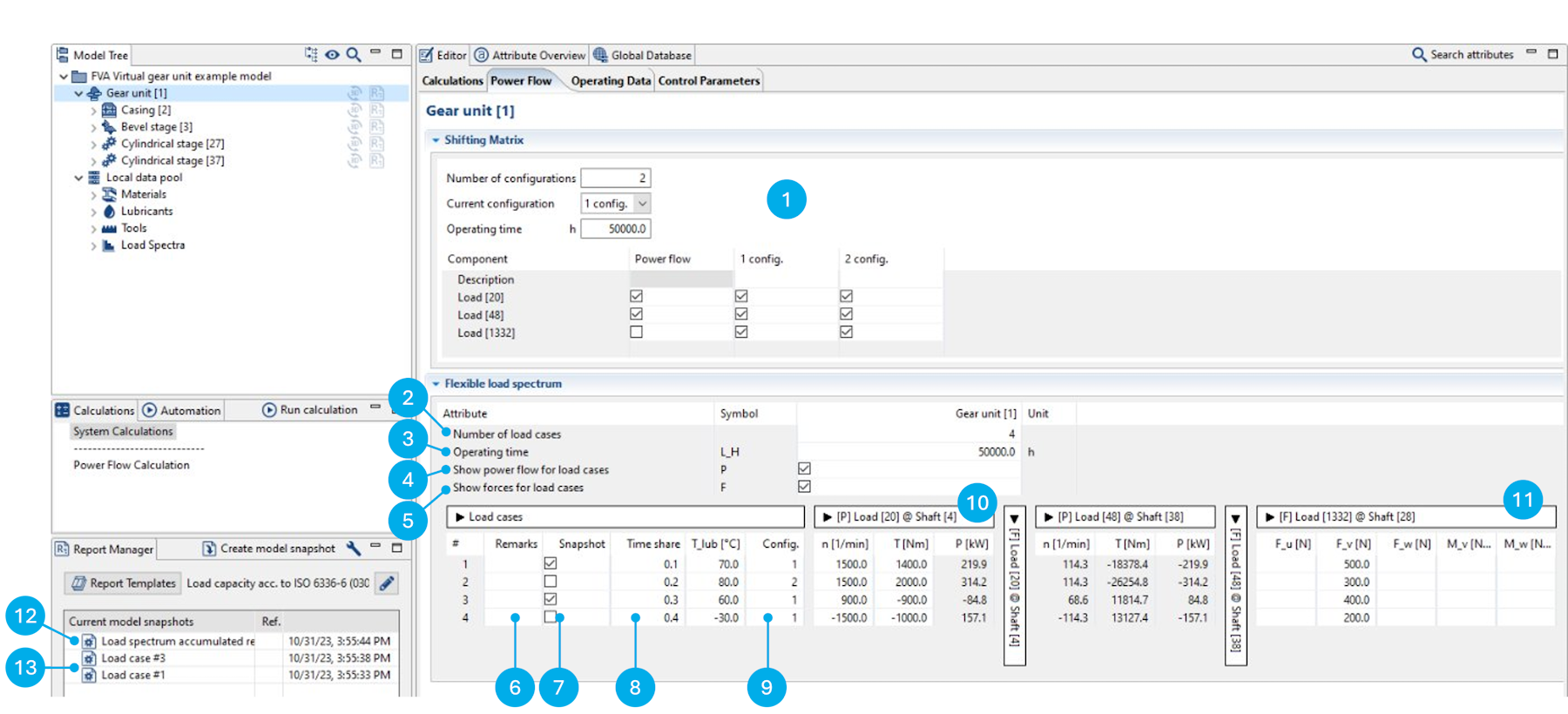
(1) | The switching matrix can be used to define different configurations for the power flow by activating and deactivating loads. |
(2) | Specification of the number of load cases, in which each load case represents a line in the table. |
(3) | Specification of the total operating time of the gearbox. This value is considered in all load capacity calculations for the entire system. |
(4) | Shows or hides the fields for the power flow data in the load case table. |
(5) | Shows or hides the fields for external loads in the load case table. |
(6) | A description can be entered for each load case. The labels in this column are also used for the names of the model snapshots -> (13). |
(7) | The checkboxes in this column determine whether a model snapshot should be created for this load case. The model snapshot contains the detailed calculation results for the load data specified in the load case. |
(8) | The distribution of the total operating time to the individual load cases can be specified in the "time share" column. |
(9) | Specification of which configuration from the switching matrix should be used for the load case. |
(10) | Specification of the speed, torque, and power for a load component in the gearbox. Only two of the three attributes need to be provided, the third value is calculated automatically. The values must be prefixed with a sign (+/-). |
(11) | Specification of external forces and torques for a load component in the gearbox. |
(12) | Model snapshot that contains the accumulated calculation results from the load spectrum. |
(13) | Model snapshots, which contain the detailed calculation results for a load case. All model snapshots can be restored as the base model. |
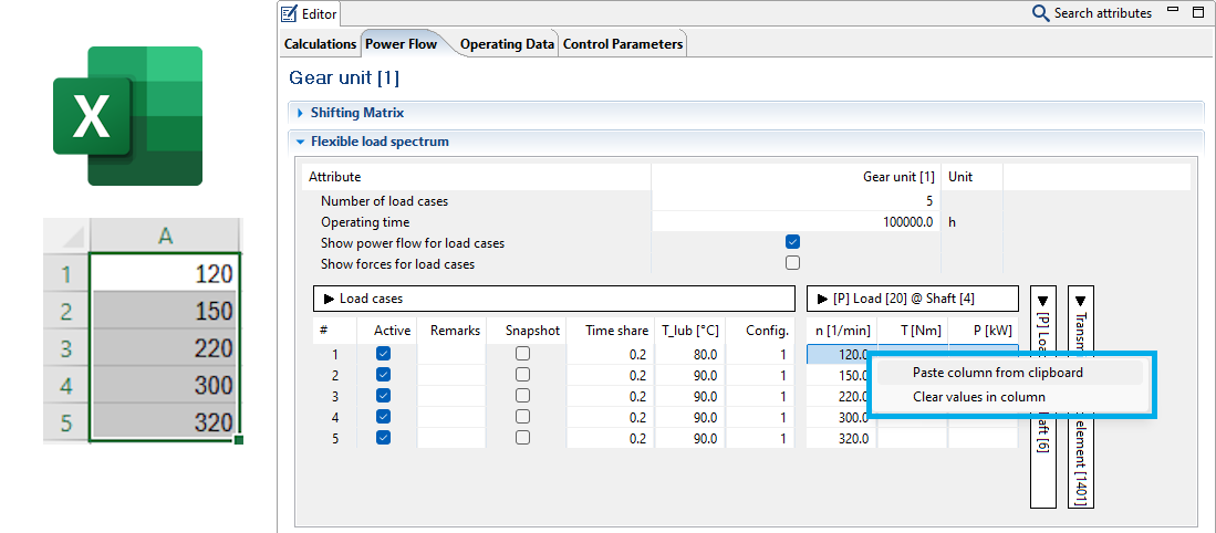
Values can be added by columns from Excel by right-clicking on a cell in the Editor.
Note
Cells may not be "selected" in the Editor before right-clicking.
Transmission ratio element components
Any two shafts can be coupled via the generic "transmission ratio element" component, and a transmission efficiency curve can be specified. A transmission ratio can be specified for each load case in the flexible load spectrum.
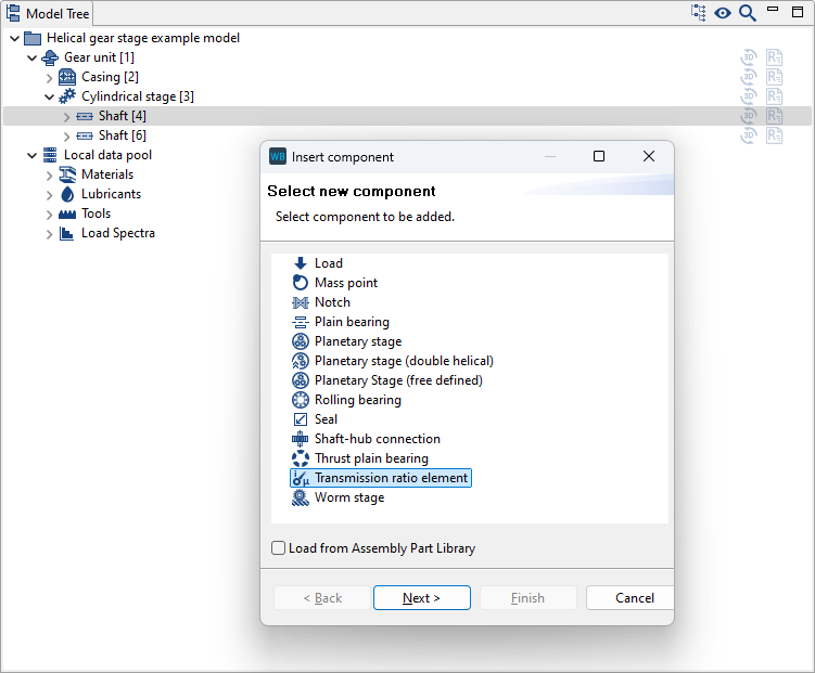
Transmission ratio elements can be added by right-clicking on a shaft in the Model Tree.
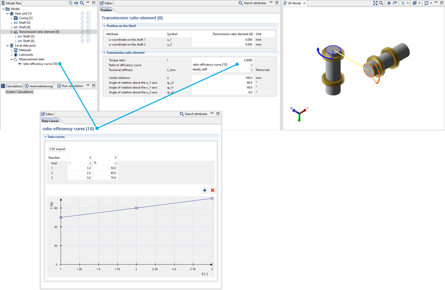
"Measurement data" records can be added via the Global Database. A transmission efficiency curve can be defined in this dataset. The dataset can then be assigned to a transmission ratio element.
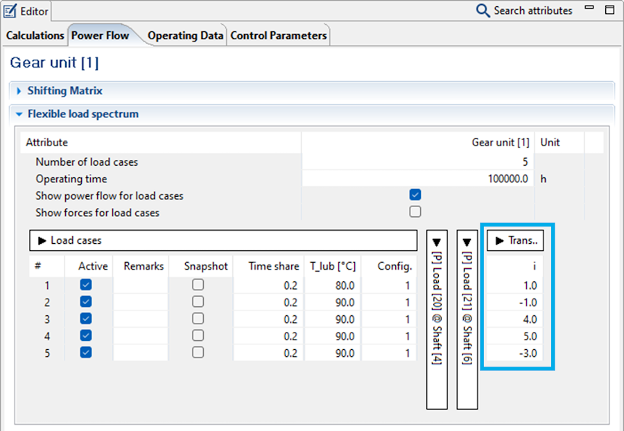
The transmission ratio of the "transmission ratio element" can be defined for each load case in the "Power Flow" tab. The associated efficiency is then determined from the characteristic curve.
Calculation options
Load spectra can be considered in the following calculations in the FVA-Workbench:
Cylindrical gears
Tooth flank & tooth root load carrying capacity acc. to ISO 6336 Part 6:
Safety factor (spectrum) acc. to Miner
Static safety
Continuous safety
Various damage accumulation hypotheses can be selected
Stress collectives and Woehler S-N curves
Maximum permissible scaled total number of load cycles
Gear excitation
Excitation level over the load
Tooth force level over the load
Force amplitudes over the load
Excitation amplitude level over the load
Transmission deviation amplitudes over the load
Maximum transmission deviation over the load
Mean transmission deviation over the load
Bevel gears
Standard bevel gear calculation (standard calculation acc. to ISO 10300 (2014))
Comparison of variants for local calculations
Mean specific gear tooth stiffness
Velocity level at 1000 U/min
Efficiency
Double amplitude of the total working variation
Minimum safety against scuffing
Maximum Hertzian contact stress
Maximum flash temperature
Maximum tooth root stress
Minimum safety against pitting of the pinion
Minimum safety against pitting of the gear
Local damage accumulation (tooth root/tooth flank damage sum)
Rolling bearings
Rolling bearing lifetime (accumulated lifetimes)
Shafts
Strength calculation acc. to FKM (2012)
Different damage accumulation hypotheses can be selected (Miner-elementary and Miner-consequent)
Conservative consideration of non-proportional stresses