Bevel gears - 3D neutral data
The 3D neutral data interface for discrete surface descriptions is an input interface for BECAL which includes the complete description of a gear set. It can be used for both bevel and hypoid sets (curved toothing, straight toothing, helical toothing) as well as beveloid and cylindrical gears.
This interface includes:
Basic geometry dimensions
Relative position of the gears (in simplified neutral data or simplified Standard.KGD)
Complete point description of the tooth (surface) geometry (3D neutral data)
Basic geometry and relative position
Both simplified neutral data that conforms to the Klingelnberg-defined interface and simplified Standard.KGD files can be used as inputs for the basic geometry. These files must contain the following information:
Number of teeth, normal module, pressure angle, helix angle, spiral direction
Face width, tooth depth, addendum modification, tooth thickness alteration coefficient
Tooth boundary
Reference, tip, and root cones
Distance between point of axial intersection and reference, tip, or root cone
Axial displacement, axial angle of intersection
The $ BERANDUNG input section contains the polyline of the flank edge. If this section is missing, the polyline is calculated in BECAL from the following values:
Root cone, tip cone, inside and outside supplementary cones
With consideration of the following, if available:
Conical rotation at the toe (width and angle of the tip easing) and
Cylindrical rotation at the heel (tip eased diameter)
All flank edges are uniformly described by a polyline; spherical tip boundaries can also be approximated with sufficient accuracy. Point 1 is always the toe root, Point 2 the heel root, and the following points run counter-clockwise along the tip edge toward the toe.

Examples of tooth boundaries
The polyline in the Standard.KGD must also meet the following requirements:
Consists of at least 4 points (for example, with theoretical tooth boundary)
The points are numbered in a counter-clockwise fashion (see illustration)
Point 1 describes the inner point on the root cone (toe)
Point 2 describes the outer point on the root circle (heel)
The following is an example of the $ BERANDUNG section of a Standard.KGD file. The first row is the number of boundary points for the respective gear. This is followed by the Z and R coordinates of the points. If the number of boundary points is different for the pinion and wheel, the percent sign (%) is used as a placeholder.
$ BERANDUNG
                  5                         4           Punktezahl
     60.59719     13.08327     21.71926     58.31119    Z, R( 1)
     85.73152     19.73649     28.37248     83.44552    Z, R( 2)
     83.67412     27.50888     20.60009     85.50292    Z, R( 3)
     62.65494     21.76898     13.94687     60.36859    Z, R( 4)
     58.53979     20.85566      %            %          Z, R( 5)
The $ MASCHINENEINSTELLUNGEN section contains the spiral direction of the paired gears. The following is specified for spur gears:
Pinion or Gear1: Spiral direction = 1
Ring gear or Gear2: Spiral direction = -1
The information contained in the $ UEBERSETZUNGEN and $ SCHNEIDENGEOMETRIE input sections is only relevant for load capacity calculations:
Rolling or shaping method, (1 … rolling method, 0 … shaping method)
Blade edge radius of the tool
If the gears were not manufactured using the rolling or shaping method, the $ UEBERSETZUNGEN and $ SCHNEIDENGEOMETRIE input sections are not included in the simplified Standard.KGD. If these input sections are missing, the data is calculated from the surface geometry.
The following example shows the Standard.kgd geometry input interface for a bevel gear when an additional surface description is provided in the form of a point cloud.
Example of a simplified Standard.KGD for a bevel gear:
Klingelnbergv.- Datensatz fuer BECAL (intern)
            Ritzel                      RAD
     konvex         konkav       konvex        konkav
$ GRUNDGEOMETRIE
                 35                        37           Zaehnezahl
            2.50001                   2.50001           mittl. Normalmodul
           10.00000                 -10.00000           mittl. Schraegungsw.
                         15.00000                       Achswinkel
                          0.00000                       Achsversatz
     20.00000     20.00000     20.00000     20.00000    Eingriffswinkel
            7.29047                   7.70953           Teilkegelwinkel
            7.29047                   7.70953           Kopfkegelwinkel
            7.29047                   7.70953           Fusskegelwinkel
            0.00000                   0.00000           Breite Kopfkuerz.
            0.00000                   0.00000           Kegelw. Kopfkuerz.
           95.32178                 100.24183           kopfgek. Durchmesser
          350.08059                 350.08059           mittl. Teilkegell.
           11.00000                  11.00000           Zahnbreite
            5.62502                   5.62502           Zahnhoehe
            0.02300                  -0.02341           Profilversch.-faktor
            0.02244                  -0.02956           Zahndickenaend.-faktor
            0.00000                   0.00000           Erzeugungsabstand
          -20.16188                 -18.19953           Kopfkegelabstand
           24.16467                  23.73100           Fusskegelabstand
$ BERANDUNG
                  4                         4           Punktezahl
    342.18399     40.68545    341.89297     43.07107    Z, R( 1)
    353.09506     42.08134    352.79351     44.54673    Z, R( 2)
    352.38126     47.66089    352.03891     50.12091    Z, R( 3)
    341.47018     46.26499    341.13836     48.64525    Z, R( 4)

$ MASCHINENEINSTELLUNGEN
                 -1                         1           Spiralrichtung
$ UEBERSETZUNGEN

            1            1            1            1    gewaelzt
$ SCHNEIDENGEOMETRIE


      0.75000      0.75000      0.75000      0.75000    Kopfradius (Messer)
The number of blank lines in these sections must be maintained to preserve backwards compatibility with older BECAL projects.
Description of the tooth surface using 3D neutral data files
The tooth surface is described via an ASCII file for each gear which includes points for the effective tooth flanks, the root areas, and the transition curves from the effective tooth flank to the root area for the left and right tooth flanks. Normal vectors are also included for all points of the effective tooth flank and the root area. The points of the surface description are located on a grid which covers the entire tooth surface. The location of the right and left flanks relative to one another is specified by the tooth thickness angle at a defined grid point on the effective tooth flank.
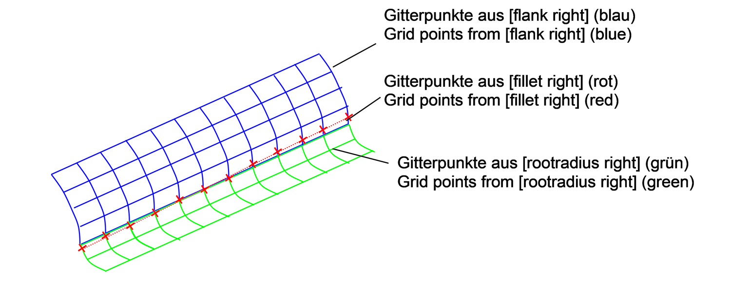
Schematic diagram of the point grid on a tooth flank
The flank grids of the ring gear and pinion are described in two separate files:
g_o___nm.dat
p_o___nm.dat
These ASCII files are structured as follows:
Division into chapters (the order of the chapters is arbitrary).
Required chapters:
[general]
[thickness]
[flank right], [flank left]
[rootradius right], [rootradius left]
[fillet right], [fillet left]
Data rows contained in the chapters:
Identifier with equal sign
String: includes data that is interpreted according to the identifier
Comment lines start with "comment"
Any number of blank lines is allowed between chapters
[general] chapter
The [general] chapter must contain the spiri parameter for the spiral direction:
Right-hand gear: spiri = 1
Left-hand gear: spiri = -1
The following is specified for spur gears:
Pinion or Gear1: spiri = 1
Ring gear or Gear2: spiri = -1
[general]

ident=FVA-G44 9/34
date_time=08.01.2014 09:51
spiri=    1.00
version=  4.20
[flank right] and [flank left] chapter
The [flank right] and [flank left] chapters contain the flank points of the left and right flanks in a specified grid. The size of the grid is specified by the number of columns and rows. This is followed by the flank points and the associated normal directions:
Identifier consisting of the column and row number of the grid point
Cylindrical coordinates: z, r, φ
Normal vectors: nz, nr, nφ
The following rules must be observed:
Equal column numbers in related chapters [flank right], [rootradius right] and [fillet right] or [flank left], [rootradius left] and [fillet left] always refer to the same profile section.
The number of columns in all of the above chapters must be identical.
All points must be specified within a profile line from the tooth tip to the root area.
Position of the work wheel in the coordinate system used:
Bevel and hypoid gears
The origin of the coordinate system O is the intersection of the axes in the gearbox.
The z-axis is the axis of the work wheel.
Spur gears and similar
The origin of the coordinate system OB is determined from the tooth reference plane. (The tooth reference plane can be selected anywhere between the toe and the heel of the gear.)
The z-axis is the axis of the work wheel.
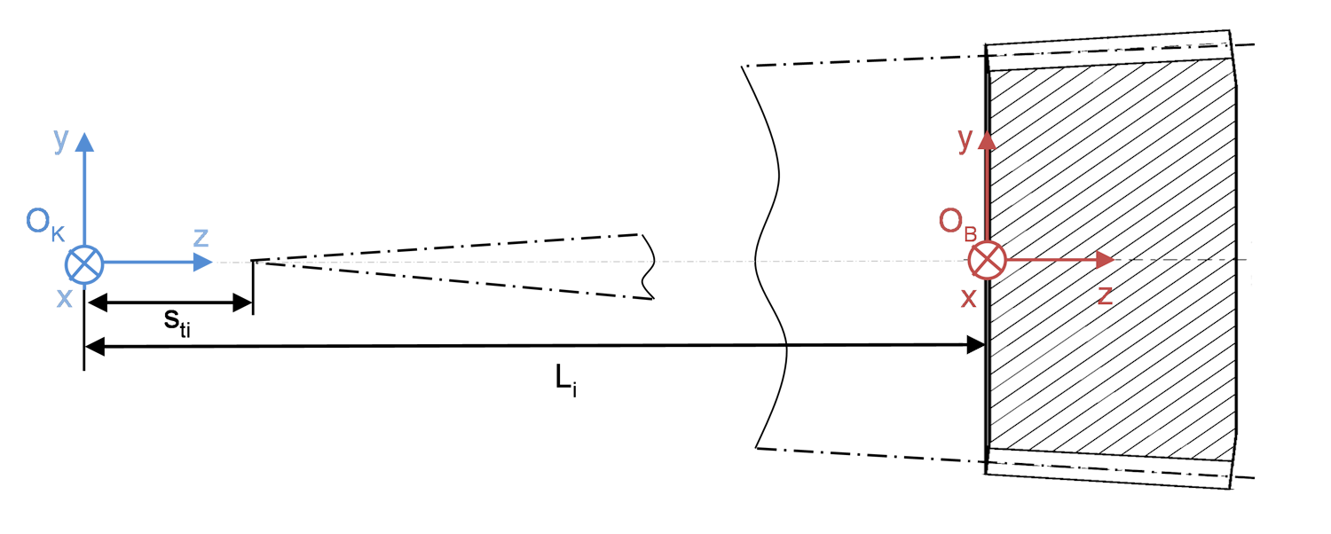
Definition of the coordinate systems
OK - BECAL reference system for crown wheel and pinion with origin OK
OB - Reference system for beveloid gears with origin OB
Li - Mounting dimension for beveloid gears (distance from point of axial intersection to tooth reference plane)
Sti - Distance from the tip of the reference cone to the point of axial intersection

Coordinate systems for the flank points and the normal direction
A flank point P is described in the coordinate system Σ = {O,ex,ey,ez} by the cylindrical coordinates (z,r,φ), where x = r⋅cos(φ) and y = r⋅sin(φ).
The standardized normal vector n at point P is described by by the cartesian components (nz,nr,nφ) of the local coordinate system ΣP = {P,ez,er,eφ} induced by P. The coordinate origin is P, the r-axis has the opposite direction to the perpendicular of P on the work wheel axis, and the z-axis has the same direction as the z-axis of Σ.
[flank right]
rows=   25
lines=  25
comment=        z_Soll           r_Soll        phi_Soll         nz            nr           nphi
00010001=    18.3880000000    64.7530394595 -0.0595882557 -0.3937065159  0.1901845697  0.8993469902
00010002=    18.6779000000    64.5568929891 -0.0570050932 -0.3878902292  0.1884217968  0.9022407642
00010003=    18.9679000000    64.3608306367 -0.0544587507 -0.3819185961  0.1865541169  0.9051716674
…
00250023=    39.3319000000    81.9767629800  0.0839853787 -0.5096971406 -0.1858177377  0.8400479708
00250024=    39.6219000000    81.7806623130  0.0855858112 -0.5046029116 -0.1901057366  0.8421613329
00250025=    39.9119000000    81.5845056276  0.0871859053 -0.5266101610 -0.1686012393  0.8332198752

[flank left]
rows=   25
lines=  25
comment=        z_Soll           r_Soll        phi_Soll         nz            nr           nphi
00010001=    18.3880000000    64.7530216553 -0.0121095564 -0.2655996122  0.2192825219 -0.9388141571
00010002=    18.6779000000    64.5568827169 -0.0140620255 -0.2581884992  0.2164994854 -0.9415235906
00010003=    18.9679000000    64.3607638461 -0.0159694937 -0.2505079387  0.2134200523 -0.9442974393
…
00250023=    39.3319000000    81.9767402478  0.0565447308  0.0685990146  0.5032808953 -0.8613956789
00250024=    39.6219000000    81.7806508442  0.0553727221  0.0306014161  0.5212085856 -0.8528805096
00250025=    39.9119000000    81.5845039505  0.0537539454 -0.0695967680  0.5665488334 -0.8210838625
[rootradius right] and [rootradius left] chapters
The [rootradius right] and [rootradius left] chapters are structured similar to the [flank right] and [flank left] chapters. They include the coordinates of the points in the root area which are directly below the flank grid and extend to the base of the root. The lower points of the flank grid ([flank right], [flank left]) correspond to the upper points of the root grid ([rootradius right], [rootradius left]).
[rootradius right]
rows=   25
lines=  16
comment=        z_Soll           r_Soll        phi_Soll         nz            nr           nphi
00010001=    25.3472000000    60.0468271017 -0.0082515842 -0.4188050885  0.2538255398  0.8718800910
00010002=    25.5034000000    59.9413076728 -0.0062931150 -0.4825105936  0.3040692159  0.8214167267
00010003=    25.6595000000    59.8356658848 -0.0038076775 -0.5616918864  0.3667291423  0.7416279127
…
00250014=    40.6366000000    81.0944484441  0.1001255091 -0.8360539389  0.5486470910 -0.0004251905
00250015=    40.6366000000    81.0944484441  0.1001255091 -0.8360539389  0.5486470910 -0.0004251905
00250016=    40.6366000000    81.0944484441  0.1001255091 -0.8360539389  0.5486470910 -0.0004251905

[rootradius left]
rows=   25
lines=  20
comment=        z_Soll           r_Soll        phi_Soll         nz            nr           nphi
00010001=    25.3472000000    60.0468765393 -0.0458068163 -0.3092965065  0.2688403657 -0.9121735190
00010002=    25.5034000000    59.9412645563 -0.0473803553 -0.3779973956  0.3159945468 -0.8702099835
00010003=    25.6595000000    59.8357119493 -0.0494170089 -0.4670979308  0.3759012714 -0.8003235328
…
00250018=    40.5994000000    81.1195876114  0.0372308276 -0.8380637168  0.5455718500  0.0007503694
00250019=    40.5994000000    81.1195876114  0.0372308276 -0.8380637168  0.5455718500  0.0007503694
00250020=    40.5994000000    81.1195876114  0.0372308276 -0.8380637168  0.5455718500  0.0007503694
[fillet right] and [fillet left] chapters
The [fillet right] and [fillet left] chapters contain the coordinates of points on the transition curve between the effective flank area and the root area. The grid points of [fillet right] and [fillet left] always consist of only one row per column; i.e., one point per profile line.
[fillet right]
rows=   25
lines=   1
comment=        z_Soll           r_Soll        phi_Soll     C1
00010001=    24.6093000000    60.5458592627 -0.0139532297   1
00020001=    25.2526000000    61.4186122921 -0.0128413294   1
00030001=    25.8953000000    62.2917652536 -0.0114043934   1
…
00230001=    38.5728000000    79.8744507890  0.0730783730   1
00240001=    39.1949000000    80.7616145545  0.0797452457   1
00250001=    39.8154000000    81.6497803217  0.0866355460   1

[fillet left]
rows=   25
lines=   1
comment=        z_Soll           r_Soll        phi_Soll     C1
00010001=    24.2372000000    60.7975060883 -0.0404091737   1
00020001=    24.8859000000    61.6666062371 -0.0395321415   1
00030001=    25.5338000000    62.5362687433 -0.0383274054   1
…
00230001=    38.2185000000    80.1140680842  0.0426661262   1
00240001=    38.8395000000    81.0019320881  0.0492446183   1
00250001=    39.4590000000    81.8907507418  0.0560572452   1