FVA-Workbench 11.0
FVA-Workbench 11.0
Important
A new licensing process is being introduced with the release of FVA-Workbench 11.0. Existing licenses must be reissued in order to use version 11.0.
This new module can be used to incorporate so-called Rotating Rainflow matrices and synthesize pseudo-stress-time histories at local evaluation points. In contrast to using standard load cases, this method also makes it possible to consider cycles resulting from shifting operations and the resulting stresses in the damage accumulation. For more information, see Rotating Rainflow Calculation.
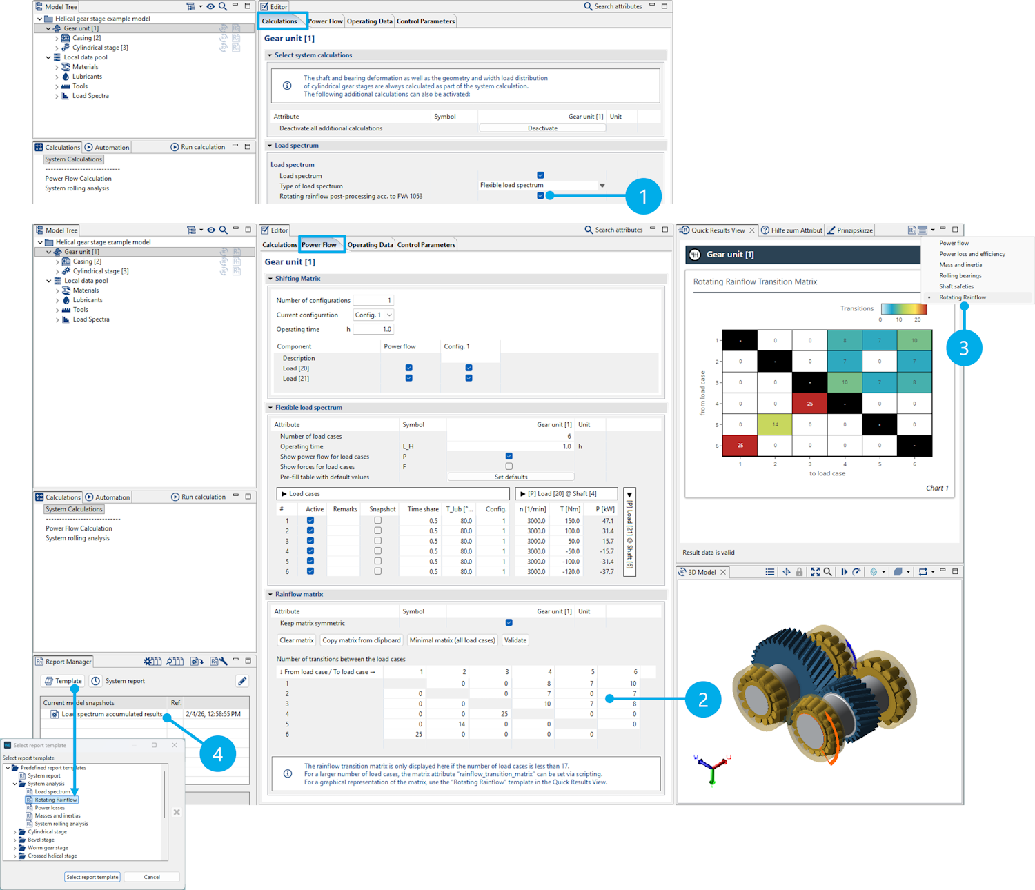
(1) Under the "Calculations" tab, the Rotating Rainflow calculation can be activated as an additional calculation to the flexible load spectrum calculation.
(2) A transition matrix, specifying transition frequencies between the individual load cases in the Rotating Rainflow matrix, must be entered for the calculation.
(3) The transition matrix can also be displayed in the Quick Results View for quick visual inspection. This is especially helpful for large matrices.
(4) The Rotating Rainflow calculation is performed as part of the system calculation. The results are saved in a model snapshot which only contains the results of the load spectrum calculation. A report template is available for evaluating the results.
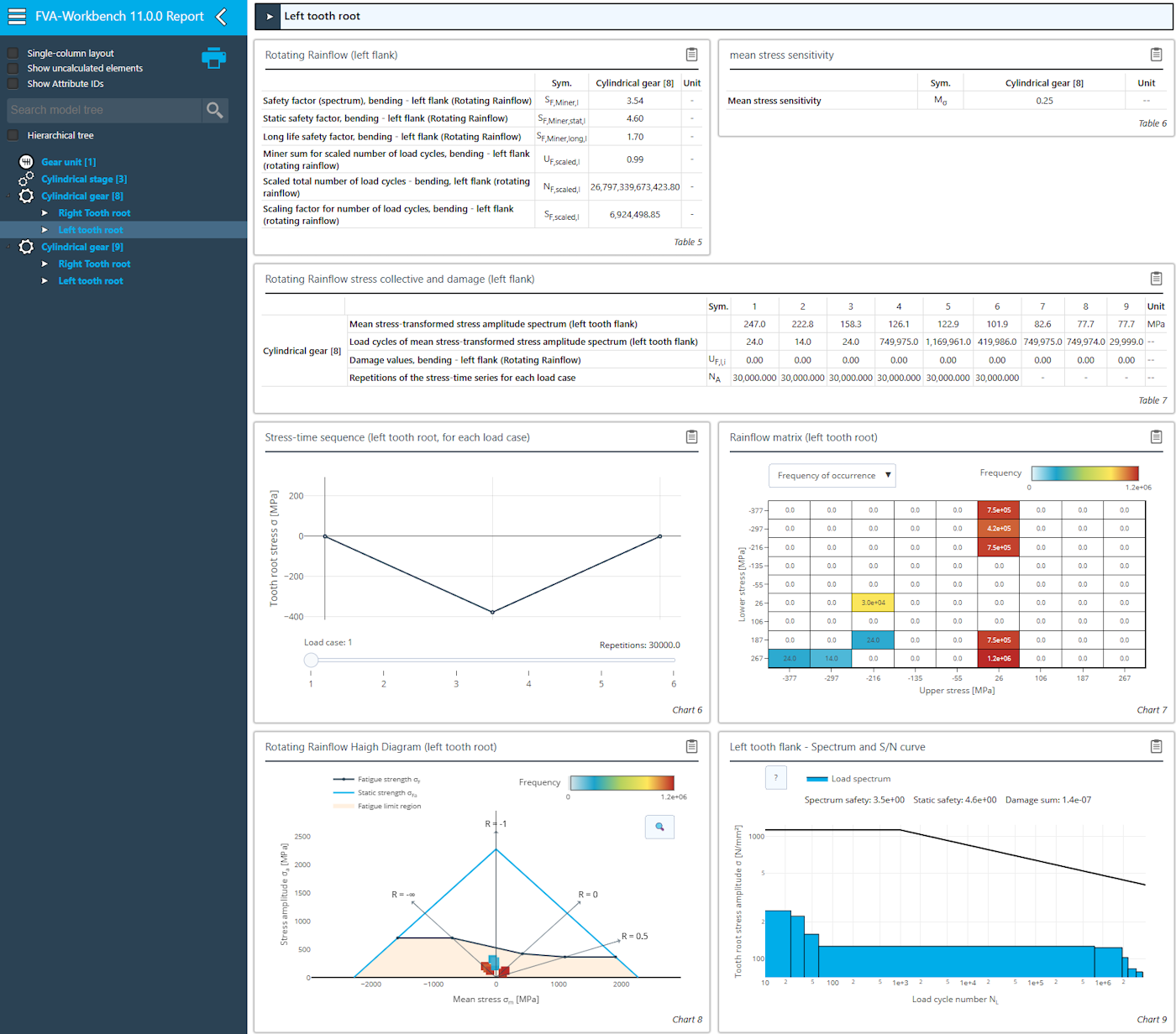
Output report for the Rotating Rainflow calculation
Skiving is a high-performance continuous generating process for internal and external gear teeth. The kinematics are based on crossed helical gears. The tool and workpiece are tilted by a crossed-axis angle and rolled together. To do so, the manufacturing processes for cylindrical gear profile generation have been expanded to include the new "skiving cutter" tool type. Flank and root standard load capacities as well as a 3D contact analysis can be calculated based on gear geometries generated by skiving.
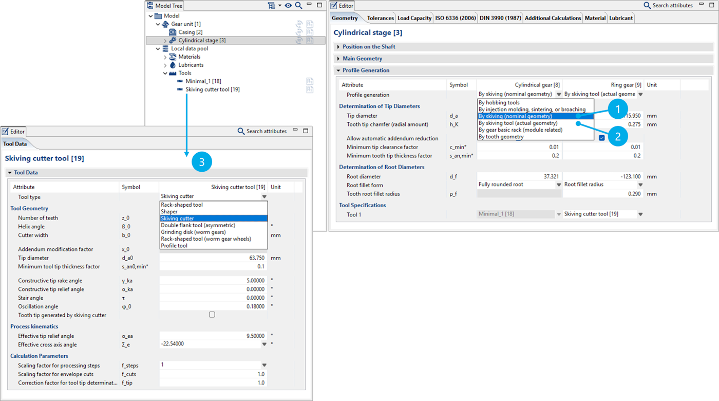
(1) The nominal profile of a skived gear is determined by specifying the tip and root circles as well as the root radius.
(2) The actual profile is determined by the manufacturing kinematics of the skiving process. Manufacturing deviations arise from the differences between the nominal and actual profiles. These differences can be considered in the local load distribution calculation.
(3) The data used to determine the actual profile is defined in the new "skiving cutter" tool type.
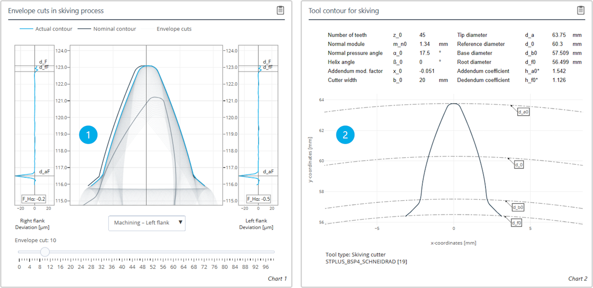
(1) The envelope cuts of the manufacturing process as well as the resulting contour are displayed. The deviations on the involute and in the tooth root area are shown for both the left and right flanks.
(2) Representation of the skiving cutter profile resulting from the user specifications.
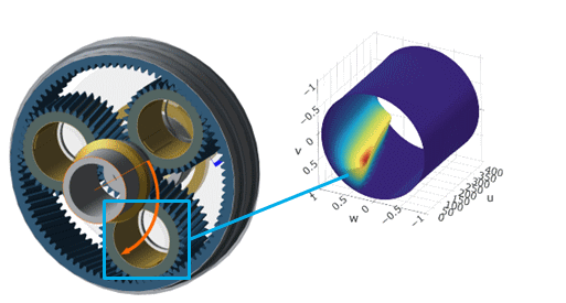
A universal contact friction model has been developed in collaboration with the Chair of Machine Elements, Gears and Tribology (MEGT) at RPTU as part of the FVA 998 research project series. It is now available in the FVA-Workbench for the following rolling bearing types:
Cylindrical roller bearings
Tapered roller bearings
Needle roller bearings
Ball bearings
This gives FVA-Workbench users access to a high-quality, physics-based, locally resolved contact friction model that enables more accurate predictions of rolling bearing load-dependent power losses. It also provides deeper insights into contact conditions and potential damage mechanisms. The universal friction model will also be available for different bearing types as well as gears in future releases.
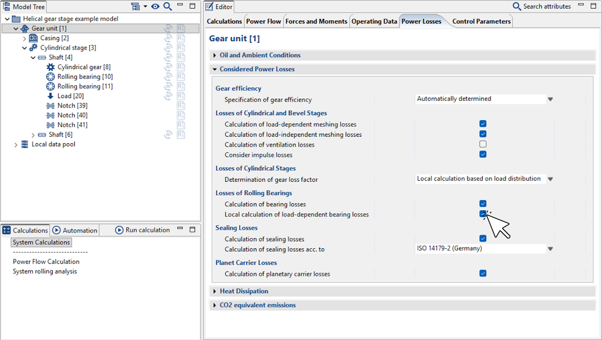
The calculation can be activated as part of the overall system calculation with "local calculation of load-dependent bearing losses."
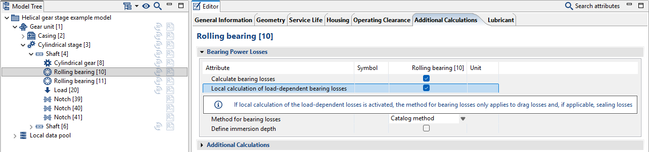
The calculation can also be enabled as an additional post-processing step for the bearing life calculation.
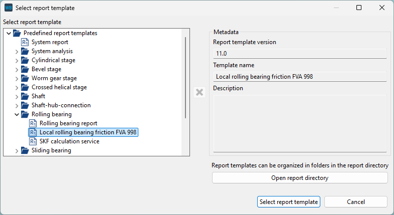
A new report template is available for evaluating the results.
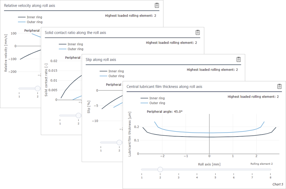
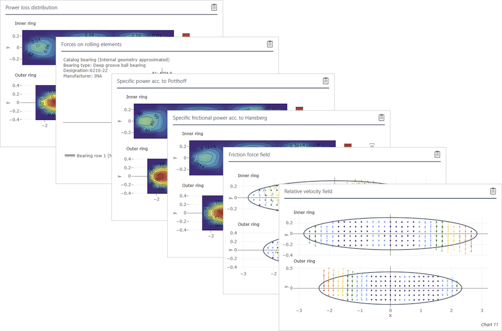
Results along the rolling axis for all rolling elements (left)
Results of the most heavily loaded rolling element (right)
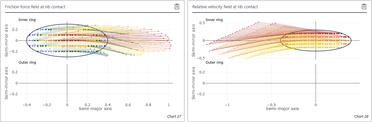
Locally resolved roller-rib contact in a tapered roller bearing
New options for specifying loss torque
A new power loss component has been added to FVA-Workbench. This can be added to a shaft and allows users to specify a freely defined loss torque. For example, this makes it possible to consider the losses of pumps or similar components.
It can also be specified through a characteristic map that relates rotational speed and lubricant viscosity to loss torque. The characteristic map is defined via scripting. An example script can be found in the attribute help.
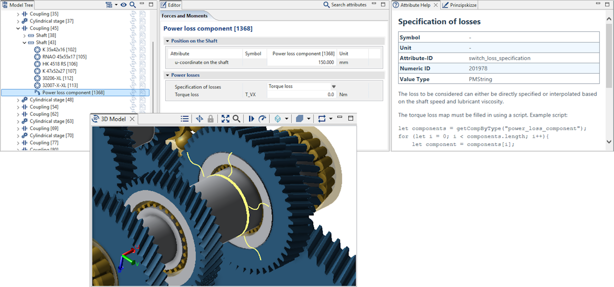
New torque loss component with the option to switch between a fixed torque loss and a characteristic map.
The existing coupling component has been extended to include an option for adding torque loss (or a loss torque map). Additionally, torque loss maps can now be specified for seals.
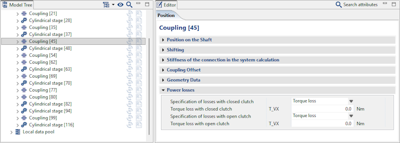
Torque loss can now also be specified for couplings and seals.
Consideration of the internal gear factor according to FVA 584 II
To better capture the specific meshing conditions of internal gears in the calculation of load-dependent gear losses using a contact-averaged approach (e.g., coefficient of friction acc. to Schlenk or Doleschl), FVA 584 II ("Friction of internal gears and heat management of planetary gears") proposes the consideration of an internal gear factor XIV. This factor describes the geometric influence when transitioning from a profile-equivalent external gear under equivalent operating conditions to a corresponding internal gear.
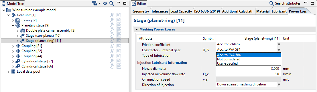
The internal gear factor XIV can either be:
calculated automatically
specified by the user
or neglected (XIV = 1)
Bugfixes and Additional Changes
An error in the consideration of the load-independent losses of sun and ring gears in planetary stages has been corrected.
An error in the consideration of planet carrier churning losses has been corrected.
An error in the system calculation with consideration of losses with "fixed" planetary stages has been corrected.
An error in the consideration of FE wheel bodies in the overall system calculation with consideration of losses has been corrected.
Changes/enhancements
The modification matrix diagram has been enhanced. The matrix values can now be displayed so that 0 corresponds to the smallest modification value on the flank.
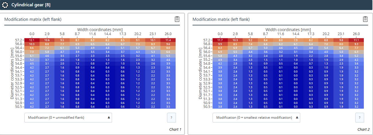
Left: 0 = unmodified flank; right (new): 0 = smallest modification value on the flank
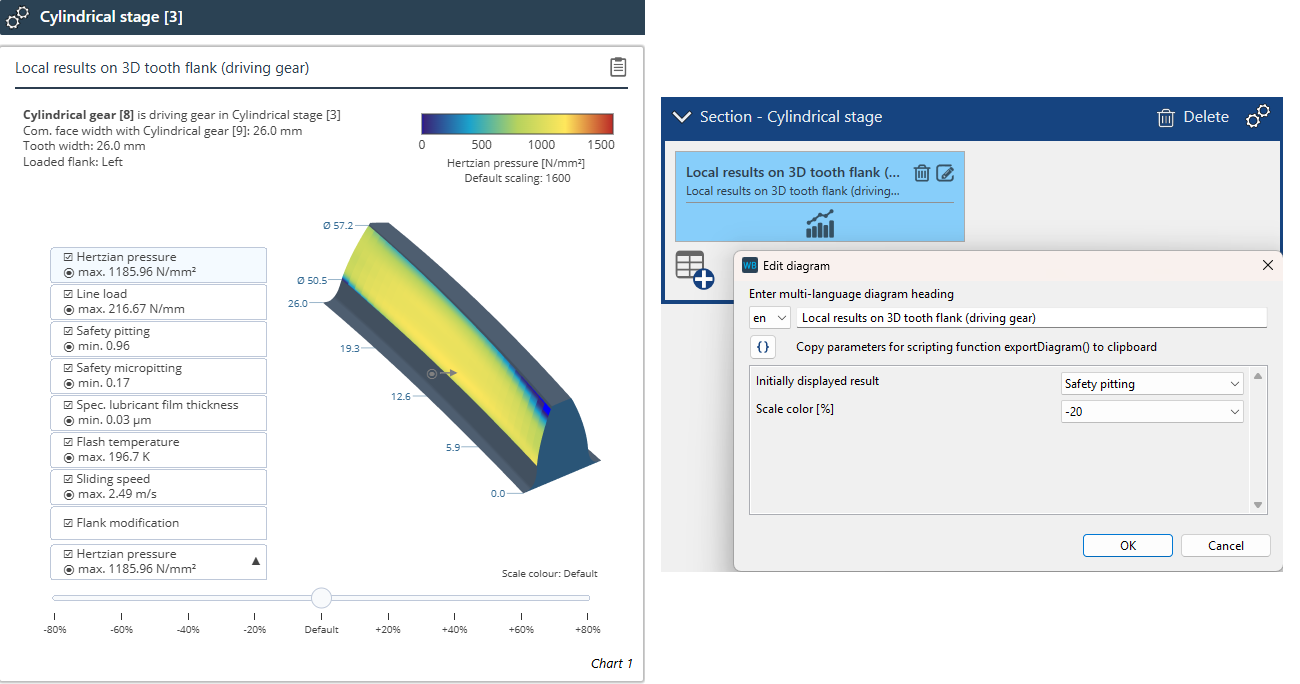
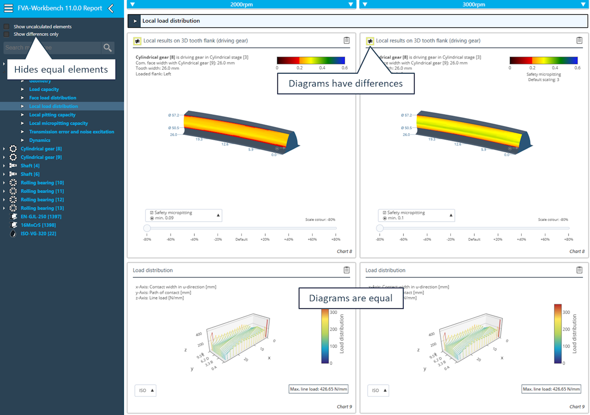
The diagram for displaying the local results on the 3D tooth flank has been revised. The maximum value for each result is now shown both as a number in the drop-down menu and as an arrow on the flank. In addition, the default result to be displayed and the color scaling can be set in the Report Configurator.
Bugfixes
If the face load factors KHβ or KFβ were user-specified for the LRS load capacity calculation, an error message incorrectly indicated that the value was not available. This has been fixed.
Values greater than 0.7 can now be specified for the alternating load factor YM
A bug in the display of the ring gear geometry with user-defined gear geometry has been fixed. In some cases, an excessively large tooth clearance was shown in the meshing diagram, even though the tooth clearance was calculated correctly.
The local pitting safety calculation is no longer performed when using a load spectrum because the required factors for the nominal load are not available from the ISO calculation. A corresponding error message has been added.
The SKF Bearing Catalog has been updated (as of 16.03.2026).
The NSK Bearing Catalog has been updated and enhanced (as of 03-2026)
New bearing types: Self-aligning ball bearings, thrust ball bearings, cylindrical roller thrust bearings, double-row cylindrical roller bearings, double-row tapered roller bearings
The Schaeffler Bearing Catalog has been updated.
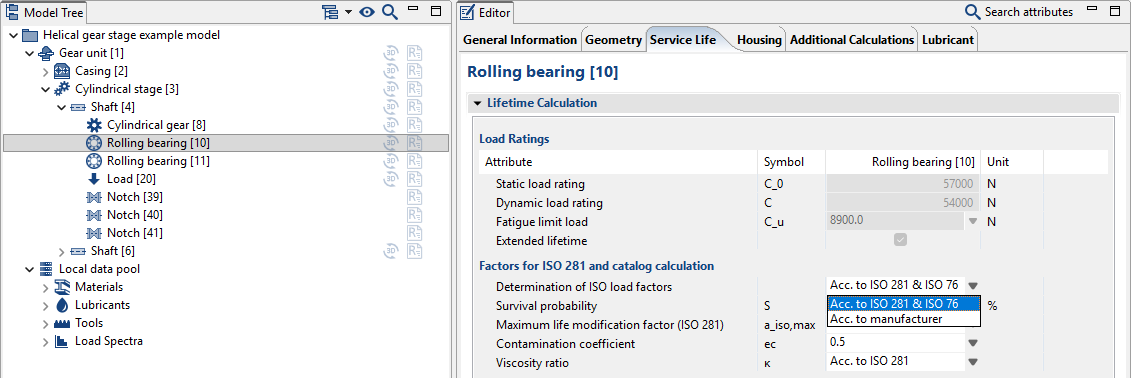
Enhanced calculation of load factors according to ISO 281. It is now possible to consider catalog factors from XML files for manufacturers other than SKF and Schaeffler. A switch has been added to toggle between "Load factors according to ISO 281" and "Load factors according to manufacturer specifications."
The thermally permissible rotational speed according to Schaeffler has been adjusted.
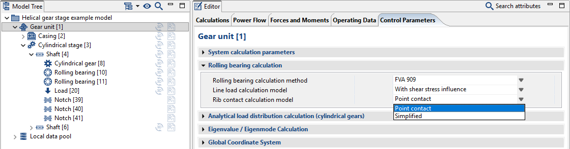
In addition to the simplified approach according to FVA 364, the rib contact of rolling bearings can now also be considered as a Hertzian point contact.
When importing REXS files, it is now verified whether the specified catalog identifier exists in the rolling bearing catalog. If this is the case, the imported data will be adjusted or overwritten accordingly. If the catalog entry is not found, the bearing will no longer be discarded, but instead is imported as a rolling bearing with the type "rolling bearing geometry" using the data included in the REXS data.
New calculation objective
The existing geometry design according to ISO 23509 has been split into two calculation objectives:
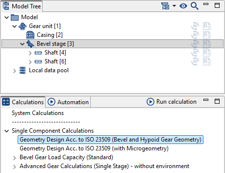
Geometry design according to ISO 23509 (gear geometry) In cases where local calculations are not required or when fast variant analysis is needed, the "Geometry design according to ISO 23509 (gear geometry)" can be used for individual stages, enabling the dimensioning of bevel and hypoid gear stages. All load capacity calculations according to standards or classification societies can subsequently be performed.
Geometry design according to ISO 23509 (with microgeometry)
The previous calculation objective has been renamed "Geometry design according to ISO 23509 (with microgeometry)"
New version of KNplus
The KNplus 5.2 calculation kernel has been integrated, which includes various bugfixes and functional enhancements.
Key changes and improvements
Bugfixes in ISO 10300:2014 (Method B2) and load spectrum calculations
Corrections and additions to REXS output
Scuffing load capacity calculation (ISO/TS 10300-20:2021, FVA 519 I)
Variable running-in factor (XE) can be defined
Calibration factor C1 can be configured for the coefficient of friction calculation
Alternative calculation of gear power loss according to FVA 821 (Method B instead of ISO Method C)
Optional consideration of the driving direction of the path of contact (deviation from standard)
Classification societies (DNV 2003, DNV/GL 2015)
Enhanced reporting (including subsurface fatigue, tooth root geometry, bending lever arm)
New geometry outputs
The following additional geometry parameters are now calculated for bevel gear geometry design in accordance with ISO 23509 and load capacity calculation in accordance with ISO 10300 (2023):
Inner and outer tip cone diameters and root cone diameters
Inner and outer helix angles
Extension of the ISO 23509 geometry calculation for straight bevel gears
Edge optimization enables the automatic adjustment of tooth edges to the mating gear contour.
The size of the point cloud can now be adjusted via a scaling factor.
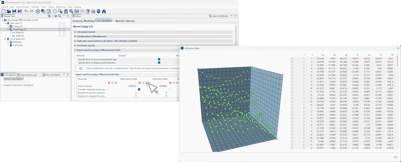
Import of bevel gear measurement data
The assistant for importing bevel gear measurement data has been revised.
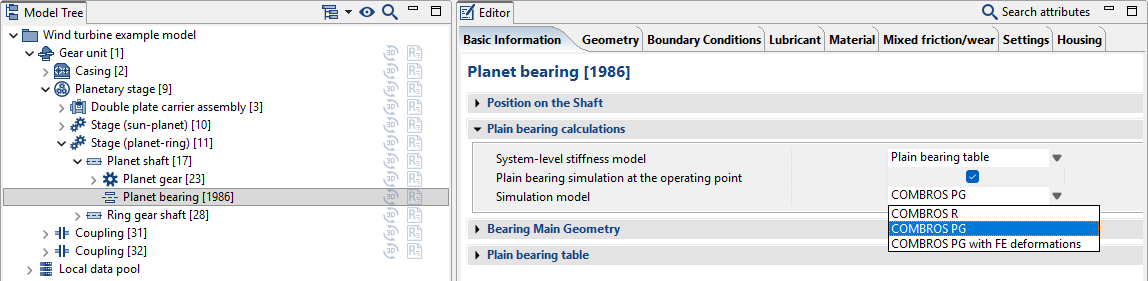
Planetary gear plain bearing calculations
The new COMBROS PG calculation module is focused on planetary gear plain bearings, especially for wind turbine applications. The calculation model includes a stationary pin with the oil supply on the inner side and the rotating planetary gear on the outer side. COMBROS PG is based on an efficient thermo-elasto-hydrodynamic calculation approach that has been theoretically and experimentally validated by the TU Clausthal Institute of Tribology and Energy Conversion Machinery. The COMBROS PG-FEM calculation variant uses corresponding FE structures to consider the elastic deformation of planet pins and planetary gears.
Plain bearing coordinate system
The coordinate system for plain bearings has been standardized. Parameterization is now independent of the direction of rotation. Diagrams are also now displayed in the FVA-Workbench coordinate system so that the results can be transferred directly to the model.
Output diagrams now use the FVA-Workbench coordinate system.
Additional changes
The plain bearing tables according to FVA 961 have been expanded. Tilting pad bearings with profiling >= 1.25 are now supported.
A new EasyEntry example model, "wind turbine gearbox with planetary bearings," has been added.
The handling of the standard load capacity calculation has been updated. As this calculation inherently involves losses, it is now only considered in system-level calculations when the power loss calculation is activated. In individual calculations, the standard load capacity is handled such that the nominal output torque at the worm wheel is specified. The input torque at the worm is increased accordingly to account for losses in order to achieve the specified output torque.
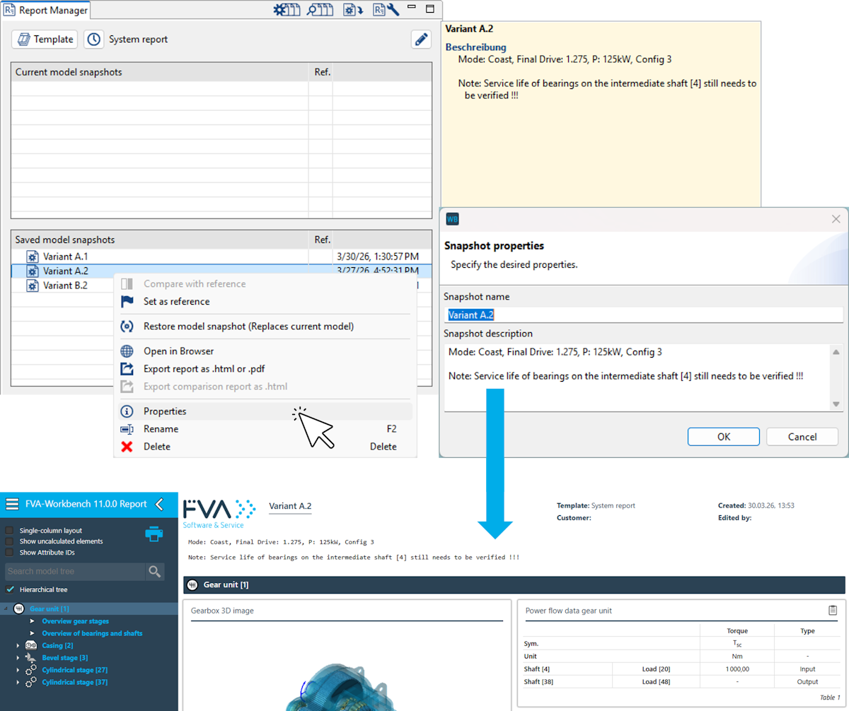
Display Snapshot Description in the Report
The description entered for a snapshot is now shown below the header in the output report.
Important
When a new snapshot is created, this field is empty, so no description is displayed in the report. For existing models with saved snapshots, the description is prefilled with the snapshot title by default and may need to be adjusted or cleared.
The description text of a snapshot can now also be set via scripting. In addition, the generateReport() function has been extended with options for setting the title and description.
Recently used report templates
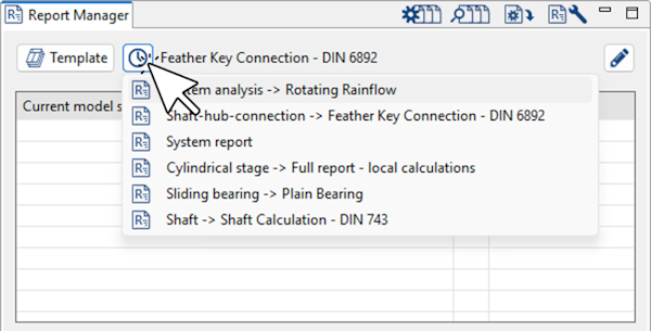
Recently used report templates can now be selected in the Report Manager
Imperial units in report tables
Metric and imperial units can now be selected for displaying the values of results in report tables.
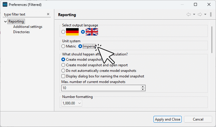
Output can now be toggled between metric and imperial units in the report settings.
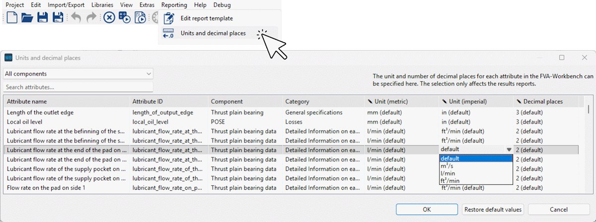
Metric and imperial units can be defined for each attribute in the "units and decimal places" dialog box.
User-defined matrix diagram
A new user-defined diagram is now available for representing matrix attributes. A new matrix attribute with the prefix custom_attribute_matrix_ has been added for this purpose. Support points in the X and Y directions can be defined using array attributes.
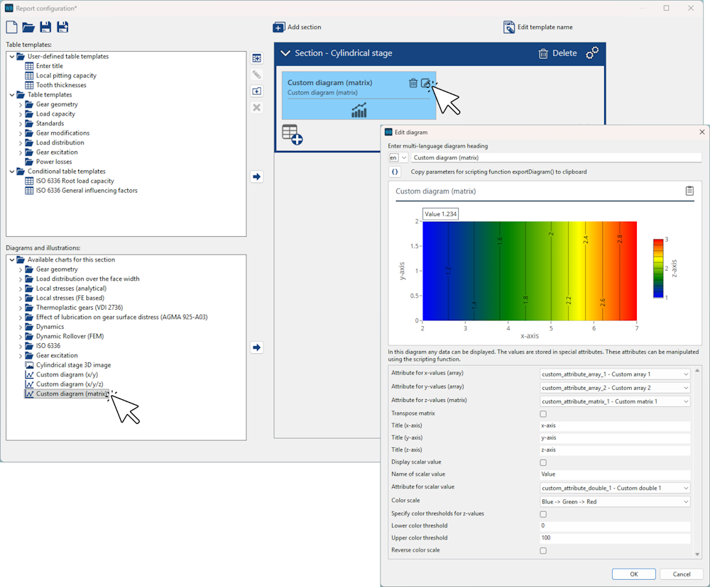
The diagram can be added and configured for various component types in the Report Configurator. The data is populated via scripting.
Example script for populating the diagram:
let compID = 3;
let matrix = [[5,10], [5,10], [5,10], [5,10]];
let x_array = [1,2,3,4];
let y_array = [1,2];
let value = 1.234;

setAttr("custom_attribute_double_1", compID, value,   RDAT);
setAttr("custom_attribute_array_1",  compID, x_array, RDAT);
setAttr("custom_attribute_array_1",  compID, y_array, RDAT);
setAttr("custom_attribute_matrix_1", compID, matrix,  RDAT);
Campbell diagram for standalone shafts
Previously, the Campbell diagram was only displayed for shafts connected via gear stages. It can now also be displayed for shafts without gears, such as shafts connected with the rest of the model via couplings. The new diagram is available in the Report Configurator under the "shafts" section, and has also been included in the system report.
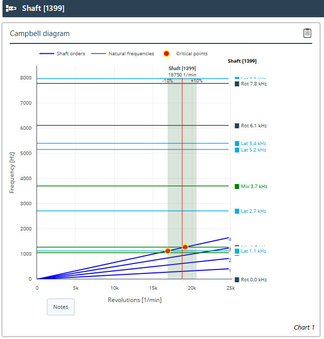
The new Campbell diagram is only displayed for shafts that are not connected via gear stages.
Additional changes
3D images of machine elements are now generated in parallel. This greatly accelerates report creation.
Values and tables that do not differ between two model snapshots can be hidden in comparison reports. This is now also possible for diagrams with no differences.
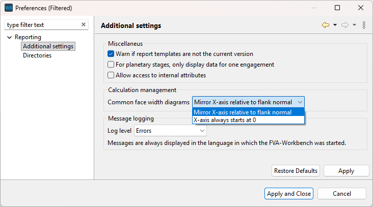
The x-axis mirroring in diagrams over the common facewidth feature introduced in FVA-Workbench 10.1 can now be turned on or off in the reporting settings.
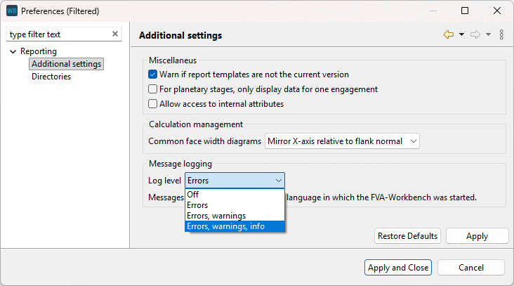
The log level for calculation messages output in the report can now be configured. This makes it possible, for example, to only show errors and warnings, but not information messages.
The behavior of the Model Tree in reports has been improved. When a node is selected, parent nodes are no longer automatically expanded - they now remain collapsed.
The position of multiple shafts can now be moved simultaneously.
Multiple shafts can be selected and moved using CTRL + click or via a selection rectangle.
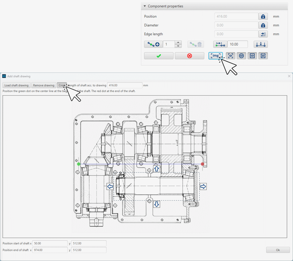
In the 2D Modeler, schematics can be used as background images for tracing the shaft geometry. These images can be cropped to a defined area. This makes it possible to use a schematic of the entire gearbox and individually crop it for each shaft in the 2D Modeler
Previously, background images could only be displayed while modifying the shaft contour. They can now also be displayed in the standard component view.
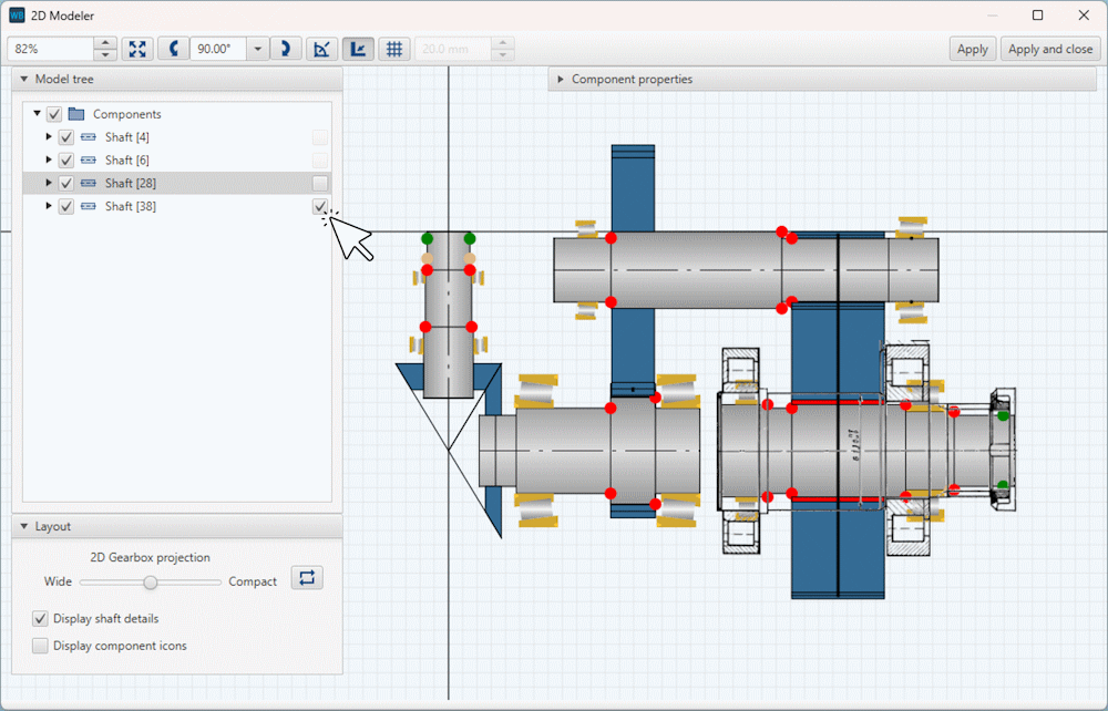
Background images can be individually shown or hidden for each shaft using the checkboxes of the Model Tree in the 2D Modeler.
Previously, couplings in planetary stages between pins and side plates or between web shafts and side plates were not displayed in the 2D Modeler. This caused issues with the positioning of couplings, particularly when using FE planet carriers. These couplings are now displayed in the 2D Modeler, like all other couplings, and can be edited there.
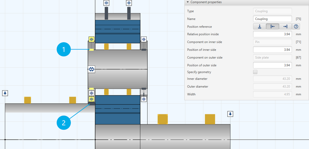
(1) Coupling between pin and side plate
(2) Coupling between web shaft and side plate
The gearbox layout in the 2D Modeler is now saved during an FVA-Workbench session. As long as no significant changes are made to the components, the layout is maintained when the 2D Modeler is reopened.
The configured grid size, snap mode, and rotation angle are now permanently saved.
The center of a shaft section is now also considered as a snap point in the "snap to edges" snap mode.
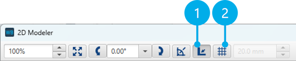
(1) "Snap to edges" snap mode
(2) "Snap to grid" snap mode
An error in the calculation of the position of couplings between pins and side plates of planetary gears has been corrected.
Section planes
Section planes have been revised and can now be used directly via the toolbar in the 3D Model.
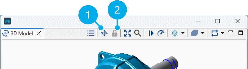
(1) Activates the section plane and allows it to be moved and rotated.
(2) Locks the section plane in its current position and allows you to continue working in the model as usual.
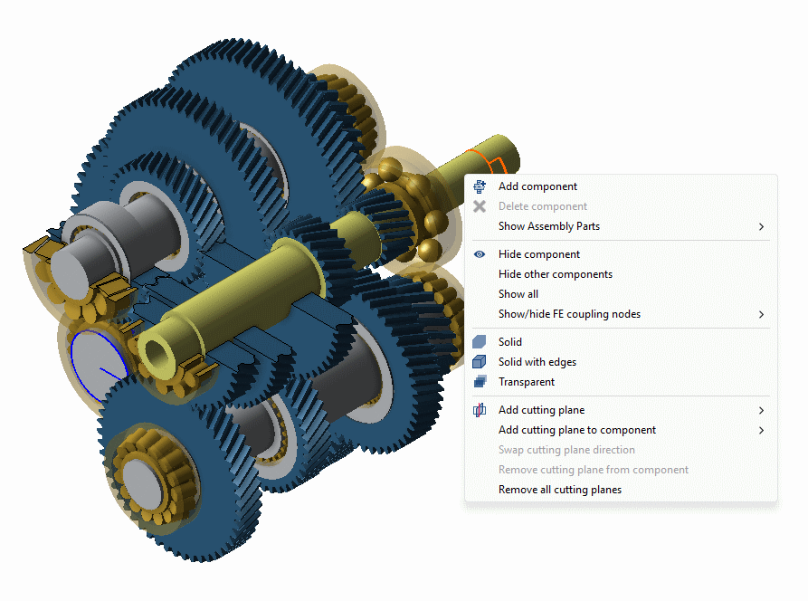
3D Model right-click menu
The 3D Model right-click menu has been revised and simplified. The following changes have been made:
For cutting planes, it is now possible to select the stage whose angle should be used for the cutting plane.
Cross-sections through individual components now function the same way as cutting planes.
The options for displaying FE coupling nodes have been moved to a submenu. FE reduction nodes can now also be displayed.
The assembly part library options have been moved to a submenu.
Component transparency
The setting to display a component as transparent is now saved in the Model Snapshot. When a Model Snapshot is restored, the transparency of components is also restored accordingly.
With the new exportDiagram() function, reporting diagrams can now be exported as image files (.png or .svg) via scripting.
Here, the exportDiagram() function was used to export the transmission error diagram after each step of a variational calculation. The individual images were then combined into a GIF animation using the ezgif tool.
The number of planetary gears in a planetary stage can now be set via scripting using the setNumberOfPlanets() function.
The getAttr() function has been extended so that attributes of instance components, which are actually only defined for the associated parent component, can now also be queried. In the FVA-Workbench, only values that apply to the individual instance are stored on instance components. The new logic first checks whether the desired attribute is present on the instance component. If this is not the case, the associated parent component is automatically queried. Example: It was previously not possible to read the number of teeth of a planetary gear directly from a concrete instance of a planet (e.g., Planet @ 120°), but only from the parent component. This is now possible.
The readFileAsString() function has been extended with a parameter to specify the encoding of the file to be read.
The runCalcMethod() function has been extended so that when the "createResultpath" option is activated, the calculation kernel files are also written to the specified directory in the event of an error or termination. This makes it easier to investigate failed or terminated calculations.
A new scripting function, sleep(), is now available. It pauses the execution of a script for a specified duration in milliseconds.
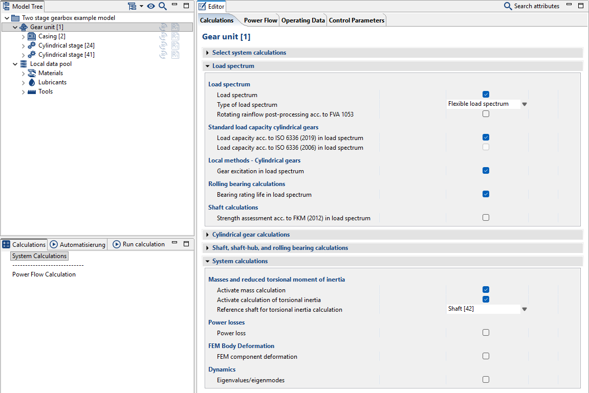
Selecting system-level calculations
The presentation of additional calculations for system-level calculations has been updated. All calculations which include a load spectrum are now grouped together in a single section. Calculations which are exclusively related to the system level are shown in a separate section. This section now includes a switch to enable mass calculations. This switch was previously enabled by default; however, it is now deactivated by default as it can increase computation time.
Converting bearing types
Rolling bearings can now be converted to axial or radial plain bearings, and vice versa, via the right-click menu in the Model Tree.
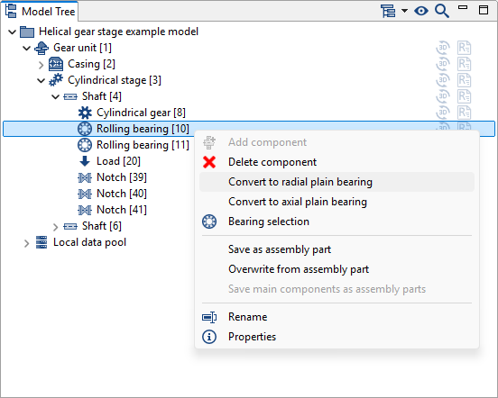
You can now change a bearing's type by right-clicking it in the Model Tree.
Sort components by type in the Model Tree

The Model Tree now includes a switch to group components by type.
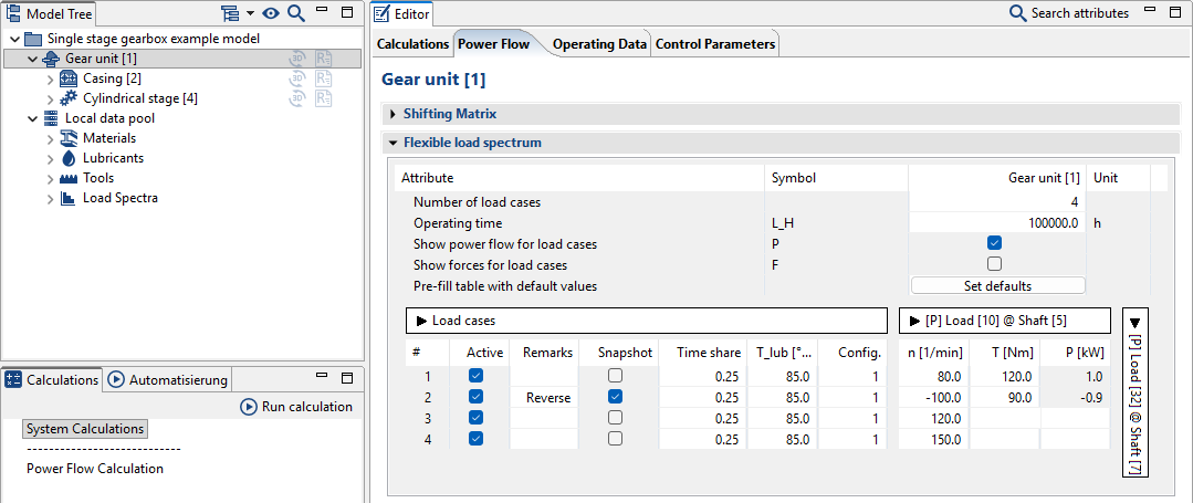
Flexible load spectrum editor
A button has been added to the input editor to automatically populate the "percentage" (uniform), "oil temperature," and "configuration" columns for load cases in a flexible load spectrum.
Import and export of REXS 2.0.0 models is now supported (see www.rexs.info).
An issue with exporting REXS files for models with "catalog bearings with internal geometry" has been corrected.
Previously, mass calculations for FE wheel bodies used the background FE mesh, which extended to the base of the teeth. Going forward, the FE mesh from the 3D View will be used instead, as the previous geometric overlap between the gear and the FE wheel body could result in an overestimated mass in some cases.
In certain cases, changing the number of planets in a planetary gear could cause inconsistencies in the report output. This issue has been corrected.
Bevel gear stage design using the gear pre-dimensioning assistant now calculates safety factors according to ISO 10300 (2023) instead of ISO 10300 (2014) as used previously.
Spline connections can now be calculated using the FKM Guideline in flexible load spectra.
An issue with displaying the number of load cycles for planetary stages in reports has been corrected. This only affected calculations according to DIN 3990 and related additional calculations.