Bevel gear calculations
The FVA-Workbench includes a multitude of calculation options for bevel and hypoid gearsets with different levels of complexity and possible applications. This includes design calculations, safety and load capacity calculations based on geometry data, and local calculation methods using manufacturing simulation or precise description of the microgeometry for the 3D tooth surface.
Various calculation options are available, depending on the level of detail with which the bevel gear geometry is described.
 Bevel gear sets |  Bevel gear sets with shaft angle > 90° |  Hypoid gear sets | 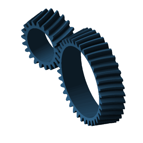 Hypoid gear sets with shaft angle < 90° |  Spur gears |
Geometry
Geometry design according to ISO 23509
The geometry design according to ISO 23509 module can be used as a link between standard geometry-based methods and advanced local calculations. If the gearbox model was created using Preliminary gear design, all attributes required for the bevel gear stage already contain default values for performing the geometry design in accordance with ISO 23509.
The result of this design calculation is the standard.kgd internal interface file, which can be used to calculate the meshing conditions of the gear pair and adapt the microgeometry to make it suitable for industrial application.
Thus, the local calculations can approximate the actual load capacity behavior so that significant factors (such as microgeometry, deformation, and relative position changes under load) which would have little or no effect in a standard calculation are considered.
Importing bevel gear geometry
The following input options are available for describing the bevel gear geometry, including microgeometry:
Import of common company interface machine setting data (basic geometry and full machine setting data) via a standard.kgd file.
Import of free 3D bevel gear geometry according to KIMoS 3D neutral data and the associated basic geometry data.
Specification of basic geometry data according to ISO 23509 (machine setting data is calculated and imported internally).
After a successful import using one of the three input options described above, the data for the bevel or hypoid gear is available for all local gear calculations as well as for load capacity calculations according to standards and classification societies.
To ensure consistency with the machine setting data, the geometry attributes are locked in the Editor and cannot be specified manually.
For calculations according to standards and classification societies, the basic geometry data (e.g.; from diagrams or dimensioning sheets) can also be manually specified under the "main geometry" tab in the Editor. However, local gear calculations cannot be enabled due to the missing microgeometry. The available calculation methods are summarized in the standard load carrying capacity and classification society sections.
Importing measurement data
Knowledge of the exact flank geometry is required to perform local stress and load capacity calculations. The measurement data import feature in the FVA-Workbench can be used to import and process actual bevel gear measurement data for the tooth contact analysis. Outliers are removed from the measurement data and flank deviations (fcb, fcp, fv, fHb, fHa) between the nominal geometry and the actual geometry represented by the measurement data are calculated.
Notice
The process for importing measurement data is described in detail in the Bevel Gear Measurement Data Processing tutorial.
The measurement data import wizard can be used to interactively select and remove outliers from the measurement data.
The following options are available for tooth contact analysis based on 3D measurement data:
Indirect use via consideration of flank deviations.
Direct use by considering flank deviations and using measurement data to generate fitting surfaces.
Fitting surfaces
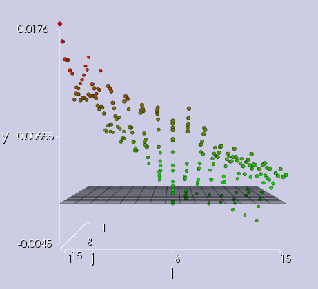
The foundation of every local calculation is a mathematical representation of the tooth flank geometry (including microgeometry) that is as accurate as possible. This is achieved using fitting surfaces, as they ensure quick access to any point on the flank. To assess the quality of the fitting surfaces, diagrams are available for the flank and root areas which show the deviation of the actual geometry (calculated fitting surfaces) from the nominal geometry (calculated points from the manufacturing simulation or imported 3D geometry). The maximum absolute deviation is shown and marked in the diagram. This makes it possible to check the coverage of the usable flank with calculation points or the location of the points from the imported 3D data.
Mathematical description of the tooth surface
NURBS surfaces are now also available as an alternative to Bezier surfaces for the mathematical description of the tooth flank and root areas in local calculations. NURBS surfaces are configured by specifying the polynomial degree and the number of control points. The NURBS surface approach is particularly advantageous for gears with relief (tip relief, end relief, protuberance), forged differentials (complex root geometry characterized by strong changes in the toe and heel area), and recalculation of gear damage specified via 3D measurement data.
Load capacity calculations
Standard load capacity
The only required input variables for calculations according to standard methods are the macrogeometry of the bevel gear, the operating conditions (consisting of speed, torque, and type of operation), and the material and lubricant information. These load capacity verifications are based on conversion of the bevel gear geometry into a suitable virtual cylindrical gear that approximates the meshing conditions of the bevel gear to be calculated. This results in the safety factors, which make it possible to make statements about the load capacity of the gear under the specified load. The following calculations can be used for recalculation of hypoid gears as well as non-axially offset bevel gears:
Determination of virtual cylindrical gears for bevel and hypoid gears according to various methods
Calculation of load capacity acc. to ISO 10300 (2014 edition)
Calculation of load capacity acc. to FVA 411 (2008)
Calculation of load capacity acc. to Niemann/Winter (1986)
Calculation of load capacity acc. to Niemann Volume 2 (1965)
Calculation of the risk of flank fracture acc. to FVA 240-II
Calculation of the risk of flank fracture acc. to Witzig/Boiadjev from FVA 556 III
Micropitting resistance acc. to FVA 516 (2011)
Scuffing resistance acc. to FVA 519 (2013)
Scuffing resistance acc. to ISO/TS 6336-20 -> successor to ISO/TR 13989-1 (2000 edition)
Scuffing resistance acc. to ISO/TS 6336-21 -> successor to ISO/TR 13989-2 (2000 edition)
Calculation of the efficiency and power loss acc. to Wech (1987)
Calculation and output of the gearing forces
Consideration of tolerances according to ISO 17485 (2006 edition) for displacements and deviations
The following additional calculation rules are also valid for non-axially offset bevel gear units, without restriction:
Calculation of load capacity acc. to ISO 10300 (2001)
Calculation of load capacity acc. to DIN 3991
Calculation of wear acc. to Niemann/ Winter
Load capacity calculations with single-stage load spectra are integrated into the load capacity calculations according to DIN 3991, ISO 10300 (2014), AGMA-C10, and FVA 411, and can be activated for system and single-component calculations.
Classifications
Marine classification society and AGMA rules can also be calculated in addition to standard calculation methods. The macrogeometry dimensions of the bevel gear, the operating conditions, and the material and lubricant specifications are required to perform the calculation. The following current calculation methods are available:
Load capacity acc. to AGMA 2003-C10
Load capacity acc. to American Bureau of Shipping 2016
Load capacity acc. to Bureau Veritas 2014
Load capacity acc. to Det Norske Veritas/Germanischer Lloyd 2015
Load capacity acc. to Lloyd’s Register 2015
Load capacity acc. to China Classification Society 2015
Load capacity acc. to Russian Maritime Register of Shipping
The following calculation methods from previous editions are also available:
Load capacity acc. to AGMA 2003-B97
Load capacity acc. to AGMA 2003-A86
Load capacity acc. to Det Norske Veritas 2003
Load capacity acc. to Det Norske Veritas 1993
Load capacity acc. to Germanischer Lloyd 1998
Load capacity acc. to Lloyd’s Register 1998
Advanced gear calculations
Advanced gear calculations use simulation of the load-free tooth contact analysis to realistically represent complex contact conditions. In this process, the meshed working flanks are brought into the expected relative position and rolled against each other.
The required nominal geometry of the gear is either determined in a manufacturing simulation or specified as free 3D bevel gear geometry (see Importing bevel gear geometry). During the import, all information required for a manufacturing simulation, such as the basic geometry, tool data, and kinematics including additional movements, are taken from manufacturer-specific interfaces (e.g.; KIMoS neutral data) and converted to the universal bevel gear cutting machine. The tooth flanks, including the tooth root area, are simulated point-by-point to represent the nominal geometry of the gear.
The tooth flanks and the root area can be represented in a mathematically closed manner based on the fitting surfaces from the nominal geometry. The fitting surfaces can also be used to estimate the ratio of curvature on the tooth flanks.
The local stress, and subsequently the local load capacities and safety factors, are calculated based on the results of the load-free tooth contact simulation.
Load-free tooth contact simulation
In the load-free tooth contact simulation, the meshed tooth flanks with fitting surfaces are rolled against one another. By definition, the concave pinion is in mesh with the convex ring gear flank in drive operation, and the convex pinion is in mesh with the concave ring gear flank in coast operation.
The load-free tooth contact simulation delivers the following results, taking into account the relative position of pinion and gear to each other as specified or calculated in the system calculation:
Ease-off
Deviations in the theoretical (uncorrected) roll ratio during mesh are plotted on the crown gear flank in the axial cutting plane in the ease-off diagram. This can be used to draw conclusions on the effectiveness of the microgeometry design.
Load-free contact pattern
The size and position of the load-free contact pattern with a spotting thickness of 6 µm is plotted on the pinion and crown wheel flanks in the axial cutting plane in the load-free contact diagram. Any meshing interference (meshing of the tooth tip in the tooth root area of the mating gear) on the working flank is shown in red. The tip clearance in the root area is also plotted.
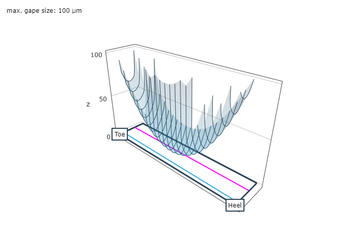
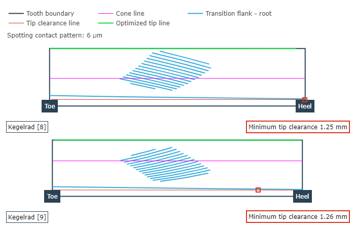
Representation of the ease-off over the ring gear flank (left), and load-free contact pattern of wheel and pinion (right).
The following optional additional results can also be calculated:
Circumferential backlash
As bevel gears always have flank modifications in practice, the circumferential backlash is not constant when considered across the meshing positions. The difference between the minimum and maximum circumferential backlash results from overlapping the working variations in drive and coast operation. Insufficient circumferential backlash can lead to jamming due to expected relative position deviations under load. Too much circumferential backlash can lead to increased running noise and reduced load capacity. The microgeometry, the mounting position, and the relative position changes under load are all considered in the calculation of the circumferential backlash.
Retractability (mountability) of the bevel gear pinion
Retractability is determined based on the nominal installation position and, optionally, by specifying lowering of the ring gear.
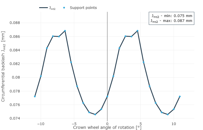
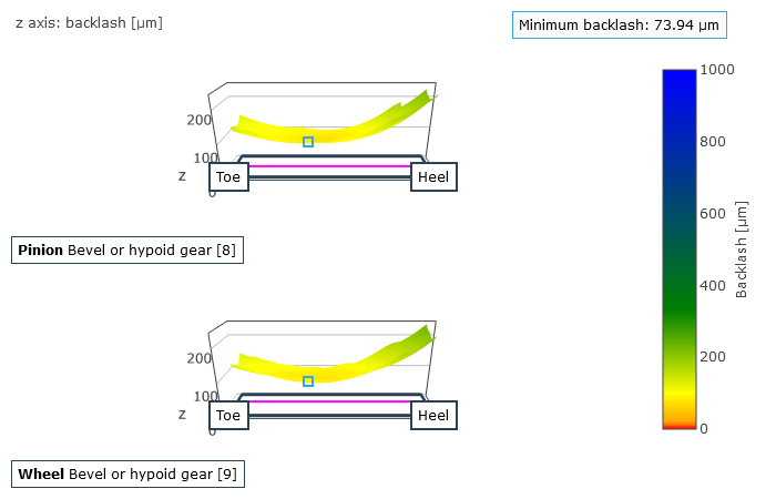
Mean circumferential backlash over the angle of rotation of the ring gear (left), and rear flank clearance: gap between the mating flanks (right).
The results of the load-free tooth contact simulation are the basis for all subsequent calculations.
Retractability of the bevel pinion
A pinion is retractable if it can be rotated out of the mesh and the pinion only moves along the gear axis. As a result, the relative position of the axis of the pinion only changes in the axial direction out of the mesh. Retractability refers to both the mounting and disassembly procedures. This has an enormous influence, especially on the design of the casing. Whether or not the bevel pinion is axially retractable has a significant influence on the mounting and disassembly processes.
The minimum and maximum backlash over the axial displacement of the pinion are graphically represented as a result of the retractability calculation. The following three cases can occur:
Retractable
The curves of the minimum and maximum backlash increase monotonously. The lowest values are located at the coordinate origin.
Conditional retractability
The lowest value of the minimum backlash is negative and the lowest value of the maximum backlash is positive. This means that there are meshing positions in the corresponding axial pinion positions in which the pinion and the crown wheel do not interpenetrate. Jamming while rotating the pinion and crown wheel toward each other can only be avoided under ideal conditions. Retractability cannot be assumed without additional testing.
Not retractable
The minimum values are negative. This means that meshing interpenetration is calculated for all axial pinion positions with negative minimum and maximum backlashes. The gearing jams and the pinion cannot be moved axially.
Cutter head radius | Retractability without lowering of the crown wheel | Retractability with lowering of the crown wheel |
|---|---|---|
 | ||
rco = 55mm | 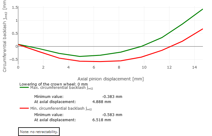 Case 3: not retractable | 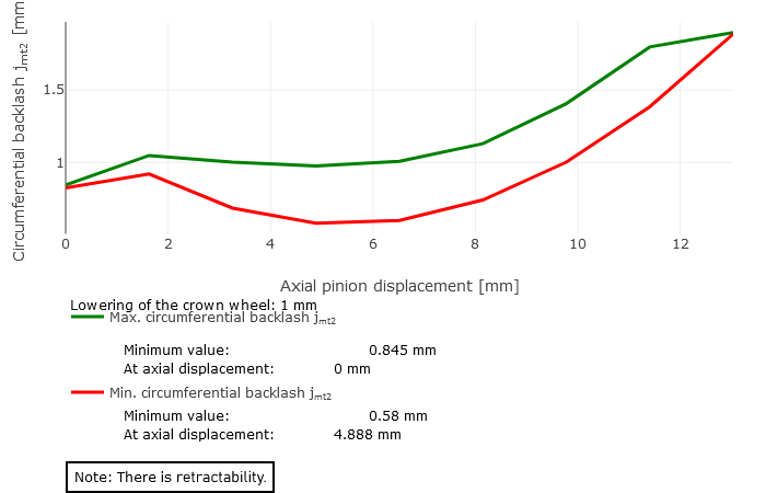 Case 1: retractable (Lowering of crown wheel = 1 mm) |
rco = 62mm | 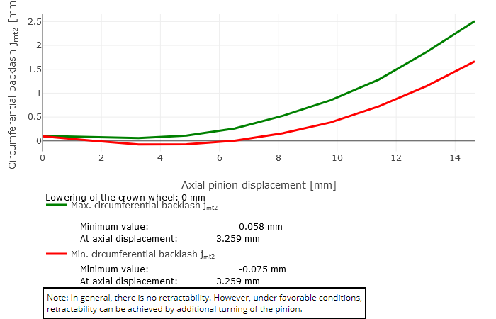 Case 2: conditional retractability | 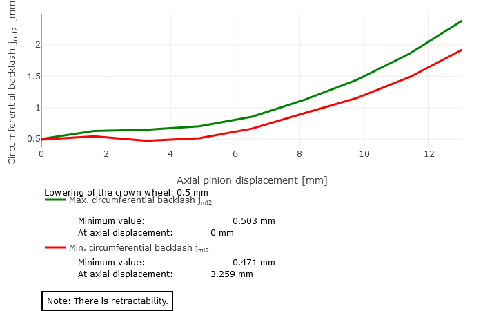 Case 1: retractable (Lowering of crown wheel = 0.5 mm) |
rco = 75mm | 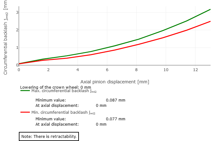 Case 1: retractable | |
Local stress calculation
Building on the results of the load-free tooth contact simulation, the local stress is calculated based on the influence coefficient method, a numerical calculation method with which the load and stress distribution can be efficiently calculated at discrete points.
The following methods can be used for calculation of the tooth stiffness, depending on the model and the scope of the calculation:
BEM influence coefficient method
Combination of BEM and FEM influence coefficients for the wheel body
FEM influence coefficient method
By default, the stiffness of the wheel body is approximated by an elastic half-space. Optionally, a wheel body and its clamping can be explicitly specified as complex wheel body geometry. Wheel bodies can easily be loaded as CAD geometry, positioned, and meshed in the FVA-Workbench. The influence coefficients are calculated according to FVA Research Project 223 XVI ("BECAL Wheel Bodies," TU Dresden IMM, Prof. Dr. Berthold Schlecht), taking the specified wheel body into consideration. The deformation and stress calculations for bevel and hypoid gears can be performed using FEM, which makes it possible to calculate the 3D tooth root load capacity. This more detailed calculation of the three-dimensional deformation also makes it possible to calculate and evaluate the working backlash on the rear flank.
The tooth deformation and tooth root stresses are calculated using the nominal geometry, which is either determined from a manufacturing simulation or imported via 3D nominal data. Multiple normal sections are determined along the face width from the fitting surfaces which describe the flank and root areas, each of which then describes the actual tooth and root area as well as how it changes over the face width. The tooth deformation and tooth root stresses are then calculated using the Boundary Element Method (BEM) based on these normal sections (see FVA Research Project 223 XI, "BECAL – Load and Stress Model," TU Dresden IMM, Prof. Dr. Berthold Schlecht).
The user is provided with the locally solved load and stress distribution as well as the local sliding speeds as a result. This is used to determine a resulting efficiency for the stage; the gear stiffness profile across the meshing positions and the working variation are determined from the calculated geometry and the contact description. The working variations are a measurement for the running behavior of the gear at an operating point. The maximum root stresses across all meshing positions are represented over the face width.
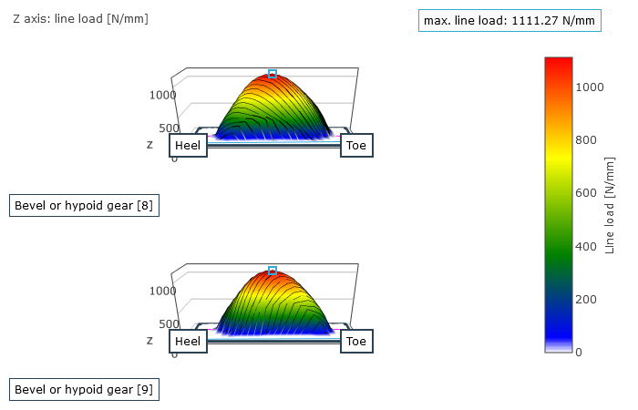
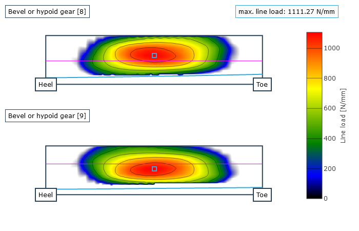
Representation of the load distribution on the flank
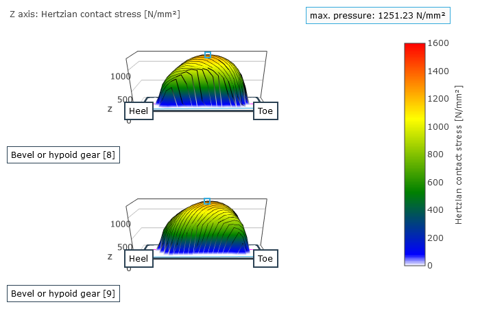
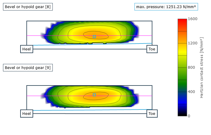
Representation of the pressure distribution on the flank
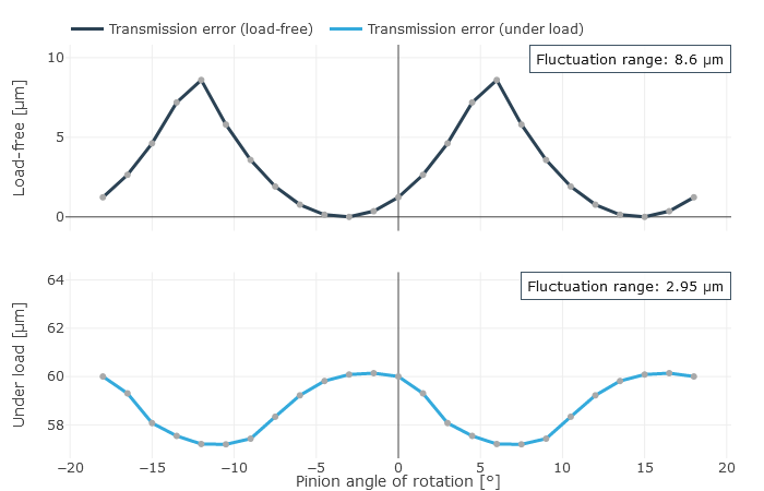 Transmission deviation | 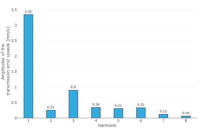 Transmission deviation spectrum |
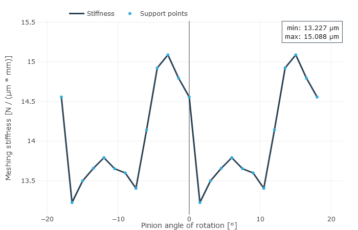
Gear stiffness
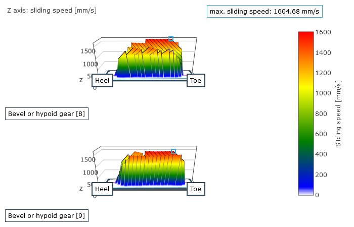
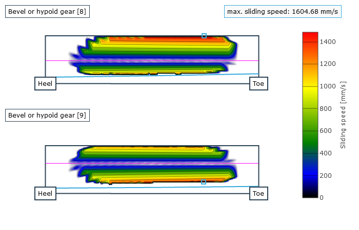
Sliding speed in the contact area
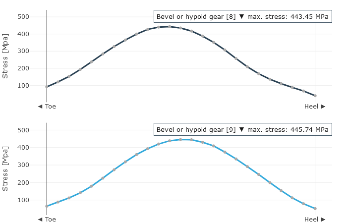
Tooth root stress over the face width
Calculation of the working backlash
The working backlash refers to the circumferential backlash under load, which means that the deformation of the teeth and the wheel body are taken into account in addition to the load-induced relative position changes when calculating the operating backlash. The FE influence coefficient method is used as a basis for the working backlash, which makes it possible to calculate the deformations. Two methods are available for calculating the working backlash: the linear and iterative calculation methods. The iterative calculation method is recommended. It is more computationally intensive, but provides more precise results.
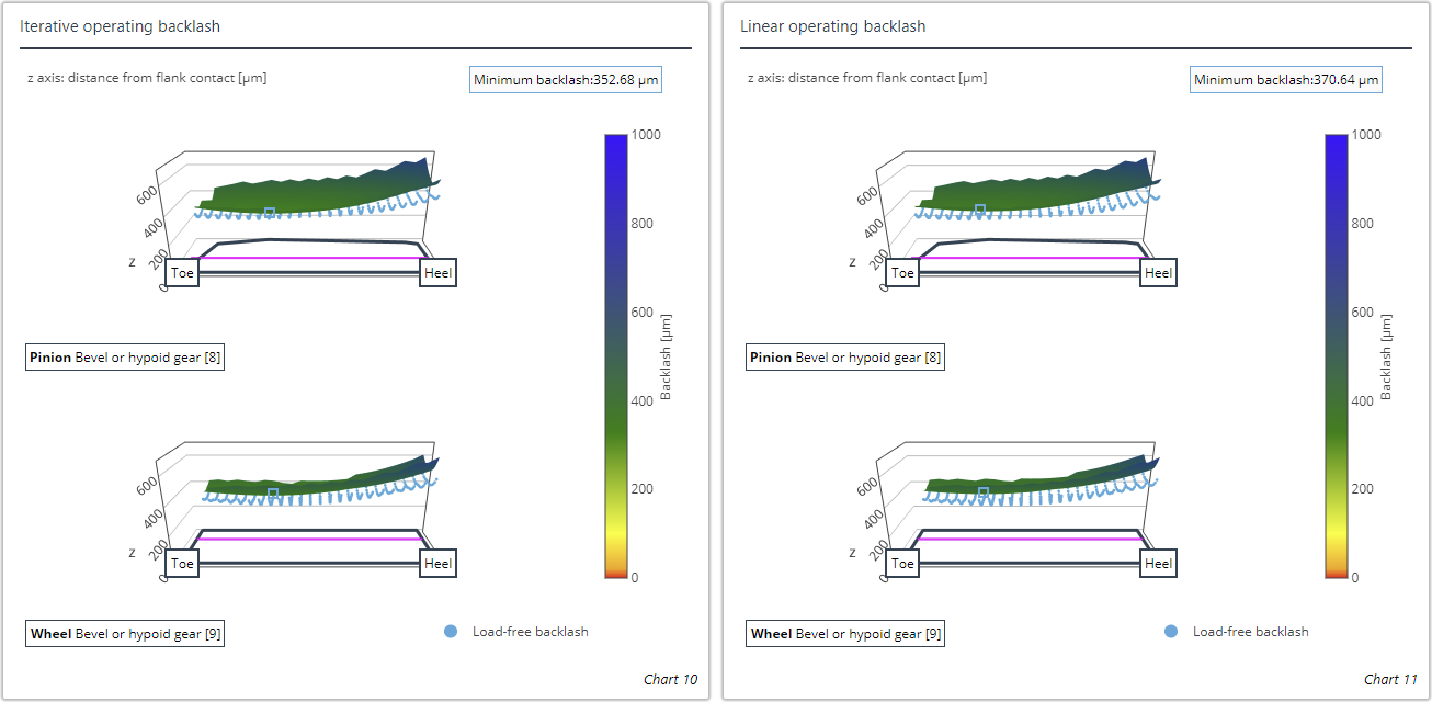
The load-free backlash (blue) can be shown in the diagram for quick comparison. The location with the minimum working backlash is also marked.
Local load capacity calculations
Various load capacity calculations can be performed based on the locally calculated stresses (Hertzian contact stress, tooth root stress), the local sliding speeds, and the specified oil and material information, roughnesses, temperatures, and lubrication conditions. The local load capacity calculations were revised in FVA Research Project 223 XII ("BECAL - Tooth Flank Damage Progress," TU Dresden IMM, Prof. Dr. Berthold Schlecht).
Notice
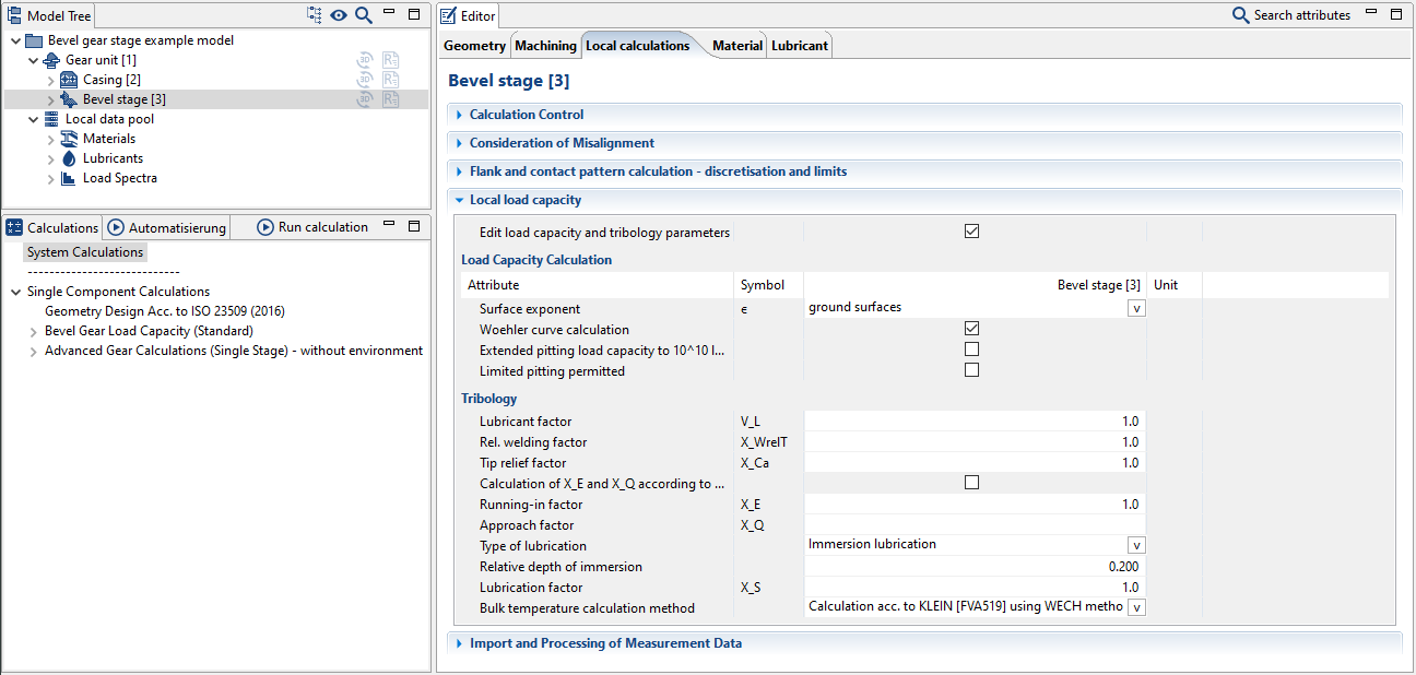
Calculation with individual tribology and material specifications
Roughness specification
The roughness of the flank influences the coefficient of friction as well as the flank load capacities. The determined roughness depths in the tooth root are used for calculation of the tooth root load capacity acc. to ISO 10300-3.
Specification of a Woehler S-N curve, optional specifications for internal Woehler S-N curve calculation
Internal calculation of the Woehler S-N curve is based on the material according to ISO 10300-2. Advanced pitting load capacity up to 1010 load cycles can also be activated. In this case, factor ZNT in the fatigue resistance area sinks to a value of ZNT = 0.85. By allowing limited pitting damage (acc. to ISO 10300-2:2014), a specific amount of pitting can be tolerated. Specification of the surface exponent ε is used to calculate the micropitting load carrying capacity acc. to FVA 516 and includes specification of the hard fine machining of the flank.
Specification of the XW , XQ , XE , XS, and XCA factors or activation of internal calculation
The run-in factor XE and the approach factor XQ influence the scuffing load capacity. They can be calculated internally acc. to FVA 519.
Specification of the bulk temperature calculation method
The bulk temperature or the friction coefficient can be specified, depending on the bulk temperature calculation method. Alternatively, the following three calculation approaches can be used:
The bulk temperature acc. to KLEIN (FVA 519 I) is determined using the power loss acc. to WECH.
The HOMBAUER (FVA 516 I) approach follows the iterative determination of the power loss, which is used to calculate the bulk temperature.
In the estimation acc. to KLEIN (FVA 519 I) the bulk temperature is determined as a function of the pinion torque.
The local safety values are determined similar to the standardized calculation methods; therefore, the same strength values are used. These local observation methods are based on experimentally supported analyses in FVA Research Project 411 for hypoid gear load capacity calculations.
The safeties against pitting according to FVA 411 and micropitting according to FVA Research Project 516 ("Hypoid Micropitting," TU München FZG, Prof. Dr. Karsten Stahl) of the tooth flank along with the safety against flank fracture acc. to ISO 10300 are calculated as a result; due to the increased contact temperature, the safety against scuffing acc. to FVA Research Project 519 ("Hypoid Scuffing," TU München FZG, Prof. Dr. Karsten Stahl) is also calculated. The local calculation results for the safeties against micropitting, pitting, scuffing, and flank fracture, as well as the significant intermediate results (local flash temperatures, local coefficients of friction, and the relative lubricating film thickness) are available as graphic outputs.
Calculation of the local load capacity should be considered in the overall system. The system calculation considers the stiffness of all components in the gearbox and uses them to calculate the occurring deformation. The relative displacements of the bevel gear stage are calculated from the shaft bending line and are automatically considered. This makes it easy to calculate and evaluate bevel gear stages, taking all relevant influences into account.
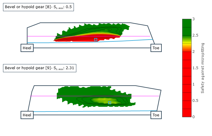 Local safety against micropitting | 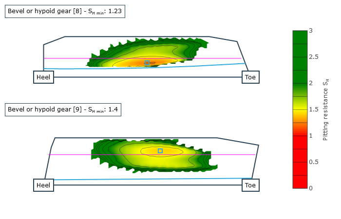 Local safety against pitting | 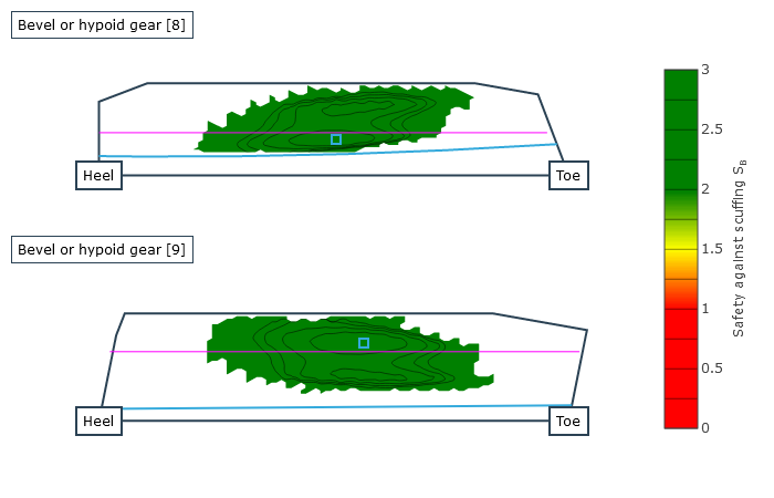 Local safety against scuffing |
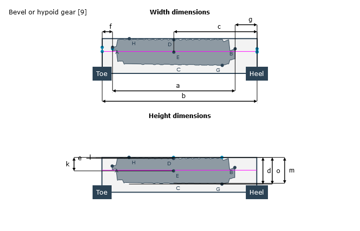
Measurement of the contact pattern
The load-free contact pattern is the key parameter during assembly; it is used to determine the configuration of the bevel gear stage and how the bevel gears are aligned with each other. If the nominal mounting position is not maintained it can lead to reduced load capacity, increased noise development, or meshing interference. Guidelines for characterizing and measuring load-free and loaded contact patterns were developed in FVA Research Project 223 XV ("Contact Pattern Measurement," TU Dresden IMM , Prof. Dr. Berthold Schlecht) in order to be able to compare the contact pattern with the calculation. The bevel gear calculation was also enhanced to output the position of these contact patterns relative to the tooth boundary.
The investigations in the research project showed that the load-free and loaded contact patterns in the FVA-Workbench aligned very closely with the actual contact patterns.
Notice
Calculation of the load-free contact pattern
The "load-free tooth contact simulation" advanced gear calculation should be run as a single component calculation without specifying the load-dependent relative positions.
If the drive torque is sufficiently low a system calculation can also be performed.
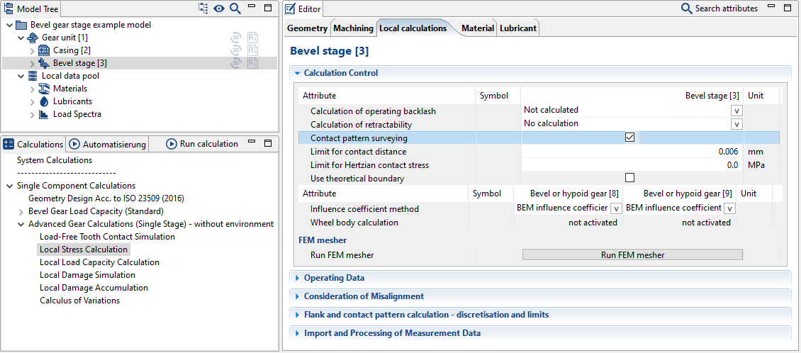
The contact pattern calculation can be activated in the Editor under the "calculations" tab. The "limit for contact distance" can be used to specify the thickness of the contact pattern paste or lacquer.
Calculation of the loaded contact pattern
A system calculation should be run using the existing drive torque with the additional "local stress calculation" activated. The load-dependent relative deviations are determined from the gear environment and included in the calculation.
The contact pattern calculation can be activated in the Editor under the "calculations" tab. The "limit for Hertzian contact stress" can be used to specify the desired contact pattern range.
Once calculated, these contact patterns can be used to check the installation. The influence of mounting dimension deviations and load-induced relative changes to the contact pattern can also be identified.
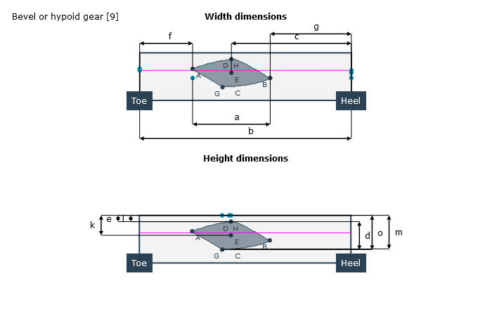
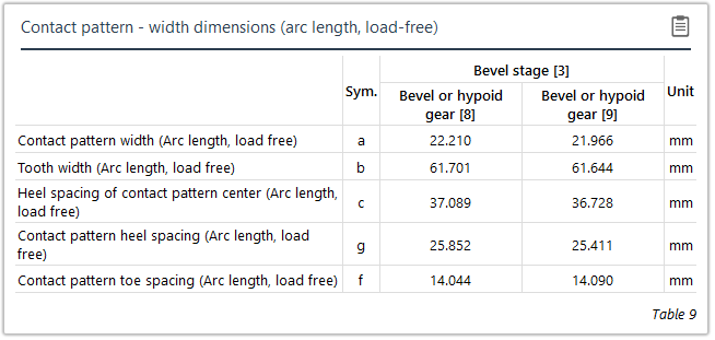
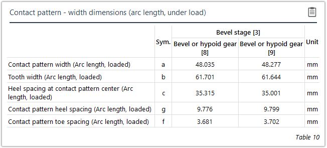
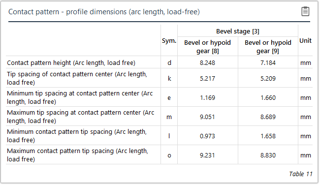
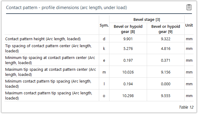
Both direct distances (chordal length) and distances measured along the flank surfaces (development dimensions) can be used for measuring the actual contact pattern on the tooth flanks.
Load-free contact pattern | Loaded contact pattern |
|---|---|
 |  |
 |  |
 |  |
Variational calculations
A specific characteristic of bevel gears is their sensitivity to displacement; i.e., changes to the size and location of the contact pattern with relative position deviations. Automatic variation of the torque and speed combined with load-dependent relative position deviations provides a quick overview of the changes to the local stresses and safety factors.
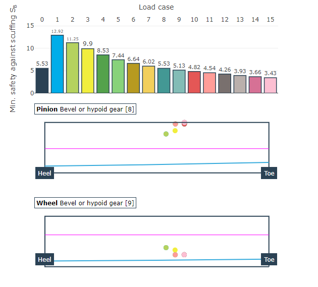
Representation of the minimum scuffing safety for each load case. The numerical value and the location of the minimum safety on the flank are also included.
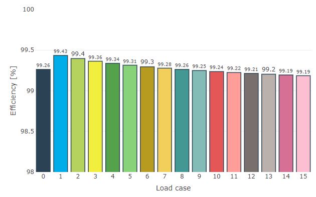
Representation of the efficiency for each load case.
Local damage accumulation load spectrum
The local damage accumulation calculation makes it possible to consider the actual load conditions, which change during the operating period, in the tooth contact simulation and subsequent local load capacity calculation. This gives users an initial indication of the location with the greatest damage, and thus the area at which pitting damage or root damage is most likely to occur, as well as an estimate of the amount of fatigue.
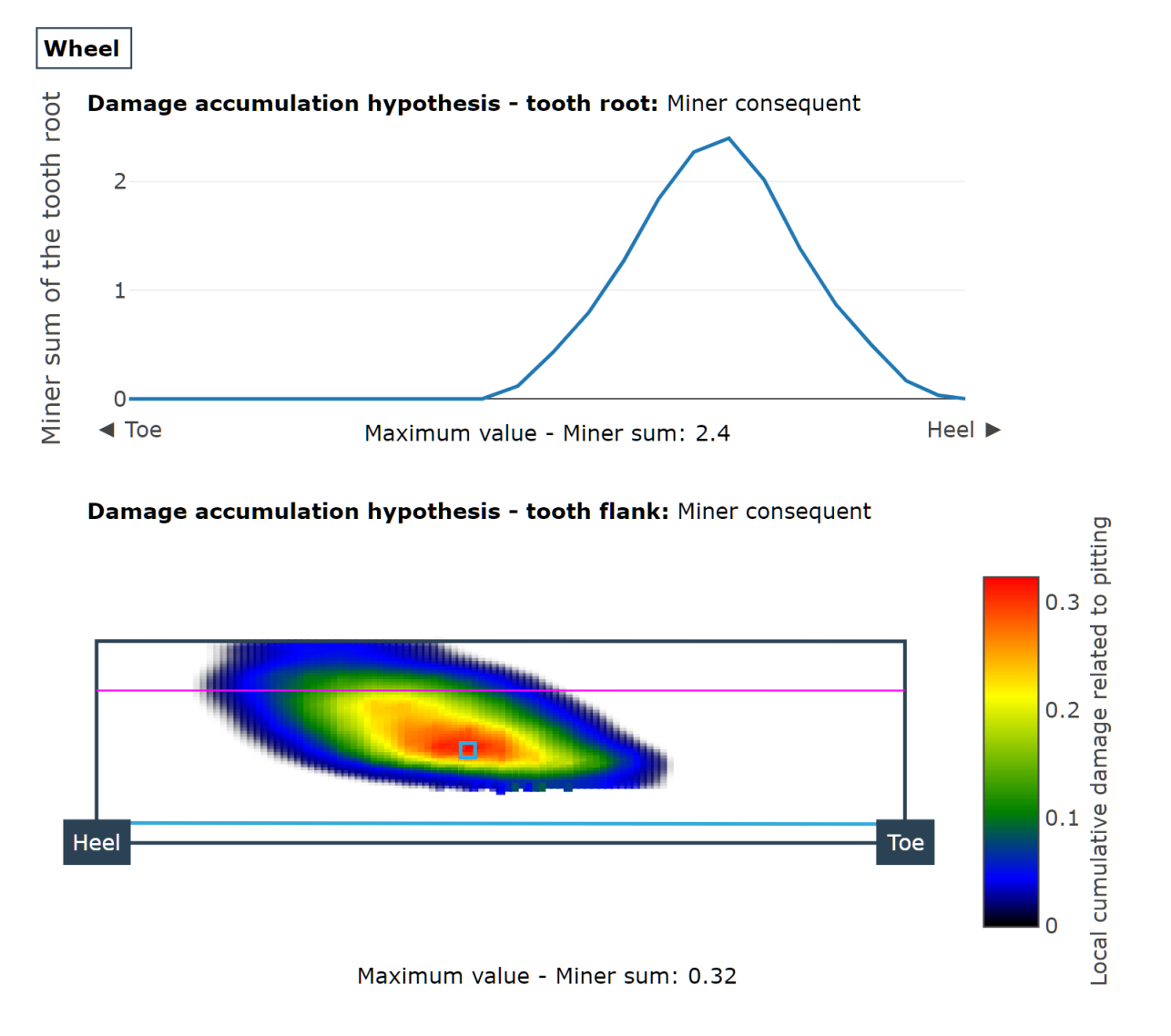
Damage accumulation for tooth flank and tooth root
Local damage simulation
A damage simulation can be performed for the tooth flank based on FVA Research Project 223 XII as an extension to the local load capacity calculation. Simulation of the micropitting and pitting growth is based on the determined load capacity, the associated cumulative damage, and the resulting change to the flank shape. As the simulation includes damage due to constant changes of the flank shape, both the interaction between micropitting and pitting damage as well as the influence of the damage on the flank load capacity can be modeled.
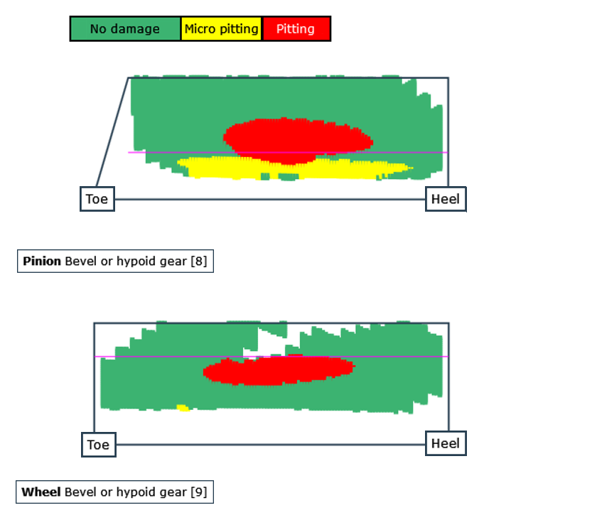
Damage progress on the flank