FVA-Workbench 8.0
Features
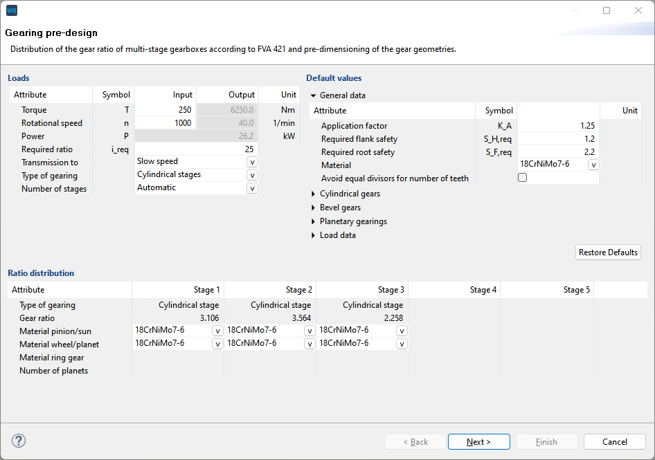
The new preliminary gear design module [WB_200.6] can be used to quickly and easily create gearbox models for further calculation in the FVA-Workbench. Once the load data and the gearbox structure have been specified, the number of gear stages and the geometry are determined automatically.
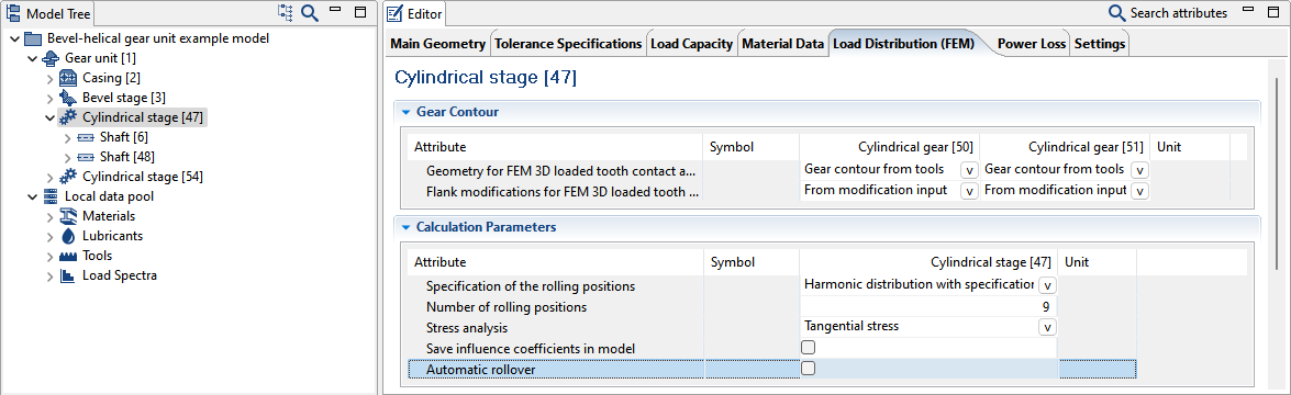
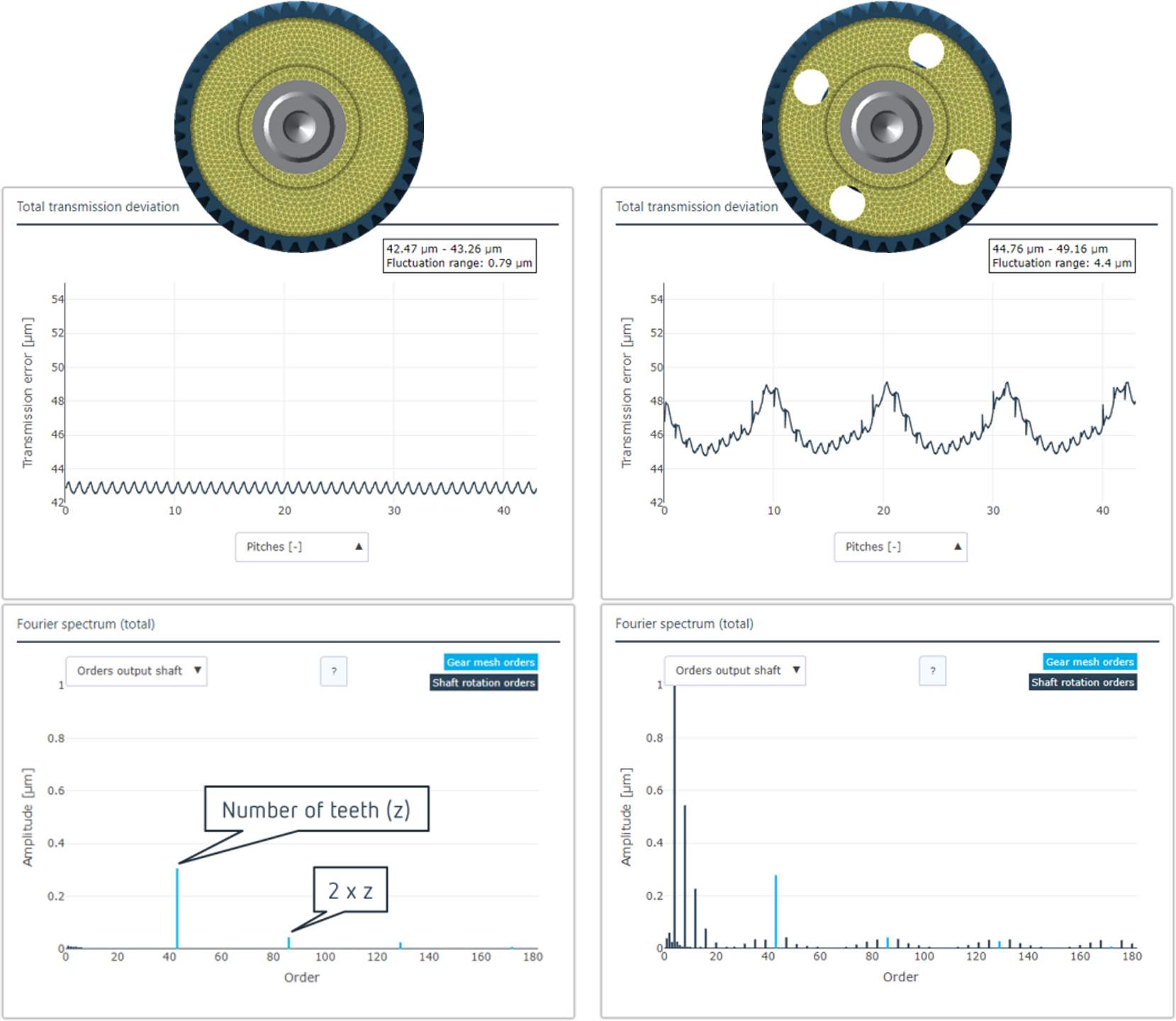
This new module [SYS_200.6] is very well suited for analyzing the operating behavior of gears with complex wheel body designs. The load distribution (FEM) is quasi-statically calculated for various meshing positions and aggregated across a full rollover.
In particular, design elements such as holes or webs in the wheel body lead to significantly different operating behavior, and dominant shaft rotational orders may appear in addition to the tooth meshing orders which correlate with the frequency of the design feature (hole, web).
The transmission deviation and its FFT analysis, and thus the Fourier spectrum of the deviation, are automatically determined across a full rollover. The contact line pressure and the tooth root stress are also determined for the full rollover.
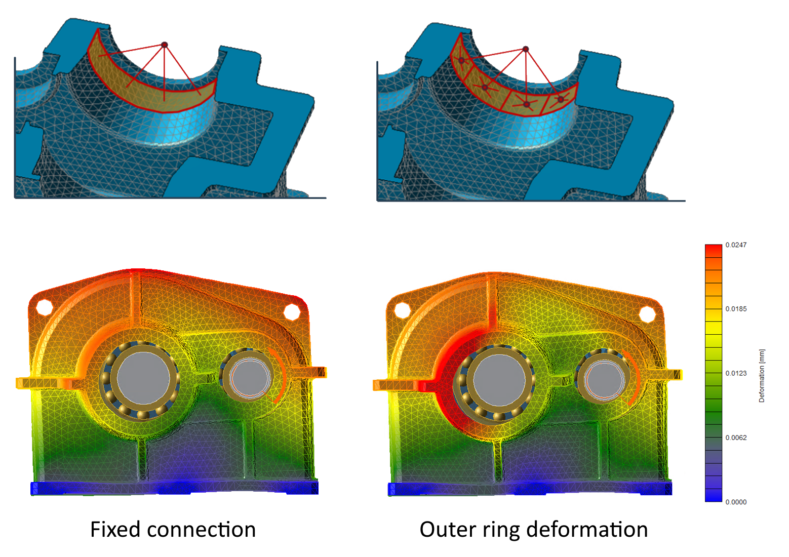
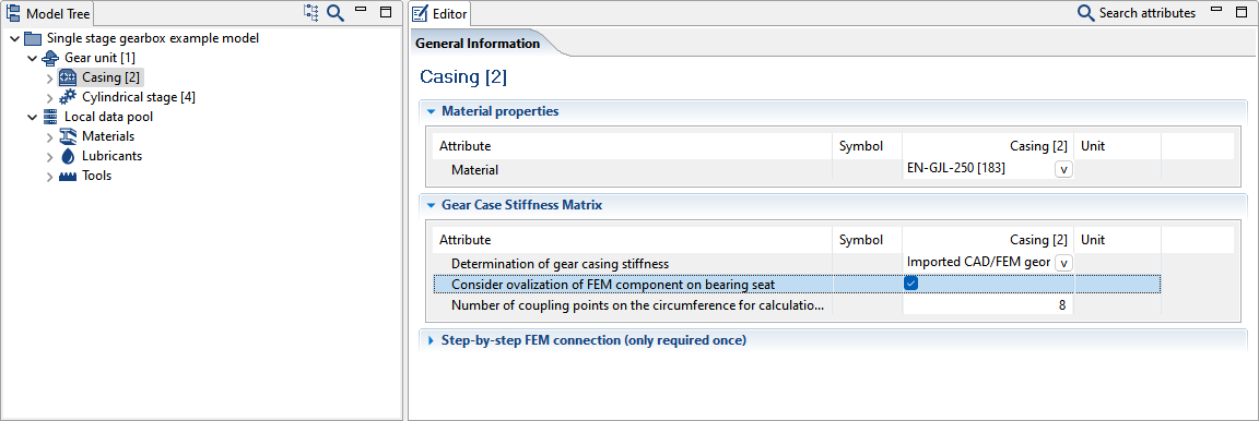
Ovalization of the FE component on the bearing seat is an advancement of the bearing modeling in the overall mechanical system. The bearing modeling, which previously used a rigid coupling element between the bearing seat and the bearing center, can now be discretized on the circumference. A reduction to multiple connection points over the bearing seat, and their iterative activation and deactivation during the calculation, enables targeted release of areas subject to tensile loads. Optionally, additional axial coupling points can be configured and axial forces can be targeted specifically to the casing.
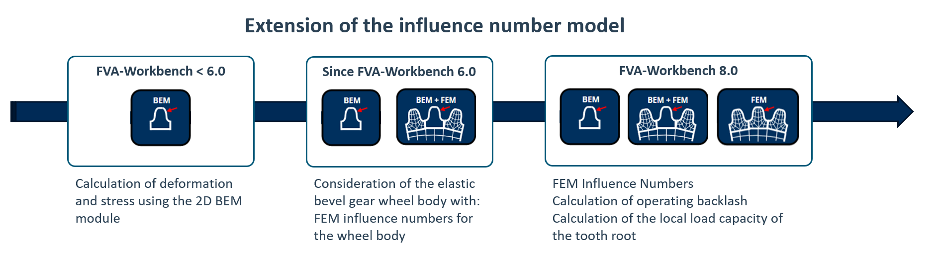
The deformation and stress calculations for bevel and hypoid gears can now be performed using FEM. This makes it possible to calculate the 3D root load carrying capacity. Due to the detailed calculation of the three-dimensional deformation, the operating clearance at the rear flank can also be calculated and evaluated.
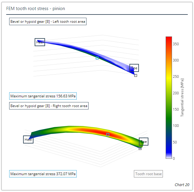
Representation of the tooth root stresses for the left and right tooth root is new
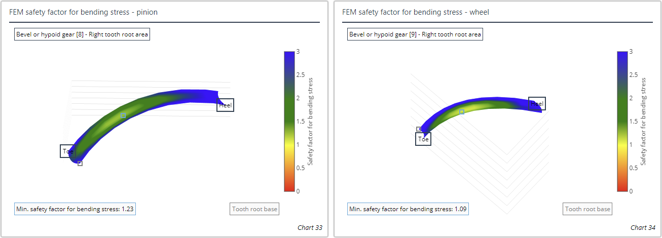
Representation of the root load carrying capacity for the left and right tooth root is new
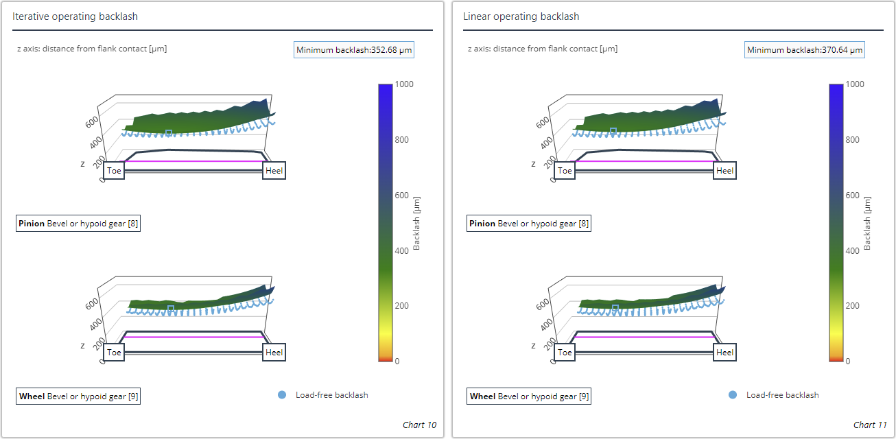
Representation of the load-free circumferential backlash and the load-affected operating clearance according to linear and iterative calculation methods is new
Right-click on a model snapshot to restore it. The current model is discarded and the input data of the selected model snapshot is used as the current model.
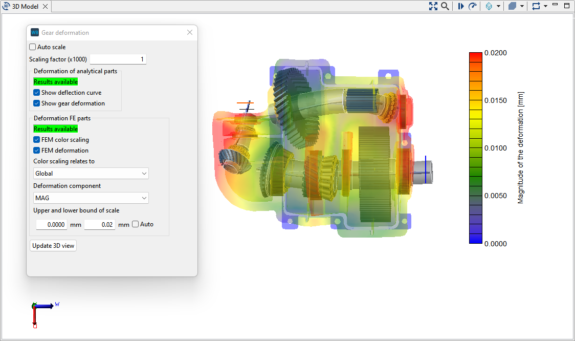
Display of gearbox deformation
Right-click on the 3D model to open the dialog for showing the gearbox deformation. The deformation of analytical and FEM components can be shown here.
The dialog has been extended as follows:
Automatic scaling factor
Indication of whether the calculation results needed for the display are available
Selection of the FE component which the color scaling should refer to
Selection of the deformation component to be displayed (magnitude/u/v/w direction)
The upper and lower limits of the color scale can be specified
Display of additional masses in the 3D model
Additional masses on shafts are now shown in the 3D model.
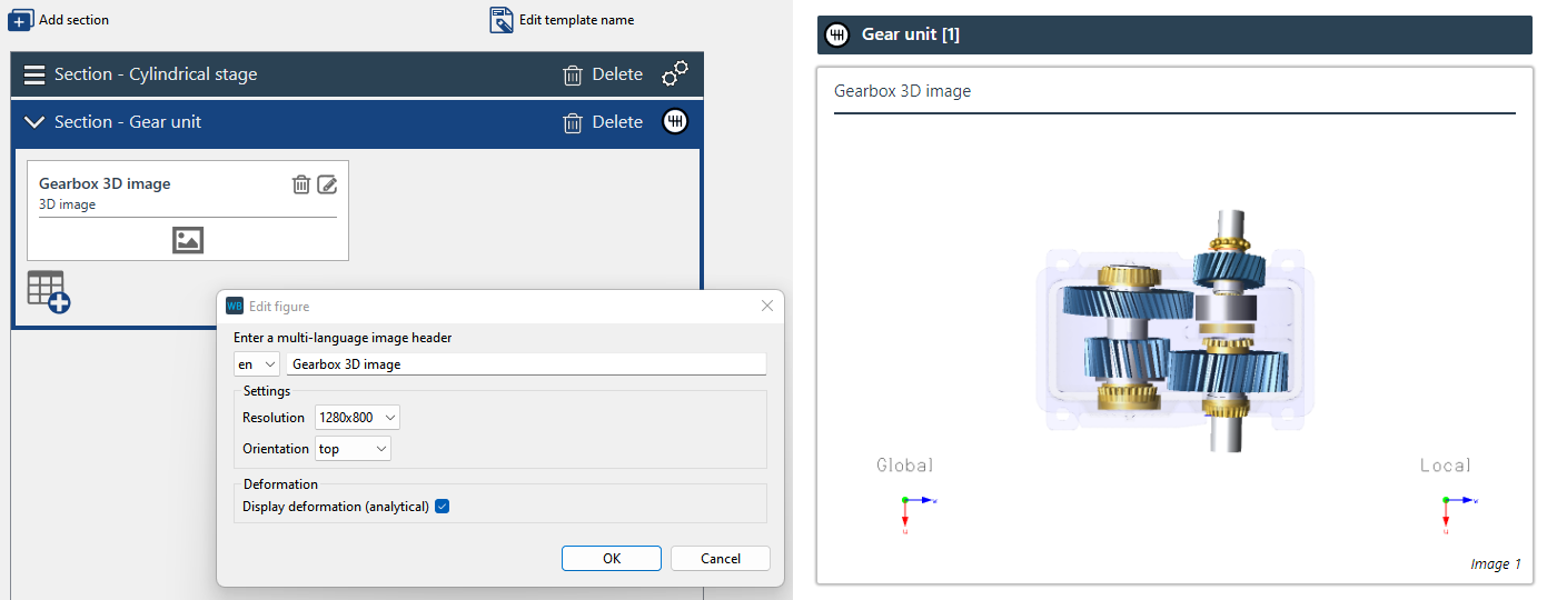
New display options for 3D images in the report
The following can now be individually configured in the report template for each machine element:
View of the gearbox model (above/below/left/right/front/back/ISO)
Display size or resolution of 3D images
Option to display the analytical gearbox deformation in the image (for gear unit and shafts only)
The global and local coordinate systems are also now shown in each image
Animation of gearbox kinematics in reports
A new block is available in the gear unit section of the report which shows the gear kinematics as a video. The following can be configured:
View of the gearbox model in the video (above/below/left/right/ISO)
Display size or resolution of the video
Length of the video in seconds (if a rotation axis is selected, the gearbox rotates 360° in the specified time)
Axis about which the gearbox rotates in the video (u, v, w, no rotation)
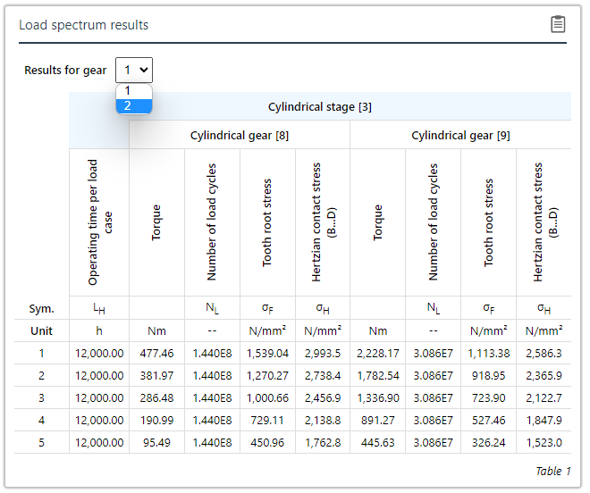
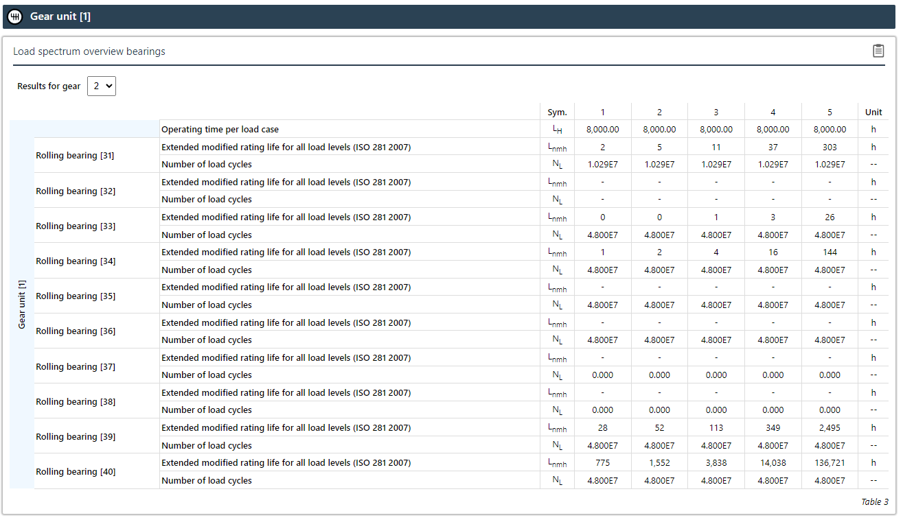
The results of load spectrum calculations can now be clearly shown with the new load spectrum table type. The results are shown for each load case. For multiple gears, the gear for which the results should be shown can be selected via drop-down menu. This table type is available in the report configurator for the cylindrical gear stage, cylindrical gear, and rolling bearing sections.
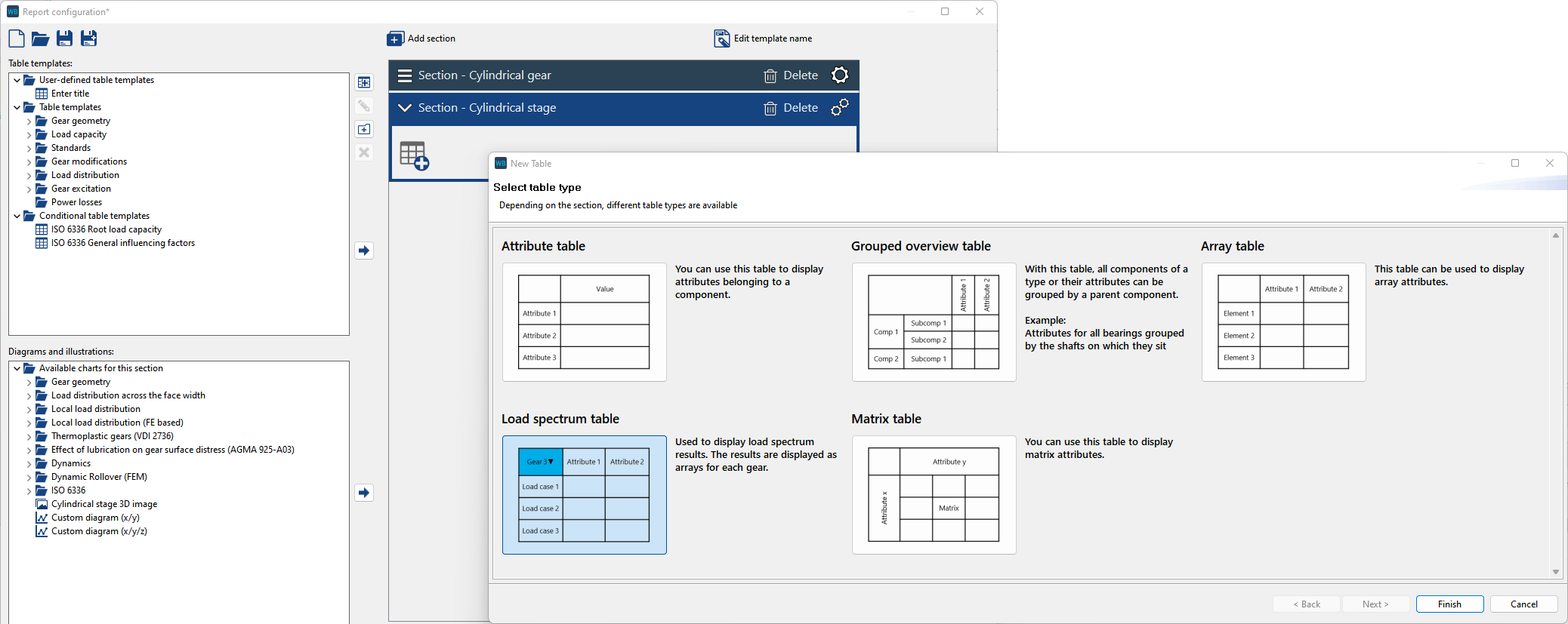
The load spectrum overview table type has also been introduced. The load spectrum results for all components of a type can be shown here. The different gears can also be switched. This table type can be added to the gear unit section.
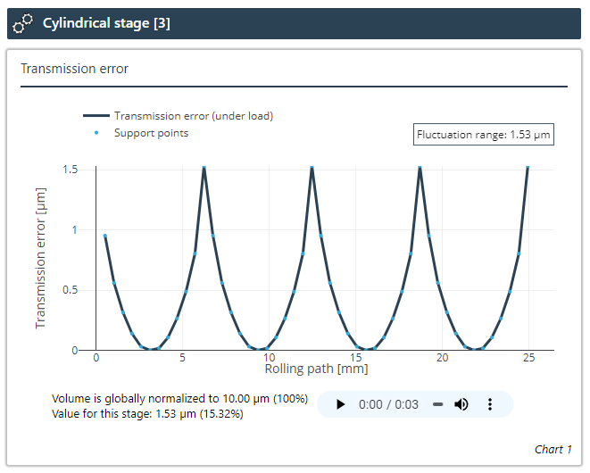
The transmission error diagram now includes an audio output of the noise generated by the stage. To do so, the profile of the transmission error is converted to a sound file. To enable comparison of the volume between different stages, the "transmission error for normalization of sound output" attribute for the gear unit can be used to set the variation range for which the volume should be at the maximum.
Cylindrical gears
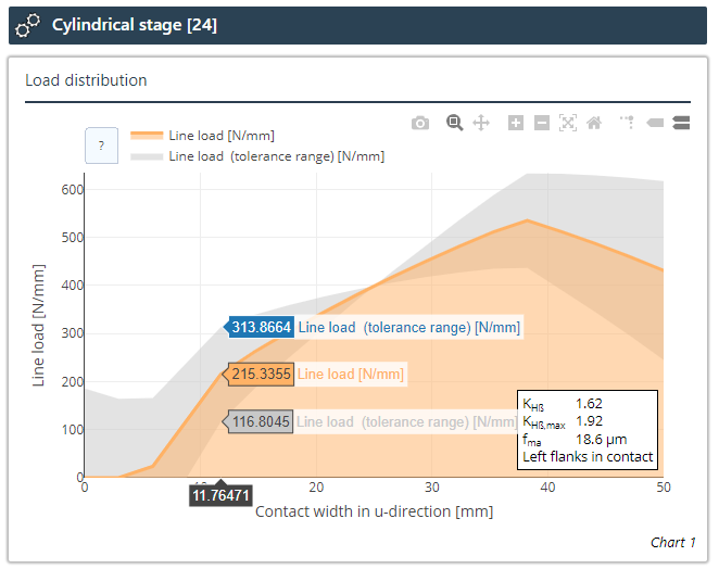
The load distribution graph shows the line load determined in the system calculation along the contact width. The face load factor KHβ is calculated by dividing the maximum line load by the mean value. The line load is initially calculated without consideration of manufacturing deviations. In addition, the line load is determined taking into account the manufacturing deviation fma. For this purpose, the larger of the two flank line deviations fhβ of pinion and gear is multiplied by a user-definable factor according to the gear quality and considered with both a positive and a negative sign (left or right tooth end is in front). The displayed value of the face load distribution, which takes this tolerance into account, is the greater of the two values calculated in this way. Any feedback effect of the manufacturing deviation on the total system calculation is not considered.
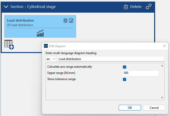
The display of the tolerances can be deactivated in the report configurator.
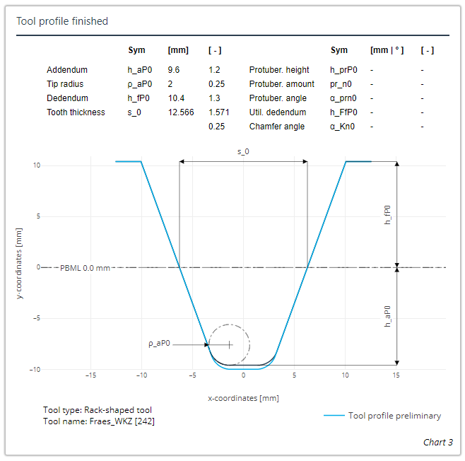
The contour of the rouging tool can now be shown in the finishing tool diagram.
Bevel gears
The spotting contact film thickness can now be set directly in the diagram via a slider.
The maximum distance from flank contact can now be set directly in the diagram via a slider.
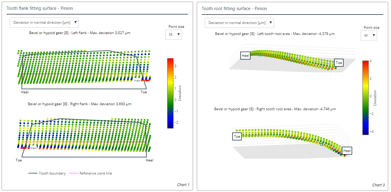
Deviation of the fitting surface to the point base for tooth flank and root
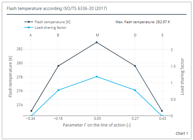
The diagrams for scuffing load capacity according to FVA 519, ISO/TS 6336-20:2017, BV (2014), DNV/GL (2015), DNV (2003), and DNV (1993) are new.
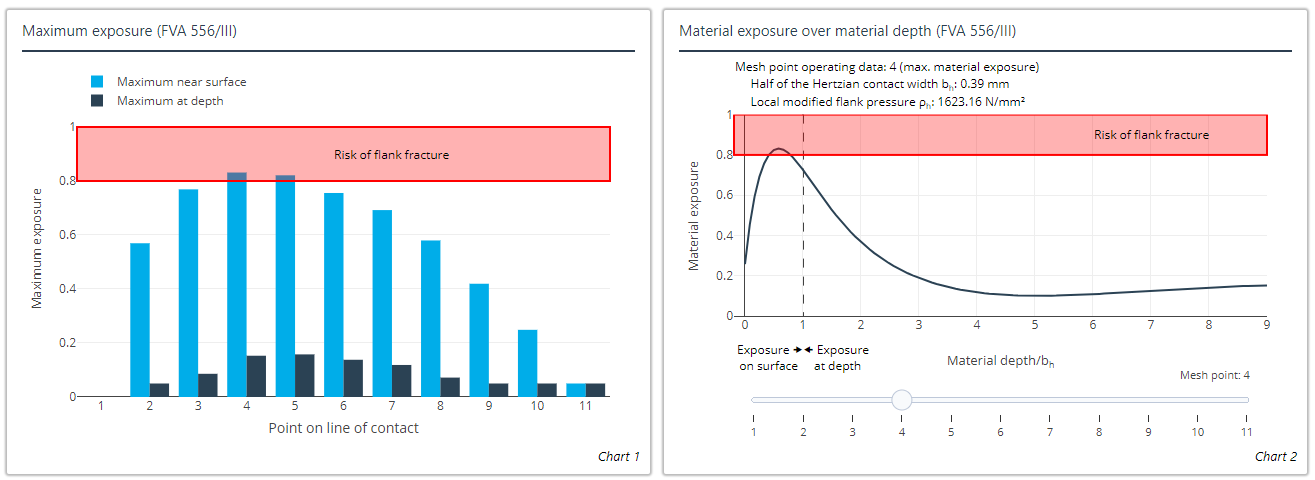
The diagrams for displaying the maximum exposure and exposure depth profile according to FVA 556/III are new.
Rolling bearings
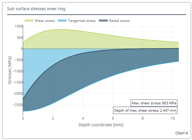
The diagrams for displaying the shear stress depth profiles for the inner and outer rings of rolling bearings are new.
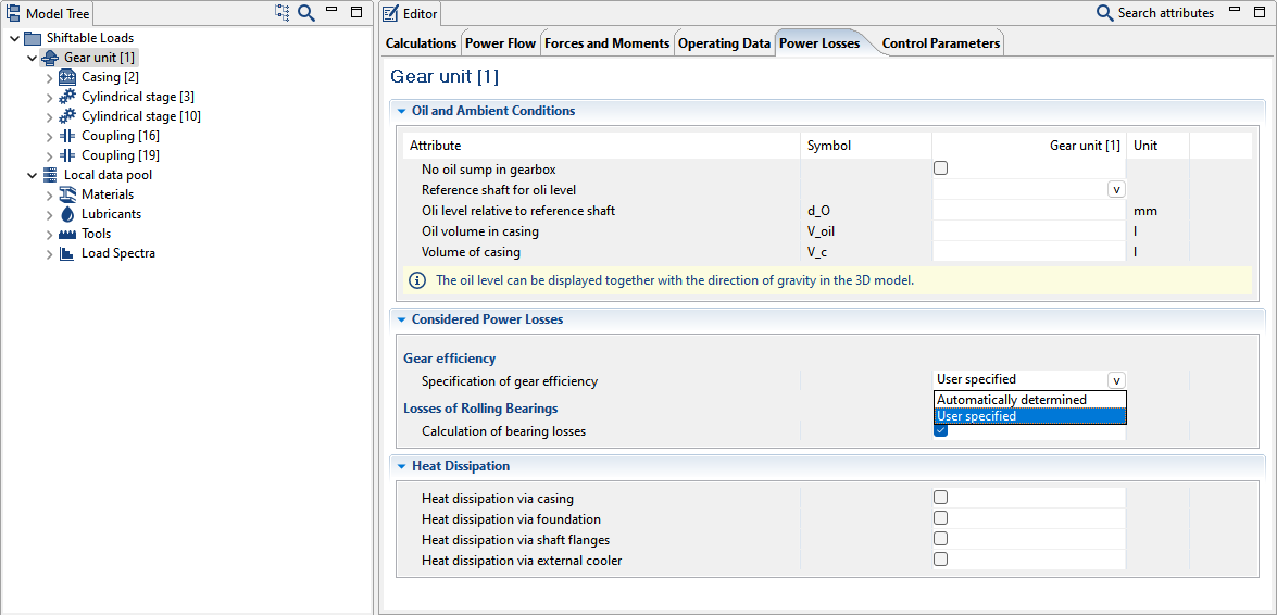
The efficiency of gear stages can now also be user-specified.
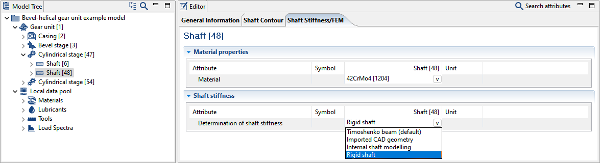
Shafts and wheel bodies can now be toggled as stiff in the system calculation.
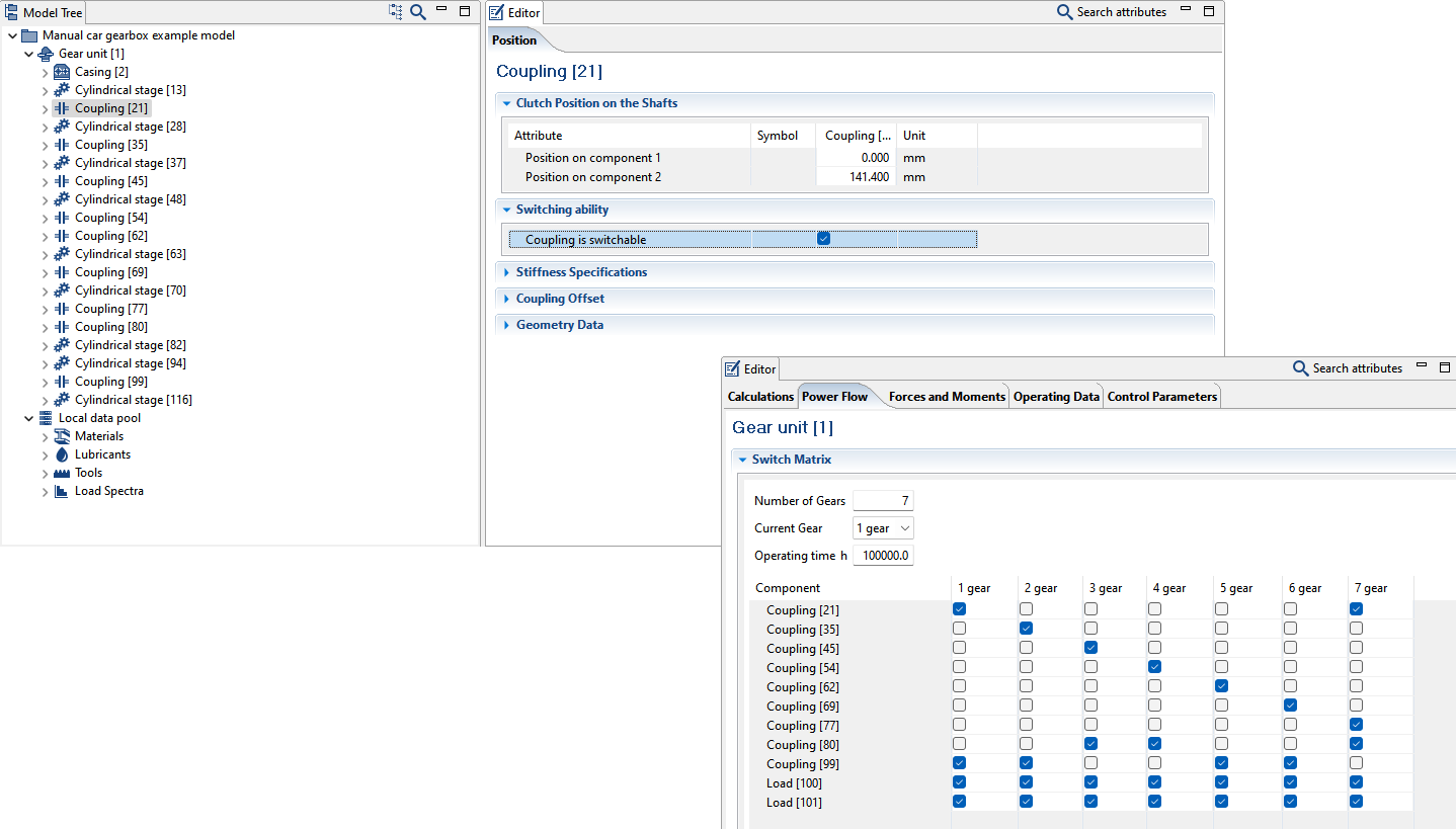
Up to this point, couplings and loads have always been switchable. However, they can now optionally be made non-switchable in the Editor and are then no longer shown in the switching matrix. This increases clarity, especially in complex gear units.
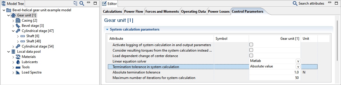
The maximum number of iterations to be performed in the system can now be configured. Additionally, a force or torque can be specified as a termination threshold. The system iteration will be performed until the absolute differences in the calculated forces and moments are below the termination threshold from one iteration step to the next. Relative percentage specification of the termination threshold is also possible.
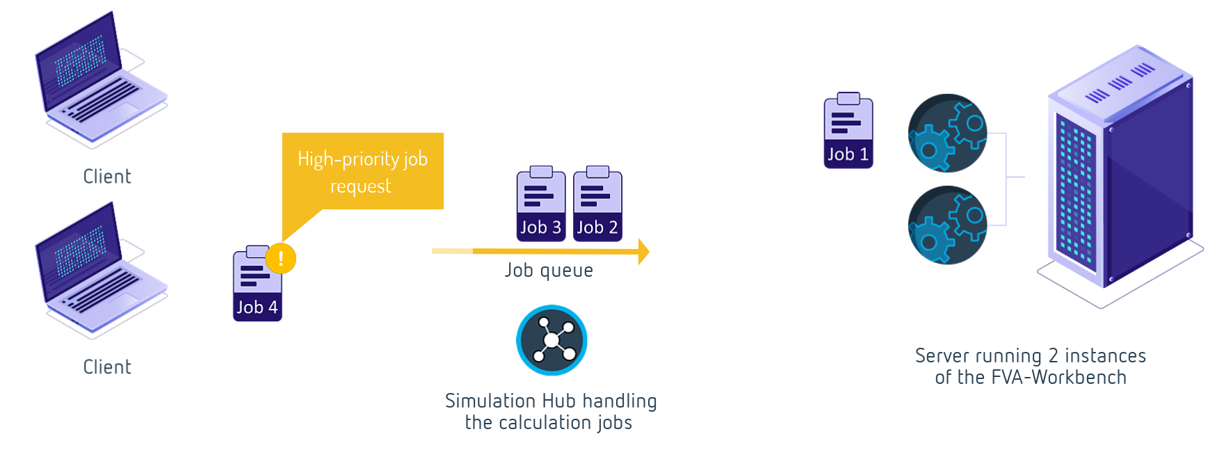
The FVA Simulation Hub is an independent application from the FVA-Workbench which can be operated as a service on a server. Any number of clients can send calculation tasks (jobs) to the Simulation Hub using so-called requests. The Simulation Hub distributes the jobs among multiple instances of the FVA-Workbench. The calculation results are returned to the client as a response.
Cylindrical gears
Output of the addendum and dedendum of the finished gear (addendum_height_finished_gear, dedendum_height_finished_gear)
Specification of the protuberance for the gear reference profile and geometry
Calculation of the circumferential backlash at the pitch circle (maximum_transverse_backlash_pitch_circle, minimum_transverse_backlash_pitch_circle)
Design calculation according to VDI 2736 is now possible for plastic-steel combinations
Modification of the identifiers for permissible stresses for ISO 6336, DIN 3990, and VDI 2736 load capacity methods
Bevel gears
Integration of KNplus version 5.0.1
Integration of BECAL version 6.2.5
Bevel gear standard calculations: tolerances acc. to ISO 17485 can be applied for displacements and deviations
Improved operation of the boundary editor when importing bevel gears
New outputs for transverse, overlap, and total contact ratios acc. to ISO 10300 (2014)
Calculation of the local circumferential backlash is now a fixed part of the extended gear calculation and does not need to be activated
Uniform relative immersion depth for BECAL and KNPLUS
KIMoS 3D neutral data file names can now be in p*o___nd.dat, g*o___nd.dat, p_o___nm.dat, g_o___nm.dat format. "*" stands for the processing state ("r," "b," "g," "f," "a," "l"), or "_" if it is not named
Bearings
The roller cone angle can now be considered for spherical roller thrust bearings
The effective rolling element length can now be specified or internally estimated for the "internal geometry" and "XML bearing" rolling bearing input types
Bearing coefficient determined based on the bearing series for ISO 14179 friction calculation
Additional options for determining the viscosity ratio kappa for modified bearing life calculations
Solid friction coefficient according to FVA 365 VII can now be considered in the SKF friction calculation
Axial plain bearing calculation can now be performed for a single segment following the system calculation
Shafts & shaft-hub connections
Angular position of the FE component can now be specified for analysis of the variable stiffness about the circumference for FE shafts
"Conical shaft shoulder" notch shape can now be calculated using FKM
Revision of feather key calculation according to DIN 6885 and DIN 6892
The shaft diameter in the center of the feather key is now used to determine the width and height of the feather key according to the standard as well as for the DIN 6892 calculation
Press fit sliding safety now calculated according to FVA 312
Adjustment of the clearance calculation for spline connections
Additional
REXS version 1.5 format is now supported
REXS files can now be exported with JSON file format with .rexsj extension
The load sharing factor K_gamma is now only shown when calculations are performed using nominal torques, not with the load distribution from the system calculation
As with other fields in the input editor, mathematical operations can now be performed in the "operating time" field in the power flow editor
External stiffness matrices from Abaqus MTX files can now be used for casings and planet carriers
Report configurator performance has been significantly improved, especially when adding and deleting charts or tables
New "model" section for displaying project-specific data in reporting
Bugfixes
Bugfix: consideration of the load-dependent center distance in subsequent calculations
Bugfix: tolerance comparison (STplus)
Bugfix: form factor in VDI 2736 corrected
Bugfix: value transfer from RINA calculation
Bugfix: calculation of the circumferential backlash corrected
Bugfix: warning if a tool with a full tip fillet is transferred to STplus
Bugfix: positioning of seals between two shafts in bevel gearboxes
Bugfix: import for connected bevel gear stages via a common bevel gear
Bugfix: contradictory specifications of depth crowning in the standard calculation
Bugfix: DNV/GL load capacity
Bugfix: Woehler S-N curves for FVA 411
Bugfix: adjustment of the modified reference life (ISO/TS 16281) for multi-row roller bearings
Bugfix: improved stability of the system solver when ovalization is specified
Bugfix: bearing selection from catalog
Bugfix: calculation of bearing clearance without inner/outer ring
Bugfix: determination of tilting moments with tapered rolling elements
Bugfix: improved estimation of roller angles for tapered roller bearings
Bugfix: calculation of the contamination coefficient e_C in load spectrum
Bugfix: conversion of the axial clearance of rolling bearings
Bugfix: convergence problems with lightly loaded bearings with clearance when using the SKF Calculation Service
Bugfix: axial force stress curve for DIN743
Bugfix: improved determination of the load distribution factor K_Lambda of feather keys
Bugfix: torsion angle when using FE shafts
Bugfix: cross-section calculation with cross-bore notch shape
Bugfix: bending moment load of splines
Bugfix: negative mean stress for tension/compression leads to incorrect impact factor (DIN 743)
Bugfix: modeling of single-plate planetary stages
Bugfix: display of couplings in the switching matrix of planetary stages
Bugfix: add planetary stage wizard (use case: double-plate planet carrier with speed reduction)
Bugfix: add cylindrical stage wizard (use case: both gears added to existing shafts)
Bugfix: wheel body disappears from 3D model after calculation
Bugfix: specification of the immersion depth of planetary stages
Bugfix: additional consistency check for REXS export of flank modifications
Bugfix: FEM deformation calculation when 3D view is closed
Bugfix: disabled license expiration warning in batch mode
Bugfix: calculation of worm losses acc. to FVA 729