Gear corrections (modifications)
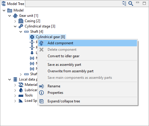
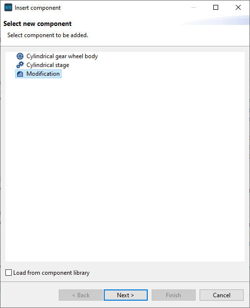
In the FVA-Workbench, gear modifications are components that can be added to cylindrical gears. Multiple modification forms (such as helix angle and profile modifications) can be defined for each modification component.
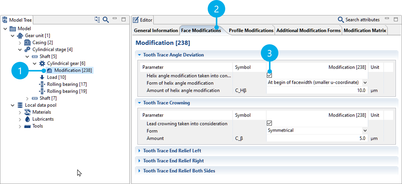
(1) Gear modifications are added as components on cylindrical gears.
(2) The different types of modifications are divided into several tabs.
(3) Whether a modification form should be considered can be activated and deactivated.
If multiple modification types are specified, they are applied additively in the FVA-Workbench.
Definition range
The definition range determines the positions at which the respective amount of a modification is specified. There are three options for setting the definition range.
Entire field of action
The definition range corresponds to the entire field of action. No further specifications are necessary.
Specify the same definition range for all modifications
The definition range can be defined via the parameters ab,l, ab,r, dBa, and dB,f. All modifications refer to this specified definition range.
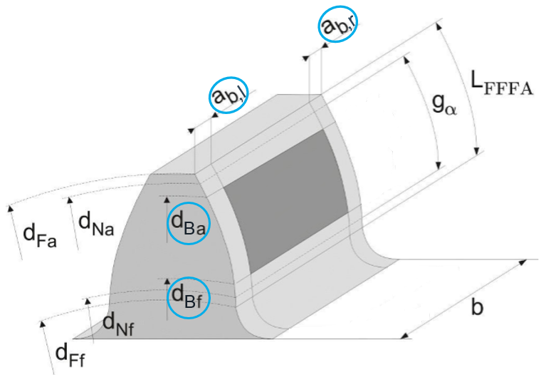
dBa tip reference diameter
dBf root reference diameter
ab,l definition range indentation, left
ab,r definition range indentation, right
Specify definition range individually for each modification
Optionally, the definition range can be specified separately for each modification. Depending on the type of modification, different parameters must be specified to uniquely define the definition range.
Evaluation range
The evaluation range can be used to specify the area of the flank in which the modification is to be evaluated. This does not influence the calculation; however, the corresponding diagrams in the output report are cropped to the evaluation range.
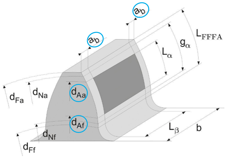
dAa tip evaluation range
dAb root evaluation range
ab evaluation range indentation
Face modifications
Helix angle modification
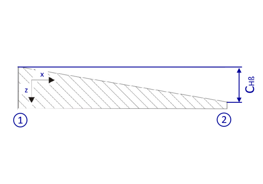
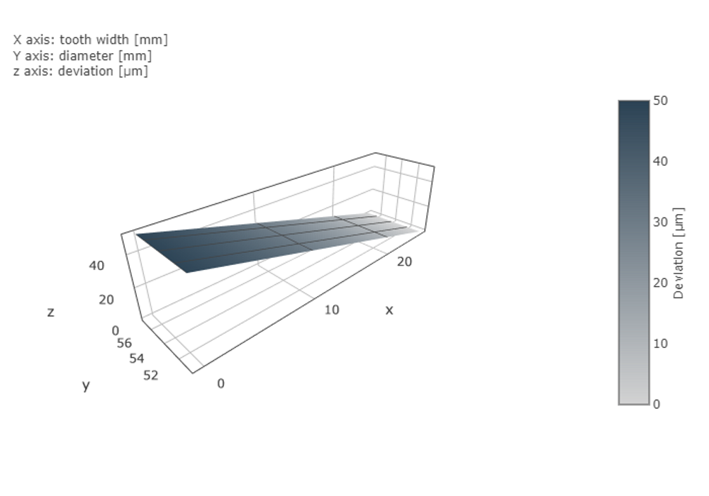
Helix angle modification with a modification amount CHβ of 50 µm.
(1) left
(2) right
Face crowning
In addition to symmetrical, the following modification forms can be specified:
Asymmetrical
2 asymmetric circular arcs
Parabolic
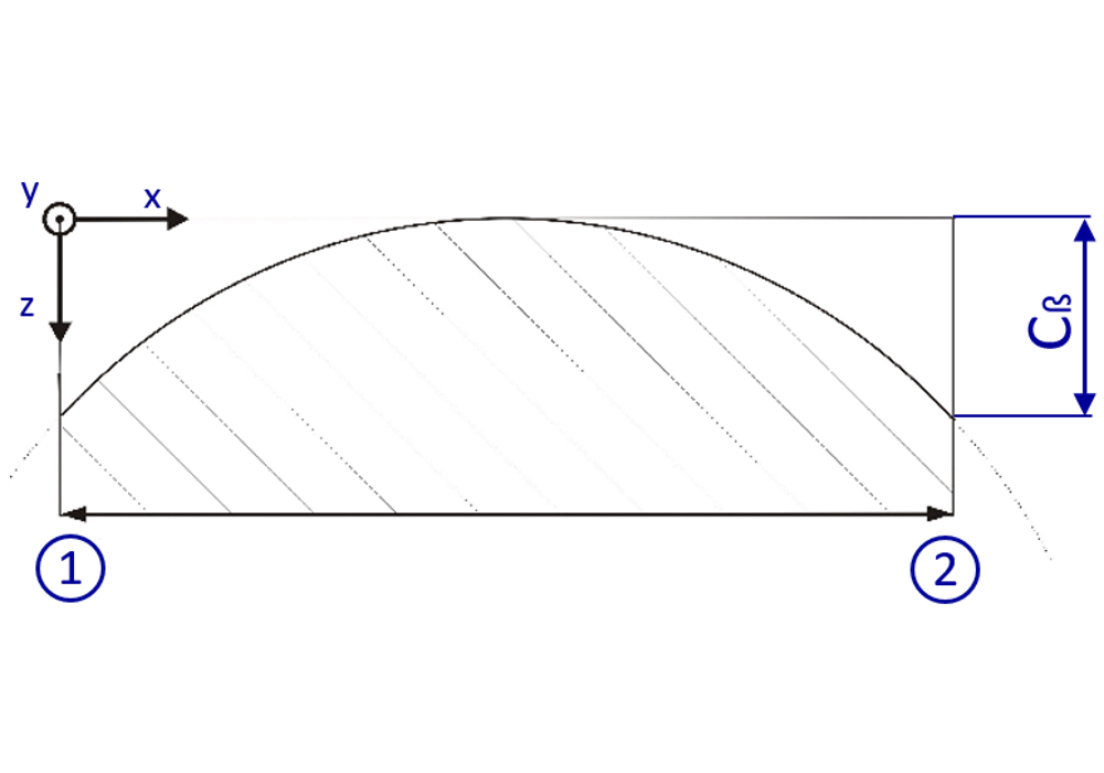
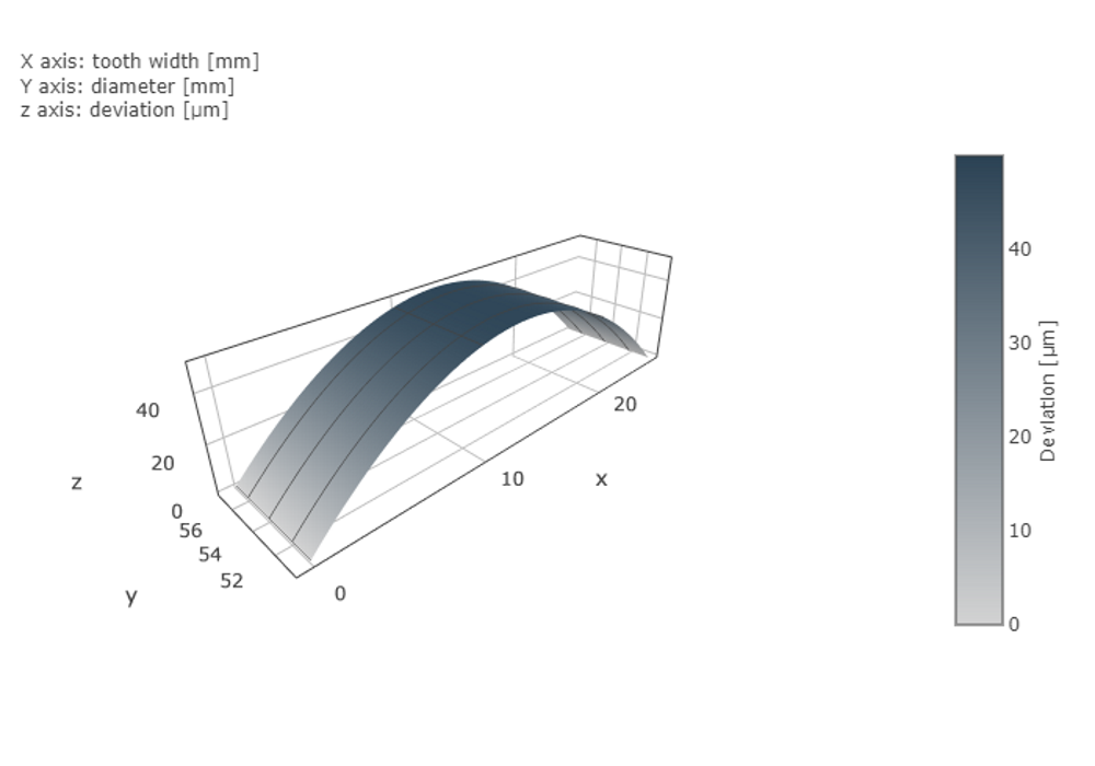
Symmetric crowning with a modification amount Cβ of 50μm.
(1) left
(2) right
End relief
In addition to linear end relief with radial transition, the following modification forms can be specified:
Linear without radial transition
Circular
Polynomial
Exponential
Logarithmic
It is also possible to specify different modification forms on the left and right.
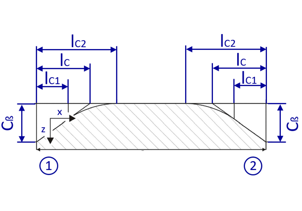
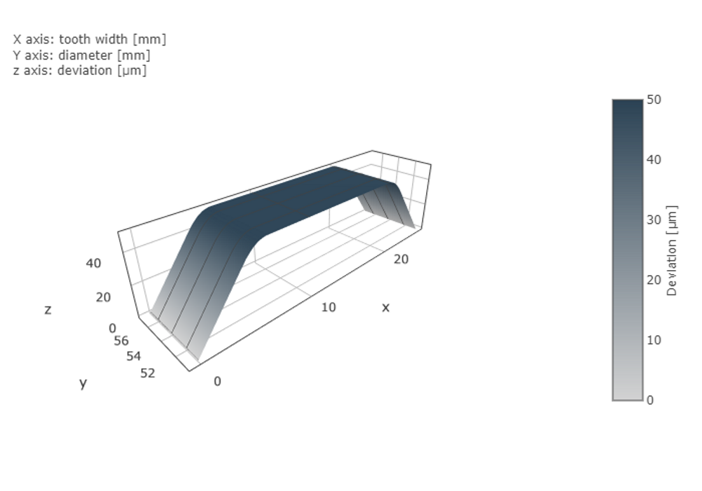
Linear end relief left and right with radial transition. Amount of end relief Cβ of 50 µm over a modification length lC of 5mm.
The radial transition starts at lC1 = 4mm and ends at lC2 = 6mm.
(1) left
(2) right
Profile modifications
Profile crowning
In addition to symmetrical profile crowning (relative to the path of contact), the following modification forms can be specified:
Asymmetric al
2 asymmetric circular arcs
Parabolic
Symmetrical (relative to the diameter)
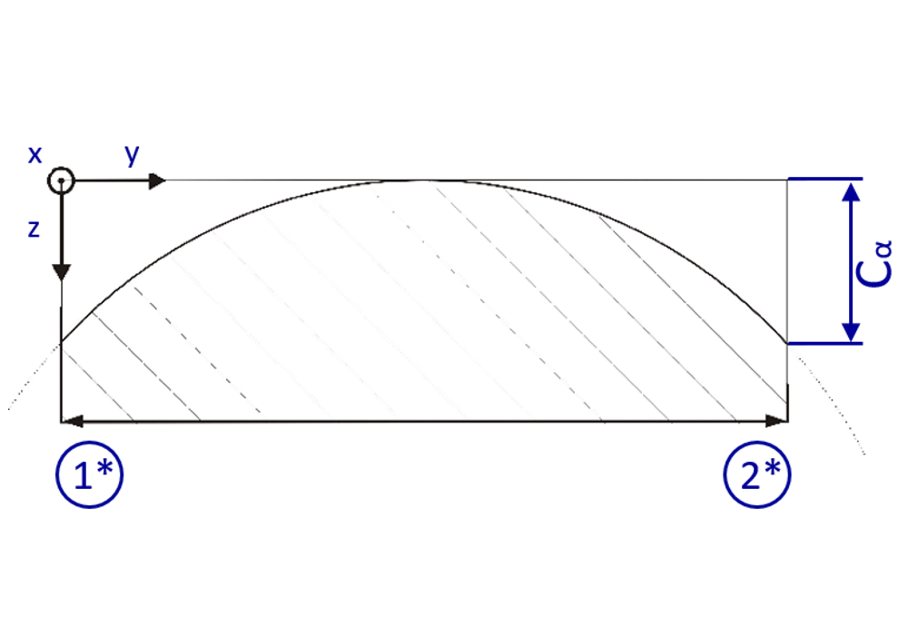
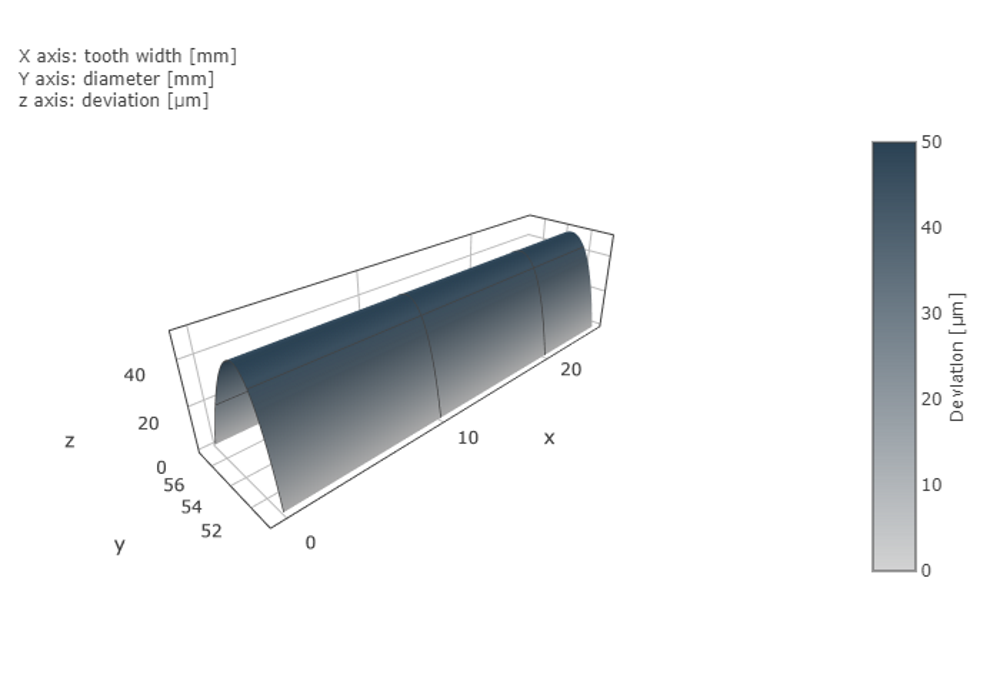
Symmetric profile crowning (relative to the path of contact) with a modification amount Cα of 50µm.
(1*) Root
(2*) Tip
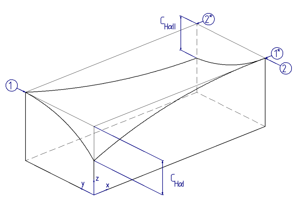
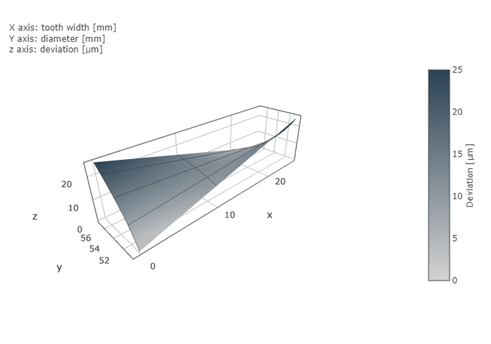
Profile angle modification
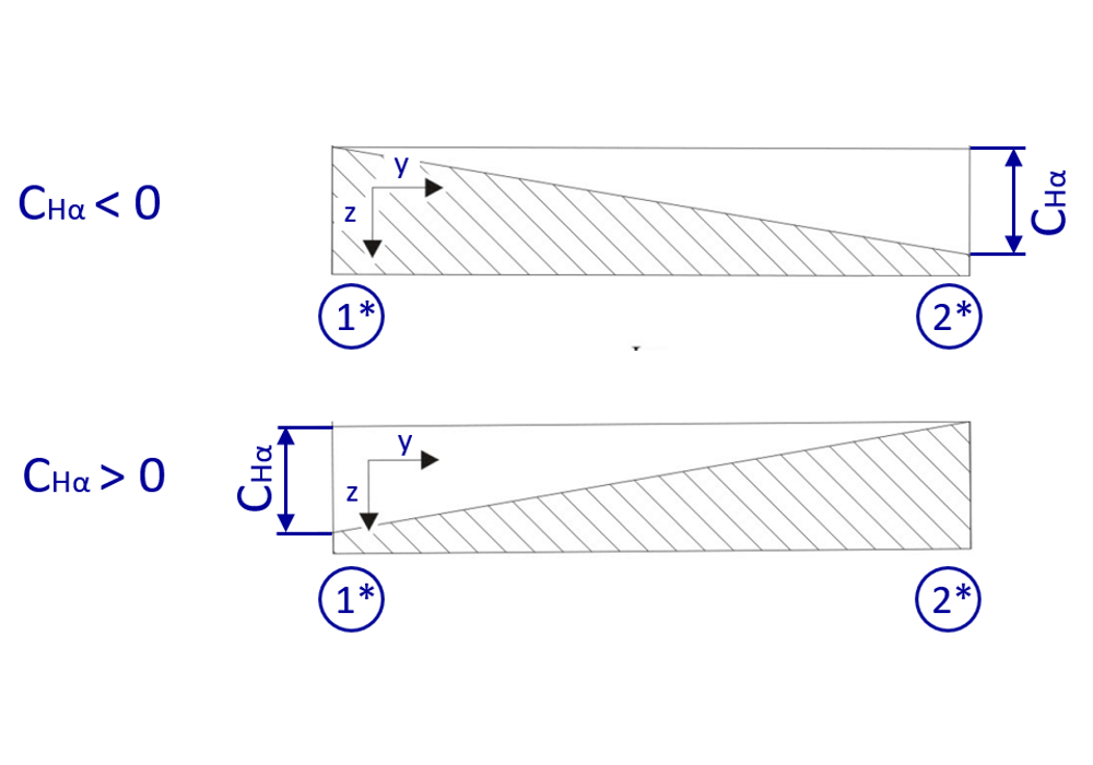
Profile angle modification with a modification amount CHα of 50µm.
(1*) Root
(2*) Tip
Tip and root relief
In addition to linear tip relief, the following modification forms can be specified:
Circular
Polynomial
Exponential
Logarithmic
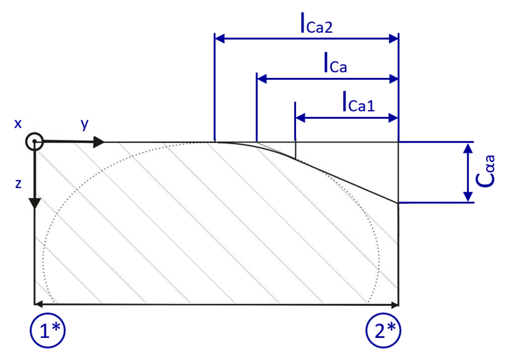
Linear tip relief with radial transition. Amount of tip relief Cαa of 50 µm over a modification length lCa of 5mm. The radial transition starts at lCa1 = 4 mm and ends at lCa2 = 6 mm.
(1*) Root
(2*) Tip
Additional modification forms
Rolled modifications (triangular end relief)
In addition to linear triangular end relief, the following modification forms can be specified:
Circular
Polynomial
Exponential
Logarithmic
In addition to triangular relief to the root, the same modification forms can be specified for the tip.
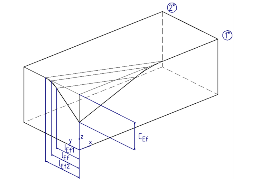
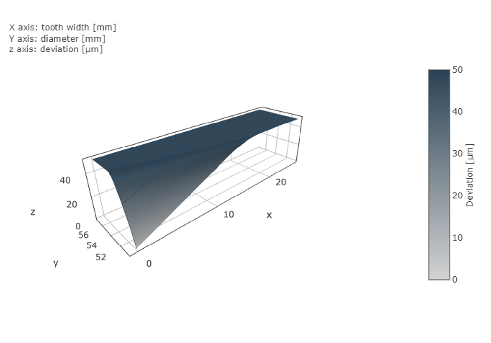
Linear triangular end relief to the root with radial transition. Modification amount CEf of 50 µm over a modification length lEf of 5mm.
The radial transition starts at lEf1 = 4mm and ends at lEf2 = 6mm.
(1*) Root
(2*) Tip
Twisting
Twisting is a modification to the tooth flank in which the transverse profile is continuously rotated along the flank line to the non-modified involute screw surface. It corresponds to the opposite profile angle modifications on the reference and non-reference side of the flank.
Twisting with a modification amount |Sα| = CHαI + CHαII of 50 µm.
(1) Left
(2) Right
(1*) Root
(2*) Tip
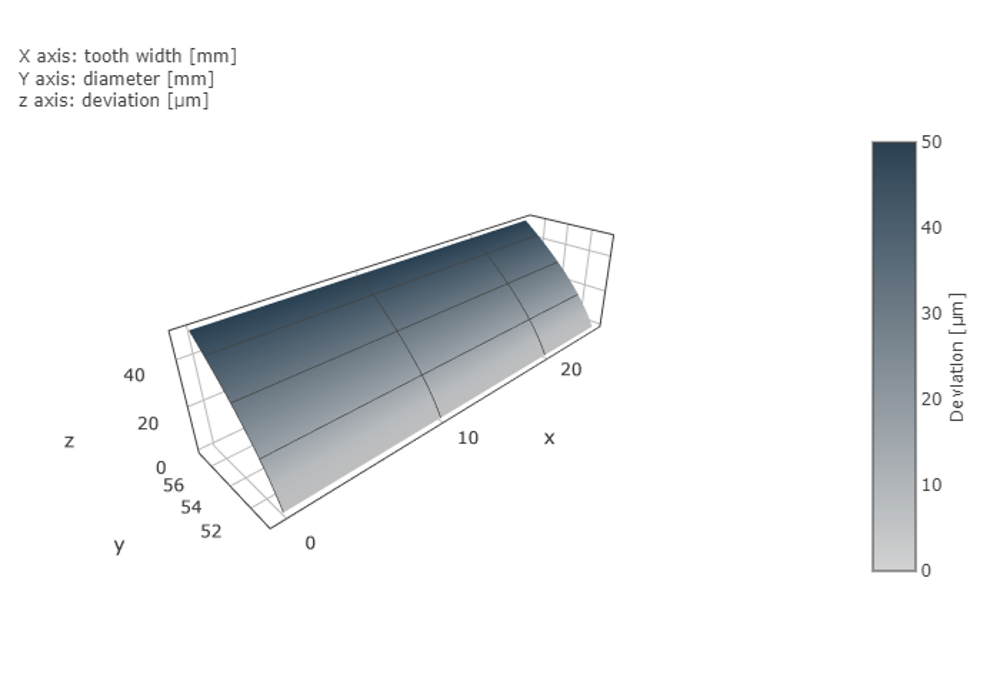
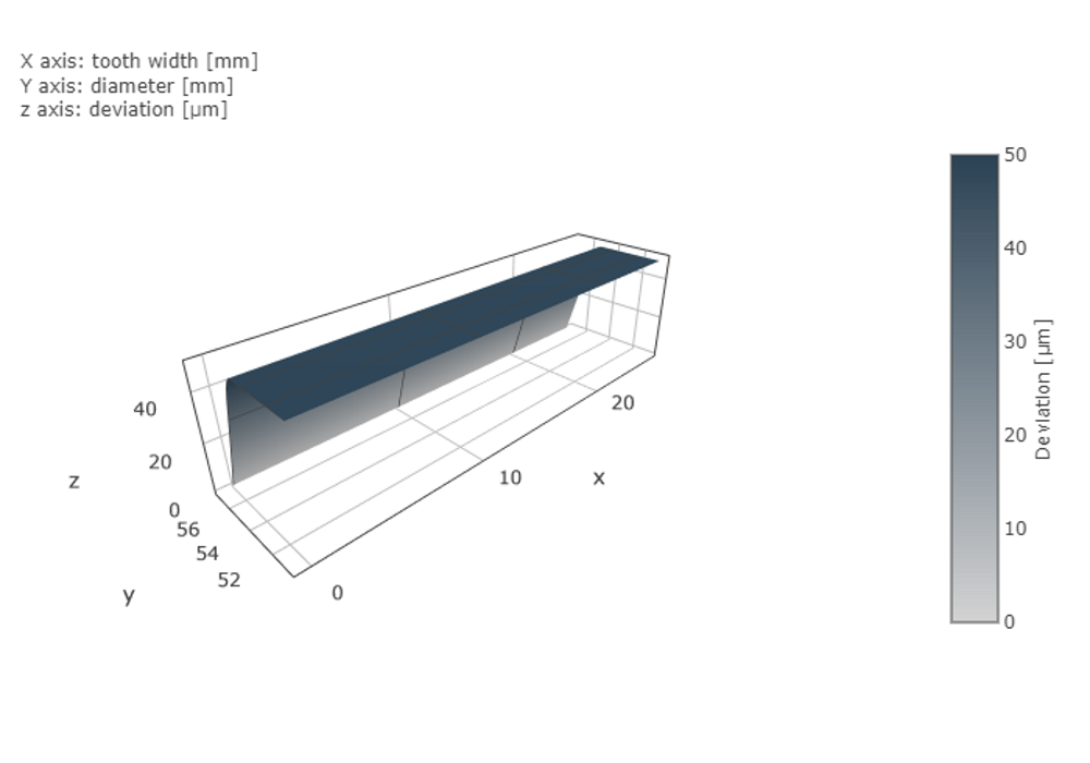
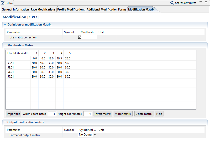
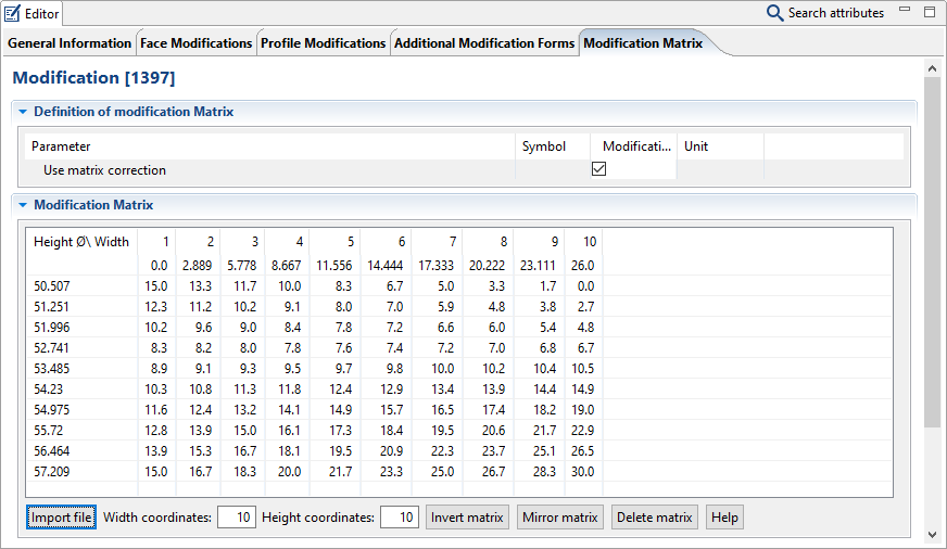
Modification matrix
The modification matrix makes it possible to specify local modification amounts for the flanks of a gear. Modifications are specified via the modification amount in µm; the height and width coordinates are specified in mm. Any number of width and height support points can be defined for the matrix.
Positive modification amounts correspond to removal of material from the flank. As the modification amounts are negative in the measurement data, they are inverted when importing. Modification amounts in modification matrices are applied additively to the standard modification amounts.
The width coordinates are specified in the first line of the Editor in mm relative to the left face of the corresponding gear. The height coordinates are specified in the first column of the Editor in mm as diameter specifications for the corresponding gear (from top to bottom in ascending order).
In addition to manual specification, modification matrices can be imported in the following formats:
ZF format
GDE format
TOP format
MKA format
CSV format
The following formats can be exported:
ZF format
TOP format
CSV format
Notice
Specifying modification matrices via Scripting
To automatically transfer the modification matrix via Scripting, the following attributes of a modification component can be set using setAttr():
Attribute name | Attribute ID | Description |
|---|---|---|
Consider modification matrix | sekor_matrixk_enabled | Switch for whether or not a modification matrix should be considered. |
Profile coordinates (mm) | width_coordinates | Array in which the coordinates in the width direction (face width) are stored. |
Height coordinates (mm) | height_coordinates | Array in which the coordinates in the height direction (diameter) are stored. |
Modification matrix (µm) | modification_matrix | Matrix in which the modification amounts are stored. The matrix dimensions result from the profile coordinates x height coordinates. |
Importing matrices
Modification matrices can be imported in the following formats:
ZF format
TOP format
CSV format
MKA format
GDE format
After the import, the modification matrix appears in the Editor and can be considered.
Notice
If the "consider modification matrix" option is selected, the modification matrix will be applied additively with any other modifications.
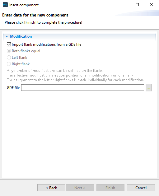
Importing GDE files
The import process for GDE files is different from other file formats. If a new modification component is added to a cylindrical gear, the option for "import flank modifications from a GDE file" can be selected.
 |  |  |
Exporting matrices
The flank modification specified for the calculation can be exported in the following formats:
ZF format
TOP format
CSV format
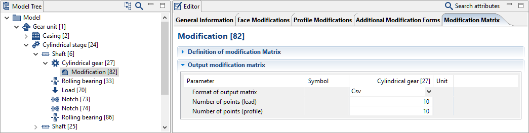
To export the flank modifications, the format and the number of interpolation points in the width and profile directions must be specified.
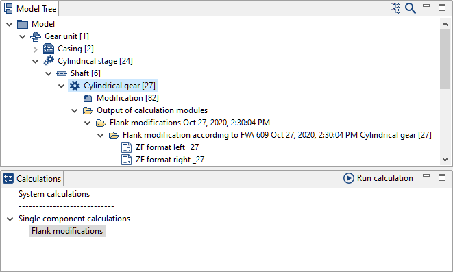
To start the export, select the relevant gear in the Model Tree and run the "flank modifications" calculation.
The exported matrix will be displayed separately for the right and left flanks under the cylindrical gear in the Model Tree.
Notice
If no directory structure is shown under the cylindrical gear after the calculation, the "show kernel output files" feature must be activated in the settings.
Settings -> Calculation kernel outputs:
☑ Show kernel output files
☑ Save results in a sub-folder
Formats
The following examples demonstrate the structure of the supported file formats.
CSV format
(1) Width coordinate, relative to the left end face
(2) Diameter
(3) Modification amount
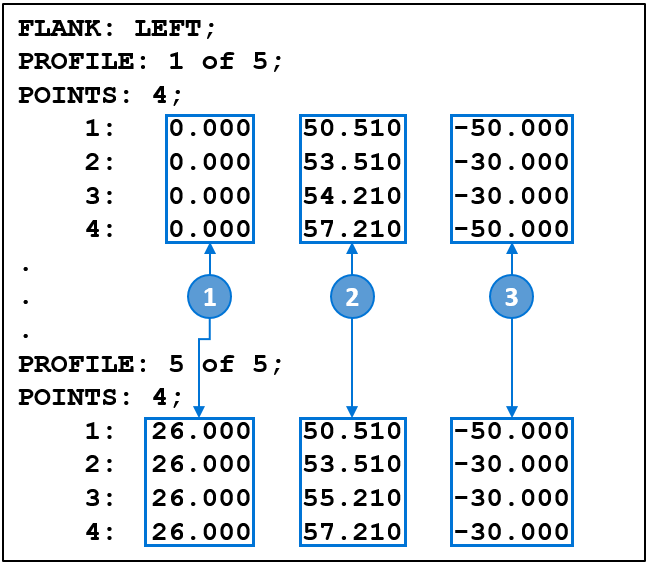
TOP format
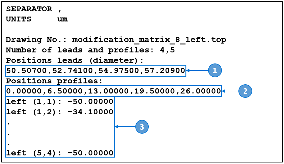
(1) Diameter
(2) Width coordinate, relative to the left end face
(3) Modification amount
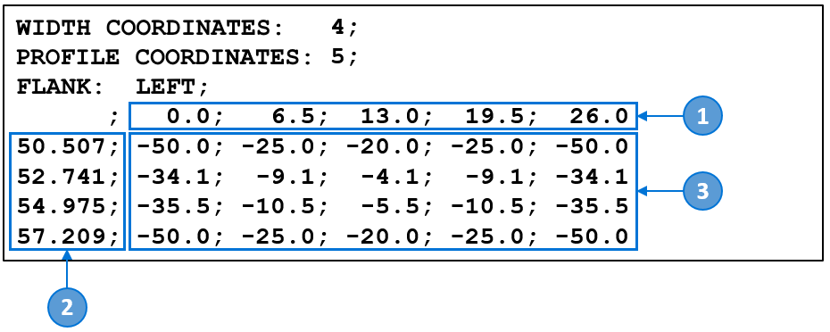
ZF format
(1) Width coordinate, relative to the left end face
(2) Diameter
(3) Modification amount