Bevel Gear Measurement Data Processing
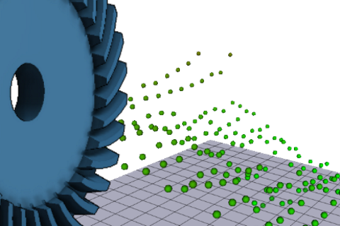
This tutorial will demonstrate the import and processing of exact bevel gear flank geometries as 3D measurement data. These point clouds can then be considered in the advanced gear calculations.
The following files are needed to follow along with this tutorial in the FVA-Workbench:
Example actual and nominal measurement data files
This archive contains the following files:
File name | Type |
|---|---|
Standard.KGD | Machine settings |
actual_measurement_data_left_flank_pinion.DAT | Actual measurement data for left flank - pinion |
actual_measurement_data_left_flank_wheel.DAT | Actual measurement data for left flank - crown gear |
nominal_measurement_data_left_flank_pinion.DAT | Nominal measurement data for left flank - pinion |
nominal_measurement_data_left_flank_wheel.DAT | Nominal measurement data for left flank - crown gear |
Modeling the bevel gear stage
Create a new model
 (Project → New)
Add a bevel gear stage
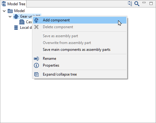
Right-click the Gear Unit in the Model Tree and add a bevel gear stage component.
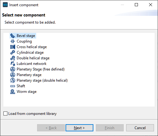
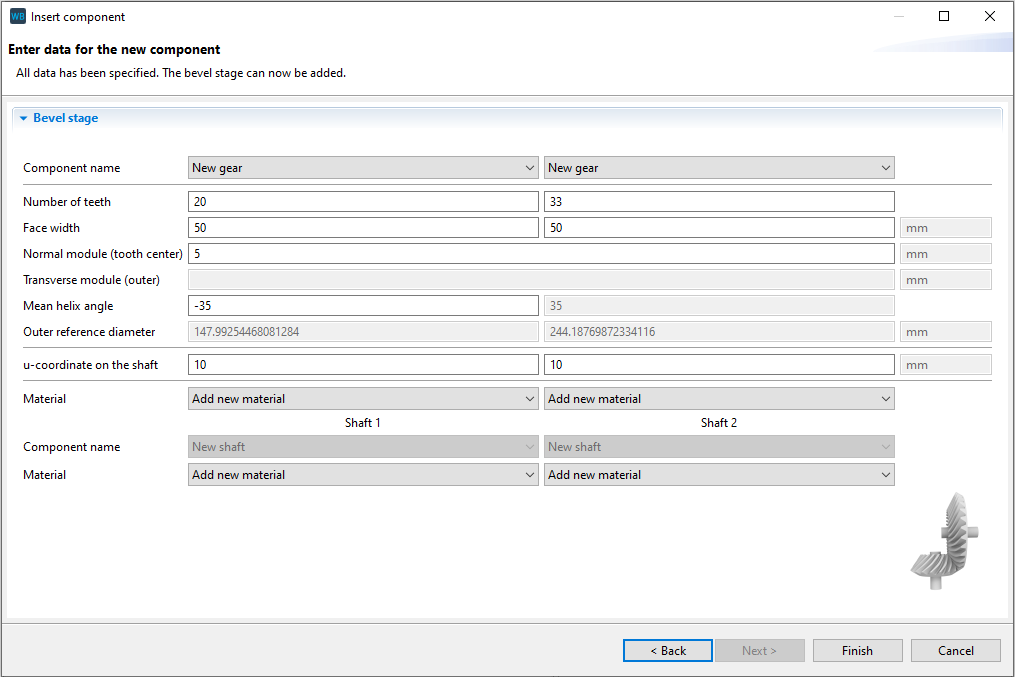
Specify the gear data
Click Finish (do not make any changes to the gear data).
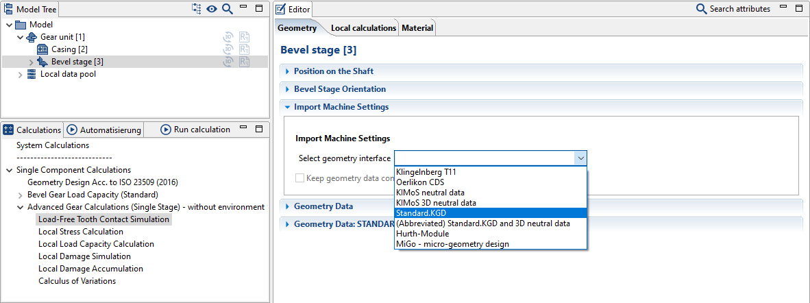
Import the Standard.KGD file
The geometry data for the bevel gear is specified by importing the Standard.KGD file. Standard.KGD is a simple interface for the calculation of bevel gears and includes all necessary information for the manufacturing simulation and generating the nominal geometry.
Select Standard.KGD in the drop-down menu and specify the path to the directory where the file is located.
Importing and processing the measurement data
Activate specification of actual measurement data
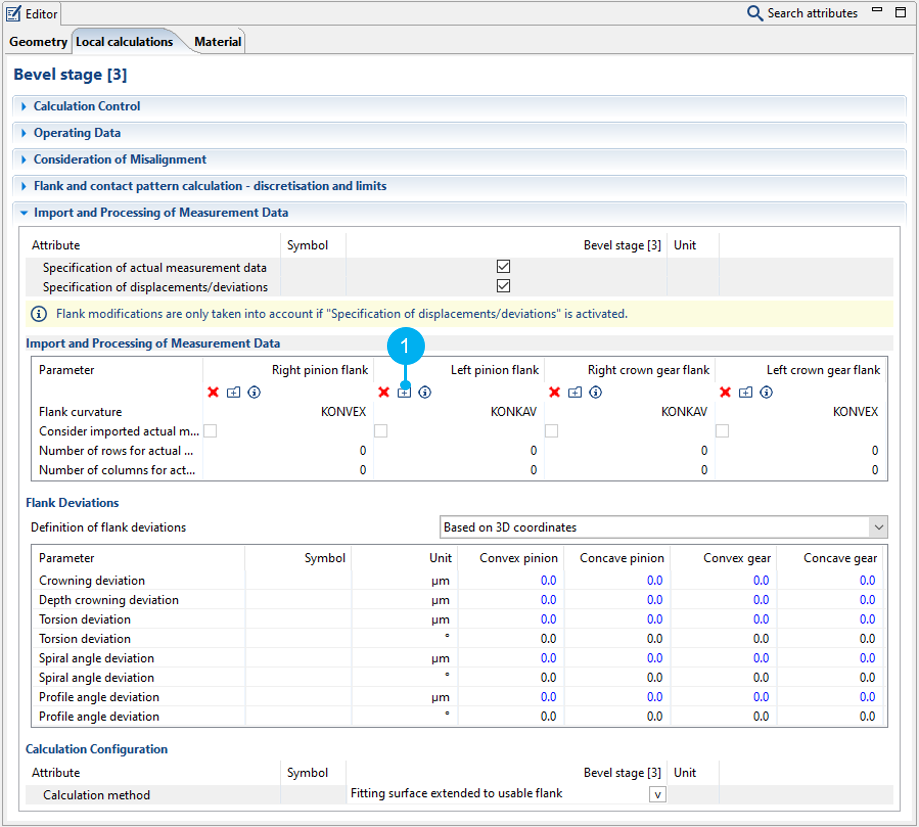
Select "Bevel stage [3]" in the Model Tree and select one of the advanced gear calculations in the "calculations" view. Select the tickbox for "specification of actual measurement data" in the Editor, as shown in the image below. A new "actual measurement data" tab will now be shown.
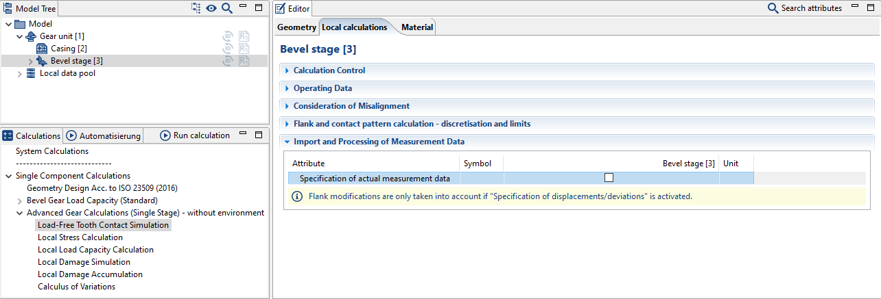
This expands the view in the editor for entering the measurement data.
Import the measurement data
Switch to the "actual measurement data" tab. The nominal and actual measurement data for the right and left flank of the gear and pinion can be imported separately here.
Click (1) to import the measurement data for the left flank of the pinion.
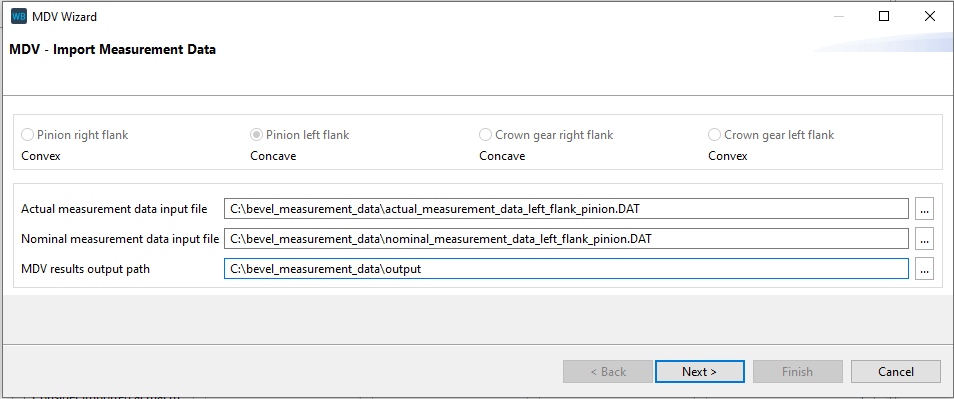
Specify the paths to the actual and nominal measurement data files as well as an output path.
actual_measurement_data_left_flank_pinion.DAT
nominal_measurement_data_left_flank_pinion.DAT
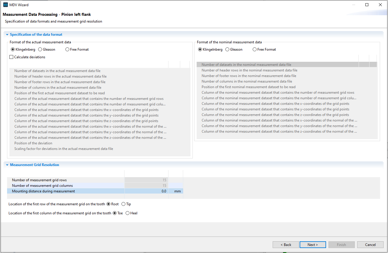
Select a format
The example measurement data is in Klingelnberg format. Select this format for the actual and nominal measurement data. Enter 0 mm for the "mounting distance during measurement." The mounting distance can be used to specify an additional axial offset between the bevel cone tips and the coordinate origin.
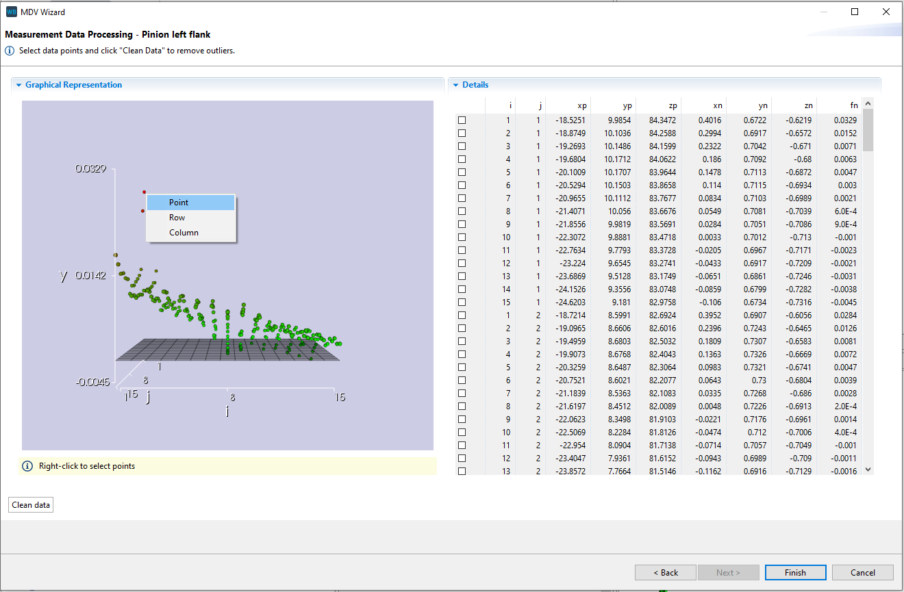
Selecting outliers
Outliers can be selected from the graphic and tabular representations of the measurement data in the next step. Right-click in the graph or select individual points, columns, or rows in the table. Click "clean data" to remove the points from the actual measurement data.
Calculation
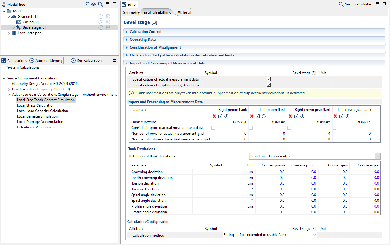
Activate consideration of the measurement data in the calculation
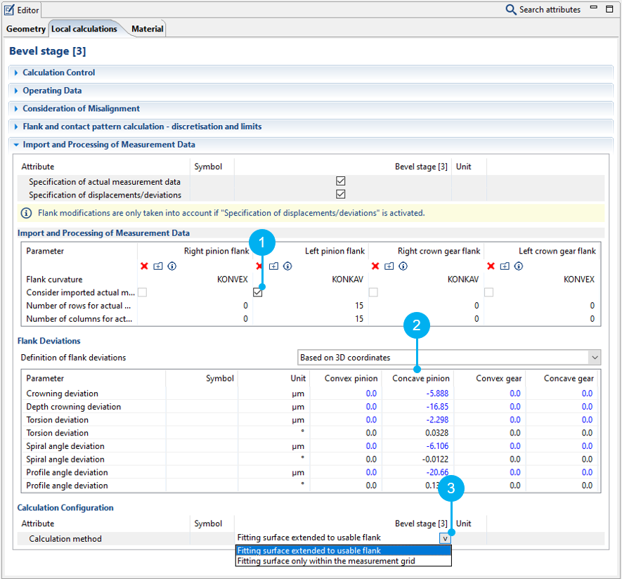
Set the tickbox (1) so that the imported measurement data can be considered for the advanced gear calculations. If this tickbox is not selected, only the calculated flank deviations (2) will be used in the calculation.
The calculation method (3) specifies whether the local calculation is carried out only within the measuring grid (fitting surface only within the measuring grid) or on the entire usable flank (fitting surface extended to the usable flank).
This example only shows the process for the left pinion flank.