Calculating the power flow
At least two load components must be present on one or more shafts to successfully calculate the power flow.
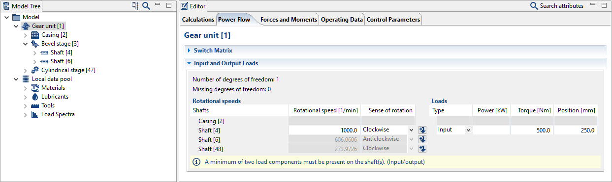
Shaft load components can be created and configured in the Power Flow Editor.
The type of torque application on the shaft can be defined for each load component using the following options:
No torque application - the load is deactivated
Input - power is applied
Output - power is transferred
Clockwise - a clockwise-rotating torque is applied, regardless of the direction of rotation of the shaft
Anti-clockwise - an anti-clockwise rotating torque is applied, regardless of the direction of rotation of the shaft
Torque calculation
Possible actions for under-determined torque:
Deactivate an undetermined load (type -> "none")
Specify torque/power for an undetermined load
Deactivate the coupling to the casing
Possible actions for over-determined torque:
Add an undefined load (type -> "input/output/anti-clockwise/clockwise")
Remove torque/power for a load
Add a coupling to the casing
Add a connection between two existing shafts (stage, coupling, etc.)
Switchable loads
The power flow can only be calculated for a coherent power path. It must contain at least two load components, including at least one input and one output. To enable the specification of different loads per gear, the following check is performed prior to the power flow calculation:
First, all connected power paths are determined (i.e., independent of the switching of the coupling).
The number of loads included in each of these power paths is then determined. If there is exactly one path with at least two loads, it is assumed that this is the power flow to be calculated. Power paths that go nowhere (include only input or output) are ignored.
If there are several connected power flows, the algorithm cannot conclusively determine the power path. Therefore, the user must adjust the specified loads.
Notice
The Modeling a Shiftable Gearbox tutorial demonstrates the modeling of a gearbox with switchable loads.
Torque splitting
By default, uniform power distribution is assumed for power circuits (power branching and merging).
If the "Consider resulting torques from the system calculation instead of nominal torques" switch is activated, the actual power splitting (independent of the stiffness of the gearbox) is automatically determined and considered for further calculations.
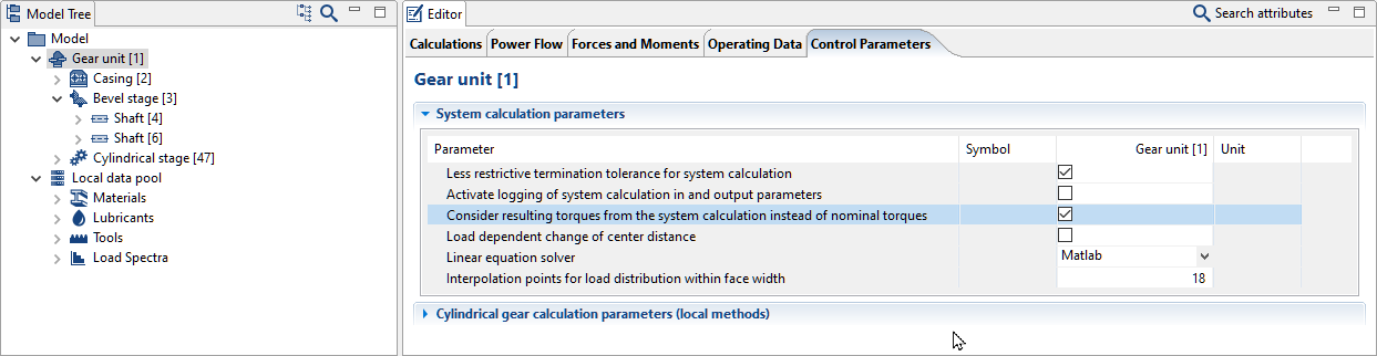
If the "Consider resulting torques from the system calculation instead of nominal torques" switch is activated, the actual power distribution is used for all further calculations in the system.
Notice
The Power Splitting tutorial demonstrates the design of a gearbox with power splitting.