Rolling bearing calculations
Bearings make unrestricted relative rotational movements between machine elements possible. In rolling bearings, rolling elements (balls, rollers, needles) separate the running surfaces of two moving components from each other. Since the rolling elements roll along the raceways, rolling friction resistance is low. Lubricants reduce bearing friction (which leads to losses in the gear unit).
Depending on the type of rolling elements, rolling bearings are divided into ball bearings and roller bearings (needles are seen as thin rollers). Furthermore, a distinction is made between radial and axial bearings, based on the main load. The following bearing types are supported in the FVA-Workbench:
Radial bearings | Axial (thrust) bearings | |
|---|---|---|
Ball bearings |
|
|
Roller bearings |
|
|
Several different levels of detail are available for modeling rolling bearings:
Bearing stiffness: The bearing is considered only as a linear stiffness element in the mechanical system
Catalog bearings: Selection of a rolling bearing from the catalog of the desired manufacturer (Schaeffler, SKF, Timken). All relevant catalog data is completed automatically. The internal geometry of the bearing (number of rolling elements, rolling element diameter, etc.) is estimated in the calculation process.
Specification of the main geometry: If special designs or catalog bearings from a different manufacturer are used and more precise information about the bearing inner geometry is not available, the catalog data can also be entered manually. The internal geometry of the bearing (number of rolling elements, rolling element diameter, etc.) is estimated in the calculation process.
Specification of the internal bearing geometry: Detailed information on the inner geometry of the bearing can be specified, if available.
Specification of a bearing manufacturer's xml file: This includes information on the internal bearing geometry, and may be available from the bearing manufacturer upon request.
Selection of an "FVA catalog bearing:" As part of FVA 364 II, a rolling bearing database was created that includes the (current at the time) SKF and Schaeffler catalog data as well as estimated internal bearing geometry data.
Overview of symbols
Symbol | Description |
|---|---|
B | Bearing width |
bm | Load rating coefficient for bearings according to ISO 281 |
Cor | Static load rating |
Cr | Dynamic load rating |
d | Bearing inner diameter |
D | Bearing outer diameter |
dbore | Inner diameter of the bore (usually of the casing) |
DG | Equivalent diameter of the casing |
Dpw | Reference diameter |
dR | Distance between the bearing rows (distance of the midpoints of the rolling elements of both bearing rows) |
dshaft | Outer diameter of the shaft (or pins/casing journals) |
DW | Rolling element diameter |
E | Outer ring raceway diameter |
Em | Modulus of elasticity |
E(κ) | Elliptic integral of the second kind |
F | Inner ring raceway diameter |
f0 | Factor for calculation of the static load rating according to ISO 76 |
Fa | Axial force |
fc | Factor for calculation of the dynamic load rating according to ISO 281 |
fi, fa | Curvature ratio between the inner or outer ring raceway and the rolling element |
Fr | Radial force |
Fu,Fv,Fw,Mv,Mw | Resulting bearing force in the u/v/w-direction, or resulting tilting moment about the v/w-axis |
gF | Roughness smoothing factor according to DIN 7190 |
i | Number of bearing rows |
Ii,eff | Effective interference between shaft and inner bearing ring |
L | Roller length |
le,eff | Effective interference between outer bearing ring and bore (of the casing, etc.) |
LWE | Effective roller length |
M | Distance from the center of the radius of curvature to the inner/outer raceways |
Me | Center of the radius of curvature of the outer ring raceway |
Mi | Center of the radius of curvature of the inner ring raceway |
Re, Ri | Distance from the center of the radius of curvature of the inner/outer ring raceway to the shaft axis |
ri, re | Radius of the raceway on the inner/outer ring |
Rp | Spherical roller outer radius |
Rz | Average roughness depth |
sa | Axial operating clearance |
sr | Radial operating clearance |
sα | Operating clearance in the direction of the (nominal) pressure angle |
z | Number of rolling elements |
αa | Contact angle of the axially displaced ball/roller |
αe | Contact angle with the outer ring raceway under load |
αi | Contact angle with the inner ring raceway under load |
αo,i | Coefficient of thermal expansion of the material of the outer/inner ring |
α or αn | Nominal contact angle |
αr | Contact angle of the radially displaced ball/roller |
γ | Auxiliary value γ=Dw cos(α) / Dpw |
ΔI | Change to the interference due to temperature difference |
ΔTie | Temperature difference between the inner and outer ring |
ΔTop | Difference between the operating temperature of the bearing and the reference temperature (20°) |
δu, δv, δw, ψv,ψw | Displacement and tilting of the inner ring relative to the outer ring in the coordinate directions u,v,w |
κ | Ratio of the two half-axes of the Hertzian contact ellipse |
ν | Poisson's ratio |
ρ | Material density |
Geometry
Main bearing geometry
The main bearing geometry refers to geometry data that is available in the bearing manufacturer's catalog. Generally, this is limited to the following (calculation-relevant) parameters:
Bearing outer diameter D: Outer diameter of the outer ring, or diameter of the outer raceway if there is no outer ring
Bearing inner diameter d: Inner diameter of the inner ring, or diameter of the inner raceway if there is no inner ring
Bearing width B: Total width of the bearing
Nominal pressure angle α or αn: The nominal pressure angle is the angle between the nominal force transmission line through the rolling element and a level perpendicular to the bearing axis (radial level). The nominal contact line is the result of the theoretical consideration that the individual rolling elements contact the raceways of the inner and outer rings at exactly one specific point each. The nominal contact line connects these points and passes exactly through the center of the rolling element. For ball and self-aligning bearings, the pressure angle under load is usually different than the nominal pressure angle. For this reason, ball bearings are also referred to as bearings with a variable pressure angle.
Radial bearings have a nominal pressure angle between 0° ≤ α ≤ 45° and axial bearings have a nominal pressure angle between 45° ≤ α ≤ 90°. For radial deep grove ball bearings and radial cylindrical roller bearings, the nominal pressure angle α = 0°. In contrast, a thrust ball bearing which can only be axially loaded has a nominal pressure angle of α = 90°. For angular contact ball bearings, the contact angle can be 15° to 45°, depending on the internal design. Bearings with tapered rollers have different, but fixed, pressure angles on the raceways of the inner and outer rings. The nominal pressure angle corresponds to the pressure angle on the outer ring, the pressure angle on the inner ring is smaller by twice the taper angle.
The axial load capacity of a bearing increases as the pressure angle α increases; however, its suitability for high rotational speeds decreases due to the unfavorable influence of centrifugal forces and greater bore slippage.
Number of bearing rows i
Internal bearing geometry
Knowledge of the internal geometry of the bearing (number of rolling elements, rolling element diameter, etc.) is required to calculate the rolling bearing stiffness and lifetime. However, this information is missing from the manufacturers' catalogs; therefore, the internal geometry of the bearing must be estimated. If the user does not explicitly define the internal geometry of the rolling bearing, the FVA-Workbench will estimate it based on available catalog data.
Algorithm for estimating the internal bearing geometry: The standards ISO 281 2007 and ISO 76 2006 specify formulas for determining the dynamic and static radial load ratings of rolling bearings based on internal geometry parameters. The algorithm for estimating the internal geometry of the bearing calculates the associated load ratings in an iterative process based on estimated geometry parameters, and compares them with the load ratings from the catalog. If the difference between the specified and calculated load ratings is greater than the termination tolerance, the geometry estimation is adjusted accordingly and a new iteration is started. Key variables of the iteration are the number and diameter of the rolling elements as well as the effective roller length for roller bearings. The concept of the algorithm is based on the approach from FVA 364, improved with additional consistency checks (no overlapping of the rolling elements, etc.). For premium bearings, a reduced dynamic load rating is used for the geometry estimation, as described on page 20 of the FVA 364 II final report.
The relevant parameters of the internal bearing geometry are described in more detail below:
Pitch diameter: For ball bearings, the pitch circle corresponds to the centers of a row of balls. For roller bearings, it is the diameter of the circle that intersects the roller axis in the center of the rollers of a bearing row. As the diameter of the bearing raceway is not specified in the bearing catalogs, the pitch diameter can be approximated by the average value of the diameters of the inner and outer rings of the bearing: Dpw = 0.5(d+D)
Rolling element diameter: For ball bearings, the diameter of the ball. For roller bearings, the rolling element diameter is determined at the center of the rolling length.
Number of rolling elements: Specifies the number of rolling elements in a rolling element set/bearing row.
Effective roll length: The theoretical maximum length of the shortest line of contact between a roller and the raceway. This is typically either the distance between the theoretical sharp edges of the roller minus the edge distances or the width of the raceway minus the grinding undercuts, whichever is smaller.
Groove radius of the inner and outer ring raceways: The following table lists the formulas used for the groove radius of the inner and outer ring raceways in the FVA-Workbench, based on ISO/TS 16281 (DIN 26281):
Bearing type | Groove radius of the inner ring raceway ri | Groove radius of the outer ring raceway re |
|---|---|---|
Deep groove and angular contact ball bearings | 0.52 DW | 0.53 DW |
Self-aligning ball bearings | 0.53 DW | 0.5 (1+1/γ) DW |
Thrust ball bearings | 0.54 DW | 0.54 DW |
Angular contact thrust ball bearings (deviates from ISO/TS 16281) | 0.515 DW | 0.521 DW |
Spherical roller bearings | Dpw / (2 cos(α)) + 0.5 DW | Dpw / (2 cos(α)) + 0.5 DW |
Spherical roller thrust bearings | (Dpw + Dw cos(45°))/(2cos(α)) | (Dpw + Dw cos(45°))/(2cos(α)) |
Spherical roller outer radius: In spherical roller bearings, the rolling element is a crowned circular shape. The outer radius of the spherical roller corresponds to the radius of this circle. According to ISO/TS 16281 (DIN 26281), a value of Rp= 0.97 re is used for the spherical roller outer radius.
Distance between the bearing rows: For double-row bearings only: specifies the distance between the centers of the rolling elements of both rows. For self-aligning bearings, dR=Dpw tan(α); otherwise, an estimate of dR=0.5 B is used.
Bearings without rings: For needle roller bearings and cylindrical roller bearings, one or both of the raceways may be specified without a bearing ring. For catalog needle roller bearings, this is automatically considered based on the catalog designation. This has an influence on the determination of the bearing inner geometry. This is not considered in the calculation according to FVA 364.
Operating clearance
The operating clearance of a rolling bearing is the internal clearance of an installed bearing when it is in operation and has reached a stable temperature. The operating clearance is usually determined by:
The internal clearance of the rolling bearing prior to installation
Reduced backlash from interference fits
Reduction of the bearing clearance due to temperature differences between the bearing rings and the attached components (shafts, casing, etc.) during operation.
The operating clearance only considers the bearing itself; it does not include effects from preload or loose fits.
Radial operating clearance sr: Specifies the radial operating clearance of the bearing.
Positive value: specifies how far the inner ring can be moved in the radial direction from one limit position to the other when the inner ring is fixed.
Negative value: specifies how far in the radial direction the rolling elements are compressed by the bearing rings.
If there are not 2 limit positions (e.g., for single-row tapered roller bearings), the value cannot be defined.
Axial operating clearance sa: Specifies the axial operating clearance of the bearing.
Positive value: specifies how far the inner ring can be moved in the axial direction from one limit position to the other when the inner ring is fixed.
Negative value: specifies how far in the axial direction the rolling elements are compressed by the bearing rings.
If there are not 2 limit positions (e.g., for single-row tapered roller bearings), the value cannot be defined.
Operating clearance in the direction of the nominal pressure angle sα (at 0°<αn<90°): The radial/axial distance between the rolling elements and the raceway(s) is determined by the radial/axial operating clearance. sα can be determined from the distance in the direction of the nominal pressure angle.
Determining the operating clearance: The operating clearance can be directly specified by the user. The radial and/or axial operating clearance can be specified, depending on the bearing type. Alternatively, the operating clearance can be calculated from the specifications for internal clearance, fit, etc. The following calculation variants can be selected:
Detailed calculation
Detailed calculation according to FVA 364
Simplified calculation according to FVA 364
Calculation of the interference
An interference is calculated for the mating parts (shaft-bearing and bearing-casing). The roughness smoothing factor must be considered for calculation of the effective interference between the mating parts. The higher the surface roughness of the mating parts, the greater the smoothing effect, which leads to a loss of interference. The smoothing effect of the bearings is negligible, as the bearing rings are hardened and precision ground, and have a finer surface compared to the shafts and casing. In the case of a press fit on the shaft, the effective interference on the inner ring can be determined as follows:
In the case of an interference fit of the outer ring in the bore, the effective interference can be determined by:
The smoothing factor can be specified by the user. In addition to smoothing, the interference can be reduced by non-uniform thermal expansion. When the outer ring and the casing or the inner ring and the shaft are made of different materials, the operating temperatures change the original interference. Generally, the bearing casing is made of a lighter material than the outer bearing ring (higher coefficient of thermal expansion), which leads to reduced interference at operating temperature. The reduction of the interference due to thermal expansion can be calculated as follows:
where d is the joining diameter, αe, αi the coefficients of thermal expansion of the outer and inner materials, and ΔTop the difference between the reference temperature and operating temperature (20°).
Deformation of the raceway
In the case of an interference fit between the shaft and inner ring, the raceway of the inner ring is deformed and thus expands, which leads to a reduction of the internal bearing clearance. Similarly, in the case of an interference fit between the outer ring and the casing bore, the outer raceway narrows, which also reduces the internal bearing clearance. This effect is described in "ROLLING BEARING ANALYSIS" by Harris, among others. It was implemented in FVA 364 III, from which the following figure is taken:
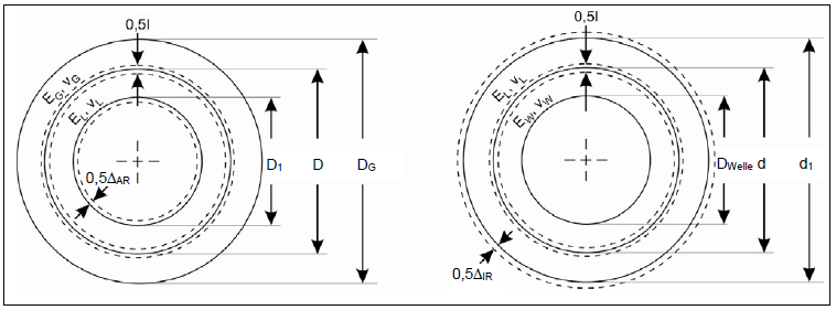
Narrowing of the outer ring raceway (left) and widening of the inner ring raceway (right)
The calculation is based on the theory of elastic rings. The reduction of the clearance is described in the following formulas:
where I is the corresponding effective interference, DWelle = inner diameter of the shaft, d = outer diameter of the shaft/inner diameter of the bearing, d1 = inner raceway diameter, D1 = outer raceway diameter, D = outer bearing diameter/bore diameter, DG = equivalent casing diameter. Furthermore EL, νL are the material parameters of the bearing (or bearing rings), EW, νW the material parameters of the shaft, and EG, νG the material parameters of the casing.
For many bearing types, it is not immediately clear which "raceway diameter" should be used. The detailed calculation uses the following convention: if the rolling element runs in a groove of the raceway, the "contact point" between the rolling element and raceway under the nominal contact angle is used. The same consideration is made with the midpoint of the roller for double-row tapered roller bearings. If the internal clearance of the bearing prior to installation is neglected, then:
For the detailed calculation according to FVA 364, the following simplified formulas are used to determine the raceway diameters:
Note: in most applications, the casing is not a hollow cylinder, but rather a more complex construction. Thorough consideration of such complex geometry requires extensive modeling and calculation details. The FVA-Workbench simplifies this by using the specified outer diameter of an equivalent hollow cylinder casing.
Simplified calculation according to FVA 364: With the "simplified calculation acc. to FVA 364" switch, the bearing rings are simplified as "stiff," and the determined interference (or loose fit) of the rings is directly considered as deformation of the raceways and calculated with the bearing clearance.
Temperature difference between the inner and outer ring
Temperature distribution in the bearing is uneven during operation. According to "Die Wälzlagerpraxis" ("Ball and Roller Bearings: Theory, Design, and Application") by Brändlein et. al., the temperature of the inner ring is 5-10 K higher than the outer ring (if the casing is air cooled, this difference increases to 15-20 K). This temperature difference causes the inner ring and the rolling elements to expand more than the outer ring, which leads to a reduction of the radial bearing clearance.
Considering a temperature difference between the inner and outer ring ΔTie, and assuming that the temperature of the rolling elements is in the middle, the radial bearing clearance is reduced by:
where ΔTie= temperature difference between the inner and outer ring, αbearing = 12e-6 mm/K coefficient of thermal expansion of the bearing, DW = diameter of the rolling element, d1 = inner raceway diameter.
When applying the detailed calculation according to FVA 364, the reduction in bearing clearance due to this temperature difference is approximated using the mean bearing diameter according to the SKF catalog:
Minimum/maximum operating clearance
Tolerance classes only specify an interval of permissible values. When specifying bearing tolerances, the corresponding combination of minimum and maximum dimensions can lead to large differences in the calculation of the operating clearance. For this reason, a mean, minimum, and maximum operating clearance are calculated. The user can choose which of these values is used for the subsequent stiffness and rating life calculations.
The minimum operating clearance is determined based on the minimum bearing clearance and the maximum interference in the bearing seats.
The mean operating clearance is determined based on the mean bearing clearance and the mean interference in the bearing seats.
The maximum operating clearance is determined based on the maximum bearing clearance and the maximum interference in the bearing seats.
In the detailed calculation, the mean interference is calculated as the most likely interference according to findings from FVA 736 I (rolling bearing tolerances). Due to manufacturing deviations, there is a high probability that the actual dimension is one third of the tolerance zone from the machining side.
In the calculation according to FVA 364, the mean interference is determined as the arithmetic mean between the minimum and maximum interferences.
Conversion of axial/radial clearance
The following section describes the formulas for converting radial to axial clearance, or vice-versa, depending on the type of rolling bearings.
Deep groove ball bearings: The following relationships can be derived from the figure below:
Conversion of radial to axial clearance:
Conversion of axial to radial clearance:
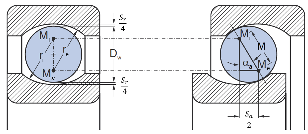
2-row angular-contact ball bearings/four-point ball bearings/self-aligning ball bearings/spherical roller bearings:
Consider a rolling element in three positions, with the outer ring fixed: The midpoint of the rolling element (or, for spherical roller bearings, the center of the of the outer radius of the roller) is labeled MWK; more precisely, MWK,α refers to a concentric position at which the rolling element is located exactly on the pitch circle, and the outer and inner rings are the same distance from the rolling element. Furthermore, MWK,r refers to the position at which the rolling element was moved in the radial direction until it made contact with the outer raceway, and MWK,a refers to the position at which the rolling element was moved in the axial direction until it made contact with the outer raceway. The distance between the center of the outer raceway groove Me and MWK,r, MWK,a is defined by re - 0.5 DW (or re - Rp for spherical roller bearings, where Rp is the outer radius of the spherical roller). Thus, for spherical roller bearings, the radius of the roller (0.5 DW) is replaced by the outer radius of the spherical roller (Rp).
Conversion of axial clearance to radial clearance:
Conversion of radial clearance to axial clearance:
2-row/paired tapered roller bearings:
Conversion of axial clearance to radial clearance:
Conversion of radial clearance to axial clearance:
Stiffness
The basic procedure for determining the bearing stiffness, or the bearing operating point, is as follows:
Setting up the mechanical model of the rolling bearing, taking the geometry and operating clearance into account, initial position = neutral position
Specification of the displacement and tilting of the inner ring relative to the outer ring
The axial and radial position (and also the tilting for roller bearings) under load is then determined for each rolling element, so that it is in force and moment equilibrium.
The outer reaction forces and moments of the bearing can be determined by summing the effective rolling element forces
If forces/moments are specified instead of displacement and tilting, the process described is applied multiple times in an iterative solution process until the reaction forces and moments correspond to the specifications.
Ball bearing stiffness
Calculation of the internal load distribution of radial and thrust ball bearings is based on ISO/TS 16281:2008 (or DIN 26281:2010) with extensions from FVA 364 and FVA 701. The following influences can be considered:
Specification of the relative displacements and tiltings of the inner ring relative to the outer ring (or, alternatively, specification of forces and moments with iterative solution of the associated displacements and tiltings)
Specification (or calculation) of the operating clearance
Consideration of the internal geometry of the bearing (curvature ratio, etc.)
Consideration of the centrifugal force of the rolling elements (optional)
Consideration of the ovalization of the outer/inner ring
Neutral position of the rolling elements: A right-handed Cartesian u,v,w-coordinate system is established, with its origin in the bearing center (half width, on the axis of rotation). Its axes are defined parallel to the shaft-coordinate system; in particular, the u-axis corresponds to the axis of rotation. The radial position of the rolling elements is determined by Dpw. The operating clearance sα is equally divided between the inner and outer raceways. Therefore:
For single-row bearings, the center of the rolling elements is on the radial plane through the bearing origin. The inner and outer rings (raceways) are positioned according to the axial force absorption of the bearing row, the contact angle, and the operating clearance. The sign (+/-) of the pressure angle is defined by the axial force absorption: α>0 = positive axial force absorption, α<0 = negative axial force absorption. Thus, for bearings in an X-arrangement, α1<0, α2>0; in an O-arrangement, on the other hand, α1>0, α2<0. The following applies for the centers of raceway groove radii:
Note: A special consideration applies for purely axial (thrust) bearings. The operating clearance specifies the mobility of the bearing rings from one limit position to the another. While the radial operating clearance is once again divided between an "upper" and "lower" rolling element, the axial operating clearance acts fully on all rolling elements. Therefore, 0.25 sα is generally used in the above formulas. For α=90°, this is replaced with 0.5s.
For double-row axial bearings, the centers of the rolling elements of the first row are shifted by -0.5 dR in the axial direction, and those of the second row are shifted by +0.5 dR. The values of ue and ui also change by -/+ 0.5 dR accordingly. If a bearing ring is ovalized, the center of the corresponding raceway curvature at the circumferential angle is also shifted by the corresponding amount in the radial direction. The operating clearance, etc. always assumes a circular bearing ring.
Note: Four-point bearings are modeled as 2-row angular contact ball bearings in an O-arrangement, in which each rolling element is "cloned." With sufficient axial load (Schaeffler: Fa≥1.20Fr , SKF: Fa≥1.27Fr), the rolling elements contact the inner and outer raceways at one point each. In this case, only one of the two rows is load bearing. Four-point contact leads to high friction and thus increased wear; therefore, this operating point should be avoided. The mechanical model in the FVA-Workbench does not ensure that that the rolling elements and their clones are in the same position during four-point contact. A corresponding warning is issued.
Hertzian contact: The Hertzian theory can be applied for calculation of the forces acting on the individual rolling elements. As long as the contact surfaces are small and the convergence of both rolling elements is relatively low for their size, the bearing rings and the balls near the point of contact can be represented as elliptical paraboloids. According to Hertz, the contact force Q over the elliptical contact surfaces with the semi-axes a and b determines the normal pressure distribution p(x,y) and the maximum deflection δ
where Q is the contact force, E the modulus of elasticity, ν Poisson's ratio, Σρ the total curvature of both bodies, κ the ratio of the two half-axes of the Hertzian contact ellipse, and K(κ) and E(κ)the complete elliptical integral of the first and second kind.
Force equilibrium on the rolling element: Consideration of the radial, outward-acting centrifugal force Qc results in different working pressure angles between the rolling element and the inner (αi) or outer (\(αe) raceways. The following equilibrium of force applies for the rolling bearing forces on the inner and outer raceways Qi, Qe (see FVA 701 III final report):
The centrifugal force of a ball is calculated as:
Note: Frictional effects between the rolling element and raceway along with gyroscopic effects play a minor role and are neglected, as in FVA 701 III.
Resulting bearing forces: Fu, Fv, Fw are the sum force components from the shaft acting on the inner ring. The following applies (pay particular attention to the sign convention for αi and αe):
Resulting tilting moment: Contact forces acting between the inner ring of the bearing and the rolling elements cause tilting moments about the bearing center if the line of action of the force does not go through the center of the bearing. To determine the resulting tilting moment from the inner or outer ring contact, the respective contact force can be shifted along the line of action to the center of the rolling element.
Let PWK be the current position of the center of the bearing and rP the distance between the centers of the bearing and rolling element. Define the coordinate system u, r, s; where u corresponds to the u-axis of the bearing, r is the radial vector associated with the position angle of the rolling element φ, and s is the cross product of the two. Let ψWK be the position angle of PWK about s from the r-axis. Then, the force QWK,i which acts from the inner raceway onto the rolling element causes the moment MψWK about the s-axis:
where the effective share of the tangential force is determined by
Finally, the formulas for the resulting tilting moment in the bearing are as follows:
Note: In DIN 26281 and some other publications, various simplifications are made in the calculation of the tilting moment. Most use the following formula:
Thus, the pitch circle radius is used as the lever arm, independent of the exact point of contact and the position of the rolling element under load. The tangential force which causes the moment is also usually not equal to the axial force.
Roller bearing stiffness
Calculation of the internal load distribution of radial and axial roller bearings is based on ISO/TS 16281:2008 (or DIN 26281:2010) with enhancements from FVA 364 and FVA 701. The following influences can be considered:
Specification of tilting and displacements of the inner ring relative to the outer ring (or, specification of forces and moments with iterative solution of the associated tilting and displacements)
Specification (or calculation) of the operating clearance
Consideration of the bearing inner geometry (profiling, etc.)
Consideration of the centrifugal force of the rolling elements (optional)
Consideration of ovalization of the outer/inner ring
Neutral position of the rolling elements: The geometric center M of the rolling element is the starting point for all calculations. Its radial position is determined by the pitch circle diameter Dpw, the axial position corresponds to the axial position of the bearing row (0 for single-row bearings, 0.5 dR for double-row bearings). At M, the rolling element has the diameter DW (measured perpendicular to the roller axis). Let αn be the nominal contact angle = contact angle at the outer ring contact, and ε the semicone angle of the roller (ε=0 if there are no tapered roller bearings). The value for the contact angle at the inner ring contact is αn-2ε, and the longitudinal axis of the roller is tilted by the angle αn-ε. The center of the running surfaces on the inner and outer rings are designated Pi and Pe respectively. The corresponding diameters (taking the operating clearance into consideration) can be calculated as:
Similarly, the axial position of Pi and Pe can be determined by offsetting M by the term sin(|αn|-ε)( 0.5DW + 0.25 sα). The equivalent cylindrical diameter of the roller to be used for calculation of the contact is calculated as cos(ε)DW.
Disc model: In general, the Hertzian and Palmer's equations cannot be directly applied for roller bearings. The Hertzian equations only apply for contact between cylinders of an infinite length. Palmgren's equation considers the finite dimensions of the rolling elements, but only applies for a centric load on the roller:
where δ represents the total deflection of the roller and Q the resulting contact force (for example, compare ISO/TS 16281:2008 or AB FVA 364 II Section 2.9.2). The disc model according to ISO/TS 16281 is typically used in order to be able to consider effects such as tilting of the roller, profiling, rib contact, centrifugal force, etc. For calculation of the deflection, the roller is divided into ns equal slices; according to ISO/TS 16281, the minimum number of slices should be at least ns = 30. The corresponding line load for the operating conditions of the bearing are determined for every disc contact. This is done using the disc deformations and Palmer's equation for the discs. The disc method assumes a two-dimensional stress state for the individual discs to calculate the line loads. This ignores the cross-influences, and thus the shear stresses between the discs. Therefore, in the disc method the individual discs are pushed together independent of the deflection of the neighboring discs.
The deformation-force relationships from R. Teutsch and B. Sauer “An alternative slicing technique to consider pressure concentrations in non-Hertzian contacts", J. Tribol 126(3), 436-442 (2004), can be used as an alternative to the feather model according to ISO/TS 16281 (Palmgren). These are based on a regression model which uses an explicit formula to approximate the implicit deformation-force relationship for line contact established by Dinnik. In contrast to Palmgren, this formula explicitly considers the material characteristics, rolling element diameter and pitch circle diameter, and the thickness of the outer ring and the housing ring.
Force and moment equilibrium on the rolling element: The following influencing factors on the force equilibrium of a rolling element must potentially be taken into account in order to be able to consider all use cases:
Load distribution of the inner ring contact (taking the profiling into consideration)
Load distribution of the outer ring contact (taking the profiling into consideration)
Tapered rolling elements, if applicable (i.e., non-parallel application of force for the inner and outer rings)
Rib contact, if applicable (cylindrical and tapered roller bearings)
Centrifugal force, if applicable
The following applies to tapered roller bearings in axial and radial force equilibrium:
where Qc represents the centrifugal force of the roller and QB,i/e the on-board force on the inner/outer ring. The general moment equilibrium is determined as:
where the prefixes (+/-) of the excentricity are determined such that e>0 at the exact point where the force causes a positive (rightward-turning) moment.
Resulting bearing forces and tilting moments: The forces and tilting moments resulting from the loading of the individual rolling elements are determined similar to the process described for ball bearings.
Rating life
Bearing rating life is defined as the number of rotations of a bearing ring or plate relative to the other bearing rings or discs before the first sign of material fatigue becomes visible on one of the two rings or discs or a rolling element. The bearing rating life is typically determined according to ISO 281:2007, possibly supplemented by the reference rating life according to ISO/TS 16281:2008 as well as the respective catalog methods of the bearing manufacturers.
The fundamental work for determining the bearing load ratings and the typical methods for determining the bearing rating life dates back to Lundberg and Palmgren. The method is empirical and is based on the observed relationship between the survival probability and the load, number of rotations, volume, and the depth at which the maximum orthogonal shear stress occurs.
According to Lundberg/ Palmgren, the following relationship applies for the basic rating life:
where the dynamic load rating C corresponds to a bearing load which is invariable in magnitude and direction, at which a rolling bearing can withstand one million rotations with a survival probability of 90 %. Thus, C represents the component strength, which depends on the bearing type and size, as well as the operating conditions under which it was determined. The equivalent dynamic load P is a load which is invariable in magnitude and direction, under whose influence a rolling element achieves the same rating life as under the actual load conditions. The bearing rating life exponent p is p=3 for point contact and p=4 for pure line contact. As either point or line contact can occur in the inner and outer rings, depending on the operating point, a value of p = 10/3 is considered as appropriate for roller bearings.
As can be directly observed, this approach cannot be used to represent fatigue strength. This is due to the fact that fatigue strength could not be achieved experimentally with the typical materials and manufacturing methods at the time the rating life theory was developed (ca. 1940 - 1950). Proof of the fatigue strength, which is also present in rolling bearings, was published by FAG/Lorösch in 1981.
Different survival probabilities, lubricant conditions and contamination, and fatigue limit loads of the raceway material can be considered in the modified rating life calculation. ISO 281:2007 establishes a rating life coefficient a1 for reliability and rating life coefficient aISO for the system analysis.
ISO 281
The International Organization for Standardization (ISO) is the international association of standards bodies (e.g. DIN, ANSI, …). 164 countries are currently represented in the ISO (121 full members, 39 corresponding members, and 4 observers). For more information, see refer to the ISO website at www.iso.org.
There are 249 different Technical Committees (TC). TC 4 is responsible for rolling bearings, and rolling bearing rating life is discussed in Sub Committee (SC) 8. ISO 281 is developed in ISO/TC 4/SC 8. whose secretariat is administered by the German Institute for Standardization (www.din.de). The responsible German body is working committee NA 118-01-08 AA, "load ratings and rating life" in the Rolling and Plain Bearings Standards Committee (Normenausschuss Wälz- und Gleitlager, NAWGL).
Generally speaking, the application of standards is voluntary; standards are non-binding. Standards become legally binding when laws or legal regulations, such as EU directives, refer to them. Contractual partners may also specify the application of standards in their agreements.
The current version of ISO 281 is from 2007, and replaces the withdrawn standards ISO 281:1990 , ISO 281:1990/AMD 1:2000 , ISO 281:1990/AMD 2:2000, and ISO/TS 16799:1999. The current German version is DIN ISO 281:2010-10, and replaces the withdrawn standards DIN ISO 281:1993-01, DIN ISO 281:2009-01, DIN ISO 281/A1:2001-09, and DIN ISO 281/A2:2001-09.
Scope: "This International Standard specifies methods of calculating the basic dynamic load rating of rolling bearings within the size ranges shown in the relevant ISO publications, manufactured from contemporary, commonly used, high quality hardened bearing steel, in accordance with good manufacturing practice and basically of conventional design as regards the shape of rolling contact surfaces.
This document also specifies methods of calculating the basic rating life, which is the life associated with 90 % reliability, with commonly used high quality material, good manufacturing quality and with conventional operating conditions. In addition, it specifies methods of calculating the modified rating life, in which various reliabilities, lubrication condition, contaminated lubricant and fatigue load of the bearing are taken into account.
This International Standard does not cover the influence of wear, corrosion and electrical erosion on bearing life. This document is not applicable to designs where the rolling elements operate directly on the shaft or housing surface, unless that surface is equivalent in all respects to the bearing ring (or washer) raceway it replaces. Double-row radial bearings and double-direction thrust bearings are, when referred to in this document, presumed to be symmetrical." [DIN ISO 281:2010 Section 1]
Calculation scope: The central calculation variables for ISO 281 are:
Nominal rating life L10: The calculated rating life achievable with 90 % reliability, with commonly used high quality material, good manufacturing quality and with conventional operating conditions
Modified rating life Lnm: The calculated rating life for 90% or better reliability, modified for the fatigue limit load of the bearing, and/or special bearing characteristics, and/or lubrication contamination, and/or other atypical operating conditions.
To determine the nominal rating life L10, the dynamic load rating of the bearing is compared with the equivalent dynamic load. The number and diameter of the rolling elements as well as the effective roller length for roller bearings have a significant influence on the determination of the dynamic load ratings according to ISO 281. The load ratings provided by the bearing manufacturers are used for the ISO 281 calculation in the FVA-Workbench. The equivalent dynamic load as a function of the radial and axial bearing forces is determined by:
where the load factors X and Y are automatically determined in the FVA-Workbench according to ISO 281 specifications.
The modified rating life considers the rating life coefficient a1 for the reliability as well as the rating life coefficient aISO for the system analysis:
The rating life coefficient a1 can be influenced by the choice of reliability to be considered. The rating life coefficient aISO is determined as a function of the fatigue limit load Cu, the contamination (contamination coefficient eC), the lubrication conditions (viscosity ratio κ), and the bearing load P.
Limitation: The influence of the bearing clearance, tilting under general operating conditions, etc. are only considered in ISO 281 by their influence on the effective bearing forces. More precise consideration of the bearing rating life, taking the internal load distribution of the rolling bearing into account, is provided by ISO/TS 16281 (DIN 26281).
Geometry dependence for ball bearings: Even with a specified fixed bearing load (forces), the rating life according to ISO 281 can change due to changes to the internal geometry. This is due to the geometry-dependent load factors in ISO 281(Table 3). Therefore, the equivalent dynamic load P and thus the rating life coefficient aISO are geometry-dependent.
DIN 26281 (ISO/TS 16281)
The current version of ISO/TS 16281 was published in 2008; a corresponding corrigendum was issued in 2009. ISO/TS stands for "Technical Specification." These may be issued when the "subject matter concerned is still under development or when, for other reasons, there is the possibility of a subsequent but not imminent agreement on the publication of an international standard." DIN 26281:2010 is the German-language version of ISO/TS 16281 and replaces DIN ISO 281 Supplement 4 from 2003.
Scope: "This standard contains recommendations for the calculation of the modified reference rating life taking into consideration lubrication, contamination and fatigue load limit of the bearing material, as well as tilting or misalignment, operating clearance of the bearing and internal load distribution on rolling elements. The calculation method provided in this standard covers influencing parameters additional to those described in ISO 281.
The directions and limitations given in ISO 281 apply to this standard. The fatigue life of the bearings is calculated. Other mechanisms of failure, like wear or microspalling (gray staining), are not taken into account in this standard.
This standard applies to tilted single-row radial ball bearings, subjected to radial and axial load and with radial clearance and tilt taken into account. It also applies to tilted single-row roller bearings, subjected to pure radial load and with radial clearance, edge stress and tilt taken into account. References to methods for the analysis of the internal load distribution under general load are given.
The analysis of internal load distribution and modified reference rating life for multi-row bearings or bearings of a more complex geometry can be derived from the equations given in this standard. For these bearings, the load distribution for each individual row has to be considered." [DIN 26281:2010]
Implementation in the FVA-Workbench: The necessary extension of the calculation methods in DIN 26281 to general operating conditions and more complex bearing geometries is based on the FVA Research Projects 364 and 701. For example, this includes the extension of the method to double-row bearings or the exact determination of the dynamic load rating of a washer for spherical and tapered roller bearings. The calculation methods for determining the internal load distribution in the bearing also significantly extend the scope of DIN 26281, for example by taking centrifugal force into account. Details on determining the internal load distribution are documented in the stiffness section.
Calculation of the rating life according to DIN 26281 is only possible if the internal bearing geometry is known (user specification, XML bearings, or bearings from the FVA Bearing Catalog).
Calculation scope: In addition to the detailed definition of the internal load distribution (and thus the bearing operating points/the resulting bearing forces and moments), the central result variables in DIN 26281 are the:
Nominal reference rating life L10r: The calculated rating life achievable with 90 % reliability, with commonly used high quality material, good manufacturing quality and with conventional operating conditions (corresponds to L10 in ISO 281 but with a higher quality method)
Modified reference rating life Lnmr: The calculated rating life for 90% or better reliability, modified for the fatigue limit load of the bearing, and/or special bearing characteristics, and/or lubrication contamination, and/or other atypical operating conditions (corresponds to Lnm in ISO 281 but with a higher quality method)
The most signification difference to the calculation according to ISO 281 is that the load and load capacity of the individual rolling element contacts are used to determine the rating life. For ball bearings, the dynamic load rating of the individual contact for the inner and outer ring is also determined from the load rating of the bearing and the geometric parameters. In contrast, the dynamic equivalent loads of the inner and outer ring contact are determined from the effective rolling element forces. For rolling bearings, the dynamic load rating of a roller washer on the inner and outer ring is determined based on the load rating of the bearing and the geometric parameters. This is then compared to the dynamic equivalent load rating of a washer on the inner and outer ring. The dynamic equivalent reference load of the bearing is then obtained from the load rating of the bearing and the calculated nominal reference rating life. The rating life coefficient a1 for the reliability and rating life coefficient aISO are also used to determine the modified reference rating life. These are determined according to the specifications in ISO 281, but the dynamic equivalent reference load (ball bearings) or the dynamic equivalent load of the bearing washer (roller bearings) are taken into account for determining aISO.
Determination of the load distribution and pressure of roller bearings: As described in the roller bearing stiffness section above, the disc method ignores cross influences between the discs, and the deflection of one disc has no influence on the neighboring discs. Therefore, this method cannot be used to determine any edge pressures that may occur (due to insufficient profiling/excessive tilting), in particular.
DIN 26281offers a simple approximation to correct the load distribution determined using the disc method to consider the effect of the influence of shear stress and any resulting edge stresses using the empirical load increase function according to equation (60) of DIN 26281 (2010). This can only be used for the approximate profile according to DIN 26281, and only under moderate load conditions and with tilting of the bearing of less than 4 angular minutes. A higher-quality calculation is recommended for general calculations.
Alternatively, a calculation method can be used that considers the influence of the shear stress on the discs. This can be used to calculate the edge effects for any roller profile and consider them in the rating life calculation, thus considering the load of a disc on the deformation of the neighboring discs. The current bearing calculation in the FVA-Workbench uses the influence coefficient matrix from R. Teutsch and B. Sauer, “An alternative slicing technique to consider pressure concentrations in non-Hertzian contacts", J. Tribol 126(3), 436-442 (2004). The FVA 364 bearing calculation uses the method according to the H. Reusner dissertation, "Druckflächenbelastung und Oberflächenverschiebung im Wälzkontakt von Rotationskörpern" ("Contact Area Loading and Surface Displacement in Rolling Contact of Rotating Bodies"), Karlsruhe University, 1977
Power loss
SKF calculation service
The SKF calculation service is a free service from SKF which makes it possible to perform calculations with the actual geometries of SKF bearings (number of rolling elements, curvature ratio (osculation)/roller profiles, etc.). As a result of the calculation, the bearing operating point and various bearing rating lives are available.

SKF Calculation Service in the FVA-Workbench
Note
When using the SKF calculation service, the FVA-Workbench internal bearing calculation modules are not used for this bearing.
Requirements:
A "My SKF" user account is required to use the SKF calculation service. Click here to register. SKF's privacy policy and terms and conditions apply.
The 'My SKF' account information must be entered in the FVA-Workbench settings.
An Internet connection is required to contact the SKF server.
Process for system calculations:
Activation: Activate the "Use SKF calculation service for SKF bearings" switch under the Control Parameters tab for the Gear Unit.
Input: Select the bearing from the SKF catalog, define the operating clearance and any relevant lifetime parameters (survival probability, lubrication conditions, etc.).
Calculation of the operating point: The operating point (bearing reaction forces and tilting moments as well as the Jacobian matrix) is determined for each SKF bearing in the system iteration based on the displacement and tilting of the inner ring relative to the outer ring. The input data is automatically sent to the SKF calculation service server, which calculates the bearing operating point and returns the results to the FVA-Workbench. The following influencing factors are taken into consideration in the calculation:
The actual bearing inner geometry (number and diameter of the rolling elements, etc.)
The actual curvature ratio/osculation (ball bearings) or roller profile (roller bearings)
User-defined operating clearance. For cylindrical roller bearings, the axial clearance according to the tolerance specifications in the SKF catalog is also considered.
Centrifugal forces of the rolling elements
Calculation of the bearing rating life: If calculation of the bearing rating life is activated in the system calculation, the nominal and extended lifetime according to ISO/TS 16281 are determined for each bearing by the SKF calculation service following the system calculation.
nominal and modified rating life according to ISO/TS 16281
nominal and modified rating life according to SKF (available from FVA-Workbench 9.0)
Friction and power loss calculation (available from FVA-Workbench 9.0)
Rollover frequencies (available from FVA-Workbench 9.0)
Static safety (available from FVA-Workbench 9.0)
Adjusted reference speed (available from FVA-Workbench 9.0)
Minimum load calculation (available from FVA-Workbench 9.0)
Grease life and relubrication intervall (available from FVA-Workbench 9.0)
Results: Bearing reaction forces and tilting moments, Jacobian matrix. The bearing rating life, etc. calculated by the SKF calculation service can be found in separate attributes. Some of them are listed in the system calculation report, a more detailed overview is available in the report template SKF Calculation Service.
Process for single component calculations: Select the "SKF calculation service" objective for an individual bearing. In addition to the information required for the system calculation above, the operating point must also be specified. The input data is automatically sent to the SKF calculation service server. The following options are available:
Specification of relative displacements and tilting from inner to outer ring: The bearing reaction forces and tilting moments, the Jacobian matrix and all the results listed above under "Calculation of bearing service life" are available as results.
Specification of bearing forces: The exact operating point is not determined, all "catalog calculations" (service life according to SKF, power loss calculation, ...) are carried out.
Limitations:
The SKF calculation service is not available for the following bearings, among others:
Bearings from other manufacturers
SKF super-precision bearings
SKF bearings for extreme temperatures
When the SKF bearing service is used, the FVA-Workbench's internal bearing calculation model is not used for this bearing. This means in particular that the results for the (estimated) internal geometry of the bearing are not available.
Sources
Standards
ISO 281:2007 Rolling bearings — Dynamic load ratings and rating life
DIN ISO 281 Rolling bearings — Dynamic load ratings and rating life
DIN ISO 76:2019 Rolling Bearings - Static Load Ratings (ISO 76:2006 + Amd.1:2017)
ISO/TS 16281:2008 Rolling bearings — Methods for calculating the modified reference rating life for universally loaded bearings
ISO/TS 16281:2008/COR 1:2009 Rolling bearings — Methods for calculating the modified reference rating life for universally loaded bearings — Technical Corrigendum 1
DIN ISO 26281:2010 Rolling bearings - Methods for calculating the modified reference rating life for universally loaded bearings (ISO/TS 16281:2008 + Cor. 1:2009)
ISO 286-2:2010 Geometrical product specifications (GPS) — ISO code system for tolerances on linear sizes — Part 2: Tables of standard tolerance classes and limit deviations for holes and shafts
ISO 492:2002 Rolling bearings — Radial bearings — Tolerances
DIN 620-4:2004 Rolling bearings - Rolling bearing tolerances - Part 4: Radial internal clearance
DIN 628-3:2008 Rolling bearings - Angular contact radial ball bearings - Part 3: Double row
DIN 628-4:2008 Rolling bearings - Angular contact radial ball bearings - Part 4: Single row, double-direction - not self-locking, with double-split inner ring (Four-point contact bearing)
Research content
Aschenbrenner, A.; Dahiwal, R.; Kiekbusch, T.; Tremmel, S., Sauer, B., Wartzack, S.: FVA-Nr. 736 I - Heft 1255 - Wälzlagertoleranzen. Grundlagen zur Überarbeitung des Wälzlagertoleranzschemas, Abschlussbericht, Forschungsvereinigung Antriebstechnik e.V., Frankfurt am Main (2017).
Breuer, M.; Paland, E.-G.: FVA-Nr. 184 I - Heft 375 - Lagersteifigkeit - Programm zur Berechnung der (Wälz-)Lagersteifigkeit, Programmdokumentation, Forschungsvereinigung Antriebstechnik e.V., Frankfurt am Main (1993).
Harris, T. A.; Kotzalas, M. N. - Advanced concepts of bearing technology. CRC Press, Boca Raton, Fla., 5. ed. (2007).
Hertter, T.; Oster, P.; Höhn, B.-R.: FVA-Nr. 364 I - Heft 674 - Lebensdauer-Industriegetriebe-Wälzlager - EDV-Unterprogramm zur Berechnung der Steifigkeit und der Lebensdauer von Wälzlagern, Abschlussbericht, Forschungsvereinigung Antriebstechnik e.V., Frankfurt am Main (2002).
Jurkschat, T.; Otto, M.; Stahl, K.: FVA-Nr. 364 IV - Heft 1145 - Lebensdauer-Industriegetriebe-Wälzlager IV (Erweiterung Lager 2) - Erweiterung von LAGER2 zur Dimensionierung von Wälz-lagern in Industriegetrieben: Verlustleistung und Betriebstemperatur, Abschlussbericht, Forschungsvereinigung Antriebstechnik e.V., Frankfurt am Main (2015).
Jurkshat, T.; Wang, D.; Otto, M.; Poll, G.; Stahl, K.: FVA-Nr. 701 I - Heft 1157 - Low Friction, Lager 2 (Wälzlager Reibungsberechnung). Erweiterung der Berechnung der Wälzlagerreibung in FVA-Software, Abschlussbericht, Forschungsvereinigung Antriebstechnik e.V., Frankfurt am Main (2015).
Kehl, J.H.; Zander, M.; Bötcher, R.; Otto, M.; Poll, G.; Stahl, K.: FVA-Nr. 701 III - Heft 1404 - Erweiterung LAGER2. Erweiterung der Wälzlagerberechnung in FVA-Software, Abschlussbericht, Forschungsvereinigung Antriebstechnik e.V., Frankfurt am Main (2020).
Leonhardt, C.; Otto, M.; Stahl, K.: FVA-Nr. 364 V - Heft 1185 - Lebensdauer-Industriegetriebe-Wälzlager - Erweiterung von LAGER2 zur Dimensionierung von Wälzlagern in Industriegetrieben: Mechanische Kontaktgrößen und Tragfähigkeitskennwerte, Abschlussbericht, Forschungsvereinigung Antriebstechnik e.V., Frankfurt am Main (2016).
Lundberg, G. - Elastische Berührung zweier Halbräume. Forschung auf dem Gebiete des Ingenieurwesens 10. Heft: 5, S. 201–211 (1939).
Palmgren, A. - Neue Untersuchungen über Energieverluste in Wälzlagern. VDI-Berichte. Heft: Band 20, S. 117–121 (1957).
Palmgren, A., Grundlagen der Wälzlagertechnik. 3. Auflage, Francksche Verlagsbuchhandlung, Stuttgart, 1964
Reusner, H. - Druckflächenbelastung und Oberflächenverschiebung im Wälzkontakt von Rotationskörpern, Dissertation, Technische Hochschule Karlsruhe (1977).
Schleich, T.; Otto, M.; Stahl, K.: FVA-Nr. 364 III - Heft 971 - Lebensdauer-Industriegetriebe-Wälzlager III - Erweiterung der FVA Programme RIKOR und LAGER2 zur Bestimmung der Lebensdauer von Wälzlagern in Industriegetrieben, Abschlussbericht, Forschungsvereinigung Antriebstechnik e.V., Frankfurt am Main (2011).
Teutsch, R.; Sauer, B.: An alternative slicing technique to consider pressure concentrations in non-Hertzian contacts, J. Tribol 126(3), 436-442 (2004).
Weitl, R. M.; Oster, P.; Otto, M.; Höhn, B.-R.: FVA-Nr. 364 II - Heft 848 - Lebensdauer-Industrie-getriebe-Wälzlager II - Erweiterung des EDV-Unterprogramms LAGER2 zur Berechnung der Steifigkeit und der Lebensdauer von Wälzlagern, Abschlussbericht, Forschungsvereinigung Antriebstechnik e.V., Frankfurt am Main (2008).