FEM Wheel Bodies
This tutorial will demonstrate the process for importing, positioning, and meshing CAD wheel bodies in the FVA-Workbench.
The following files are required to follow along with this tutorial in the FVA-Workbench:
Load the gearbox model and import the CAD wheel body
Load the gearbox model cad_wheelbody.wbpz:
Project -> Open
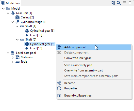
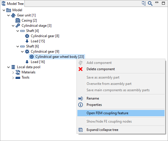
Right-click on Cylindrical gear [9] in the Model Tree and add a new wheel body component.
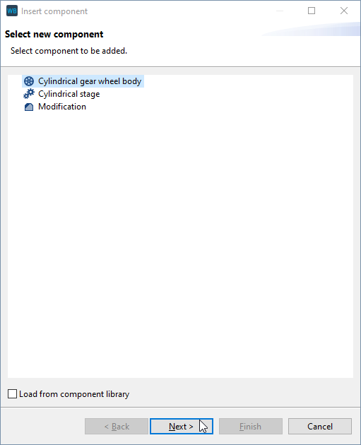
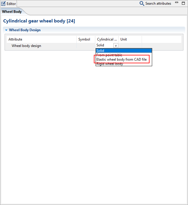
Right-click on the new wheel body component and choose "Open FEM coupling feature." Select "Elastic wheel body from CAD file" in the drop down menu under wheel body design.
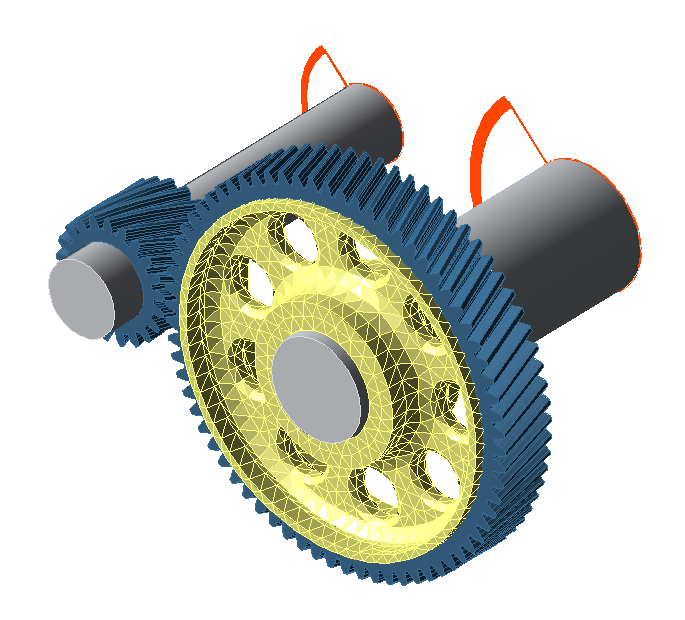
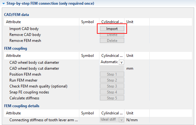
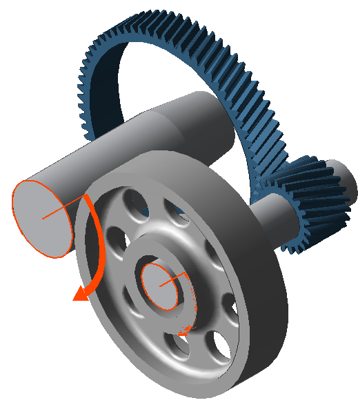
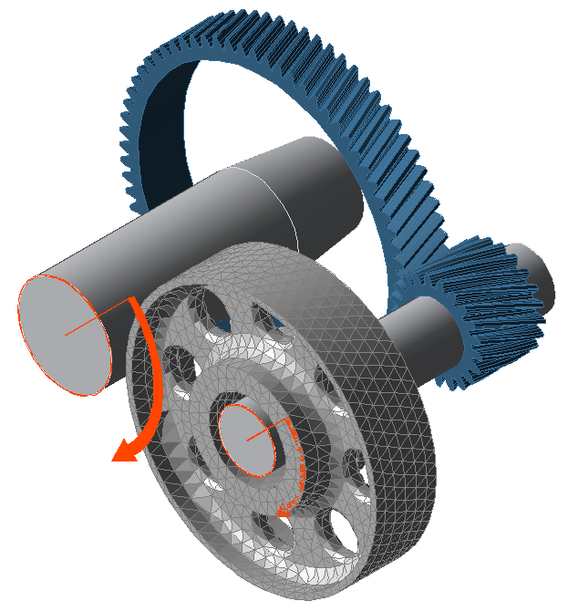
Click "Import" under "CAD/FEM data." Select the cad_wheelbody.stp file. Confirm mm as the unit for the model. The wheel body is initially placed in space independent of the gear model.
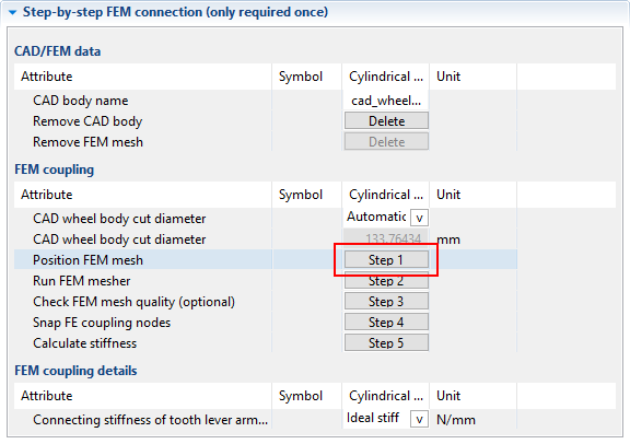
Position the wheel body
Click "Position FEM mesh"
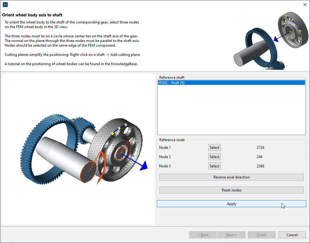
Determine the center axis
Select three nodes that form a circle whose center lies on the shaft axis of the gear. It is recommended to select three nodes along the edge of the CAD model. To do so, click "select" and then click on a mesh node. When all 3 nodes are selected, click "Apply" and then "Next."
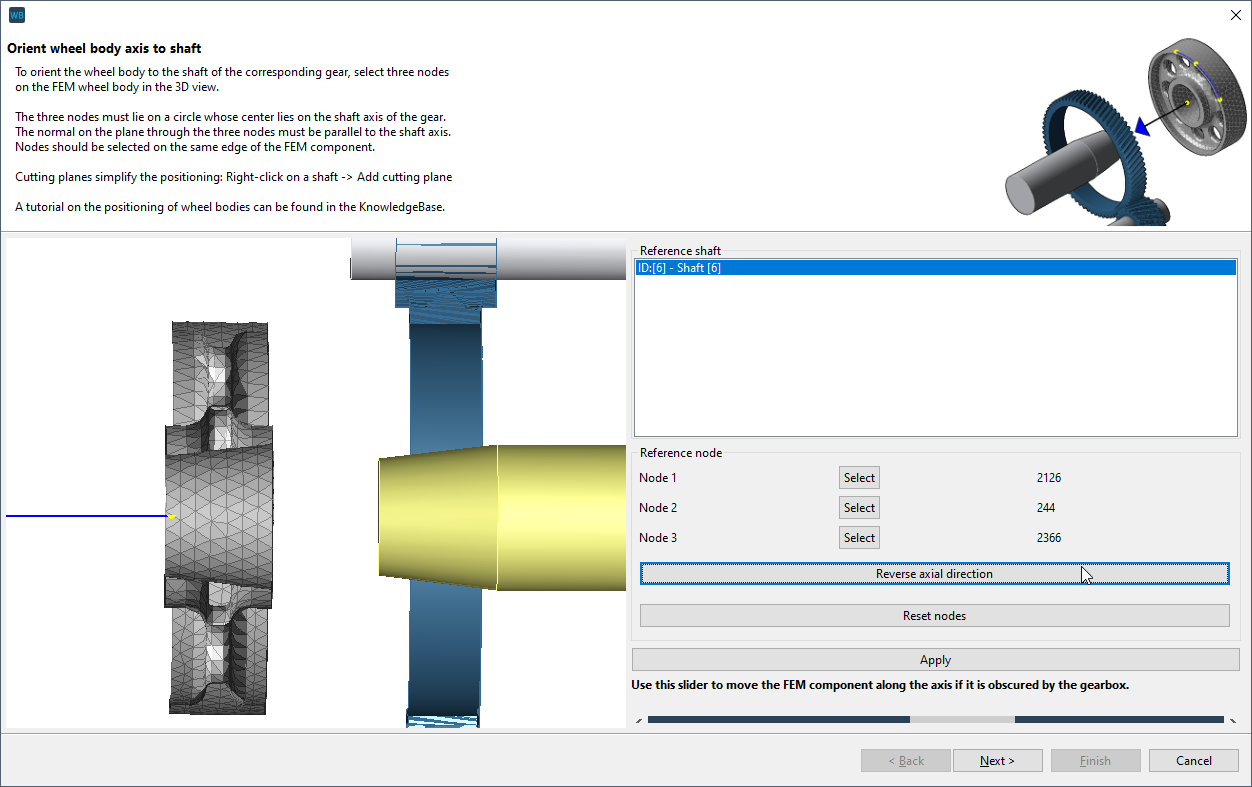
Notice
This model contains a tapered interference fit on the hub side. If the orientation is incorrect, click "reverse axial direction."
Axial positioning
For the axial positioning, select a node that is located on the left or right edge of the gear.
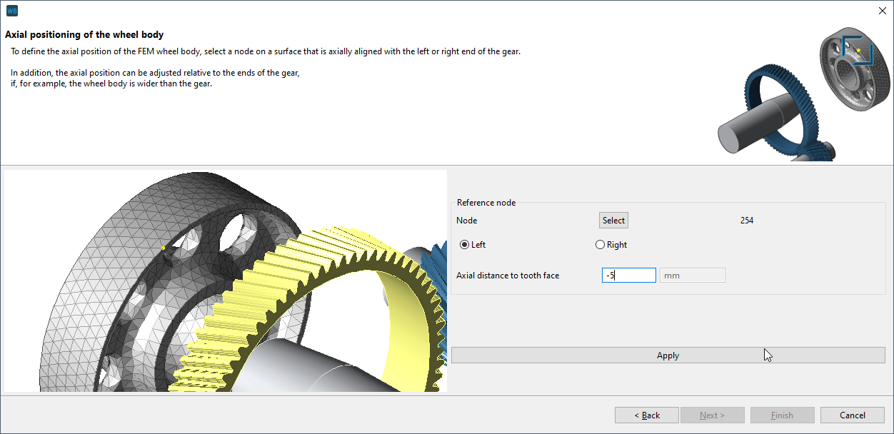
To position the wheel body axially centered on the gear, select a boundary node to be placed under the gear (see image) and enter -5 mm as the distance to the gear face. The prefix (-5 or +5mm) may vary, depending on where the node is selected.
Rotational position of the wheel body
One, two, or three reference nodes can be selected to define the rotational position of the wheel body relative to a tooth gap. In this case, one of the bores in the wheel body should be used as a reference. Select three nodes that form a circle whose center corresponds to the center of one of the bores. Click "Apply" and then "Finish."
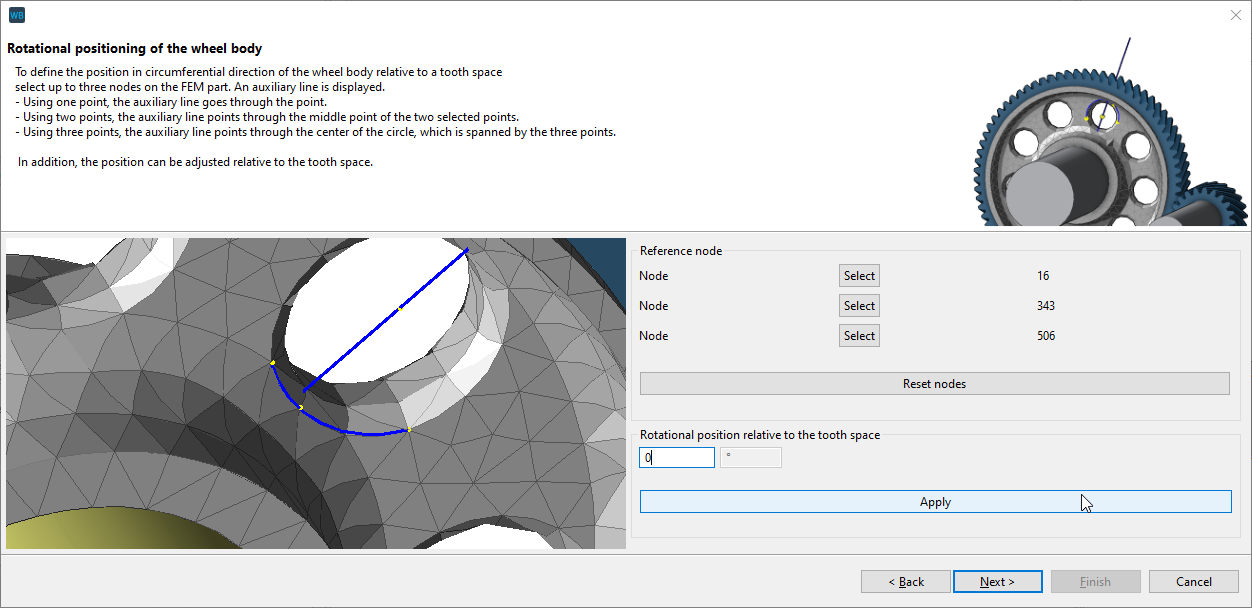
The position of the wheel body can be precisely specified using the "rotational position relative to the tooth space" input field. The flag shown serves as a guide.
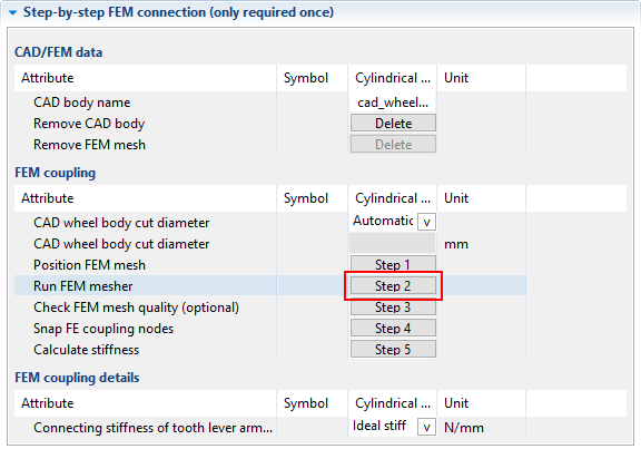
Meshing the wheel body
Click "Run FEM mesher."
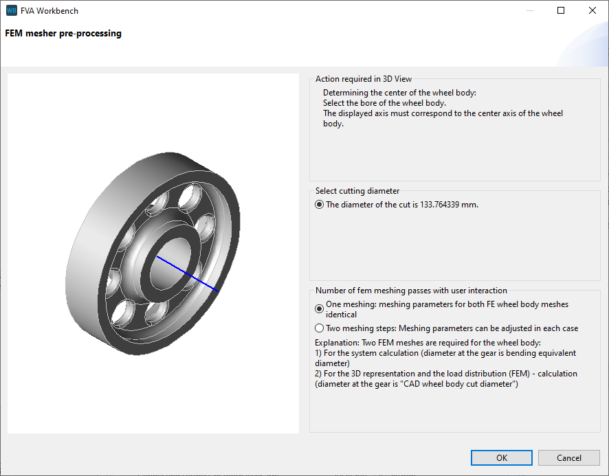
Define the center axis
Click on the bore to determine the center axis. The axis shown must be located exactly in the center of the wheel body.
Meshing
The default meshing parameters can be used. Click "preview surface mesh" to see a preview of the FE mesh. For more information, see Meshing the wheel body.
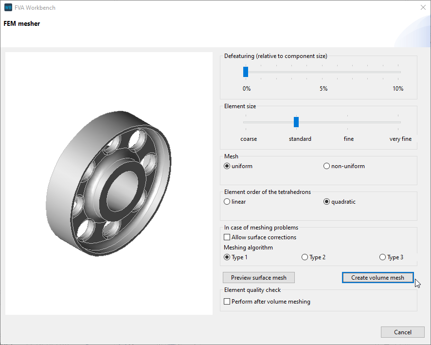
If the surface mesh meets your requirements, click "create volume mesh" to complete the meshing process.
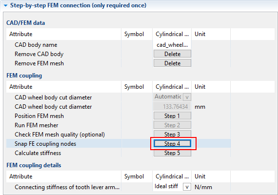
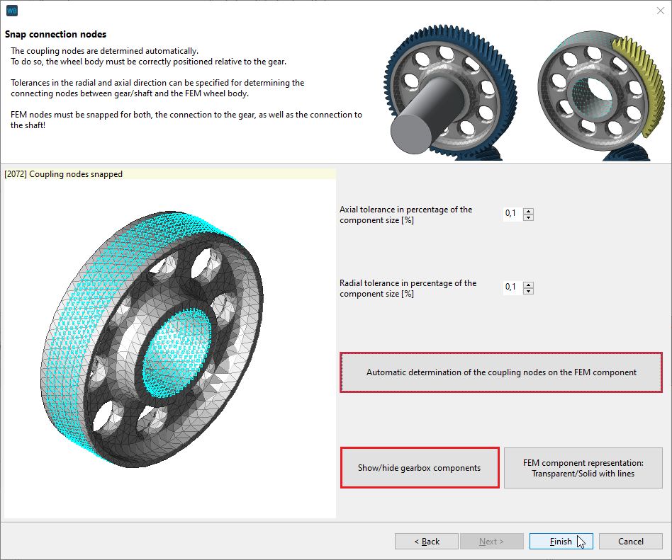
Click "Snap coupling nodes"
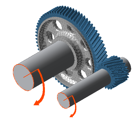
The coupling nodes between the gear and the wheel body are automatically determined. You can visually check whether the snapped nodes meet your expectations. Use the "hide gear" feature to get a better view of the coupling nodes under the gear.
If the position of the snapped coupling nodes does not meet expectations, adjust the position of the wheel body (or the geometry).
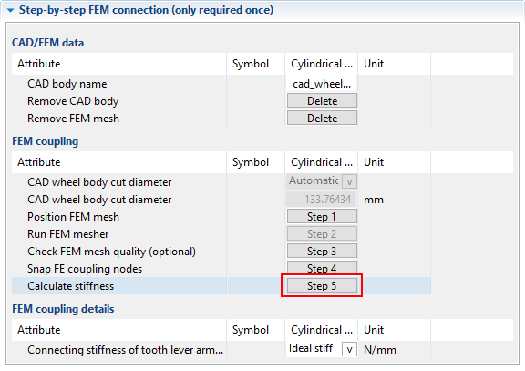
Run the calculation
Click "Calculate stiffness" to execute the calculation.