FVA-Workbench 8.1.0
Features
The new Variation of cylindrical gear stage geometry module can quickly and clearly optimize the geometry of existing cylindrical gear stages with regard to their load capacity, efficiency, and weight.
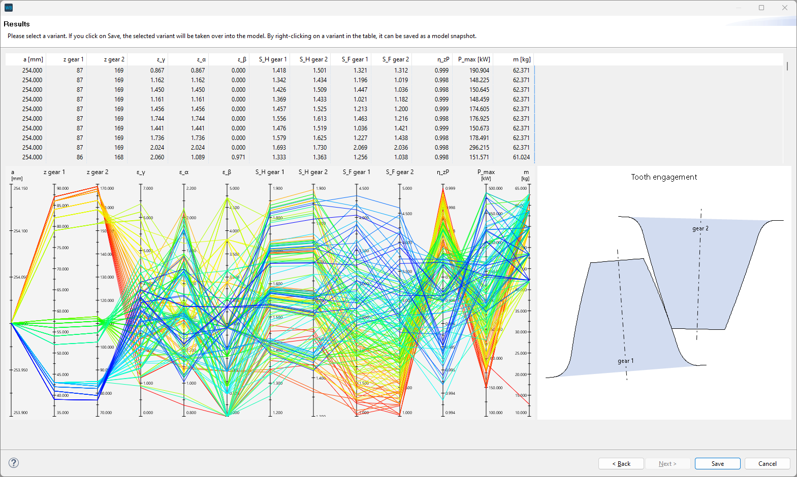
Visualization of the parameters for all calculated variants as a table and parallel coordinate diagram
A cylindrical gear stage must be selected in the Model Tree to start the variation. The parameters to be varied are defined in the first step. The start and end values as well as the step size can be specified for each parameter. Variations can be filtered and the parameters to be displayed in the evaluation can be selected in the second step. The final step is the evaluation, in which all variants are visualized in tabular form and as a parallel coordinate diagram. This can be used to reach conclusions about how the individual parameters influence each other.
After the variation is completed, each variant can be saved as a model snapshot and used for further calculations and comparisons.

Variation of cylindrical gear stages in the FVA-Workbench
This module can approximate the operating behavior of journal bearings based on predefined dimensionless tables to achieve a good compromise between accuracy and calculation time. These bearing tables are significantly better at representing the system behavior compared to a stiff calculation of the bearings with subsequent detailed simulation. The bearing loads and load distribution can also be determined more accurately in some cases, and the bearing losses can be considered in the overall system.
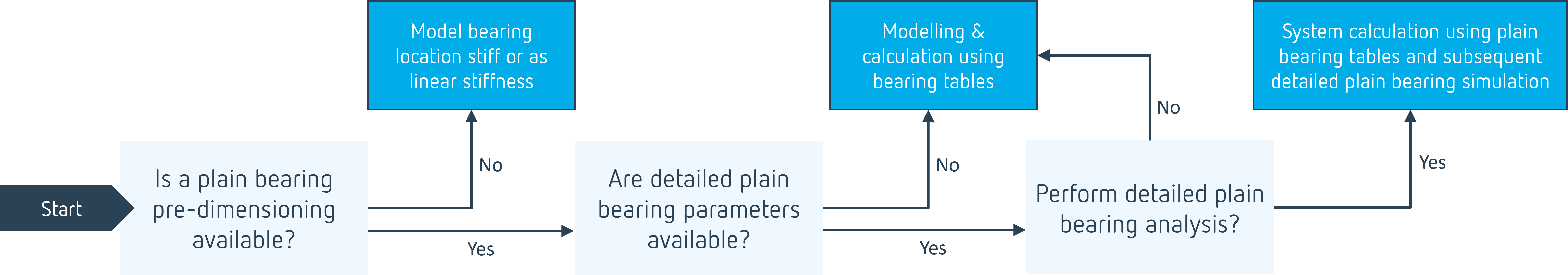
Orientation - when to use each calculation method
When "plain bearing table" is selected, the operating behavior is approximated based on predefined dimensionless tables, assuming the validity of the simulation theory. These tables were developed in FVA Research Project FVA 668 II based on DIN 31657. In many cases, this variant is a good compromise between calculation speed and accuracy.
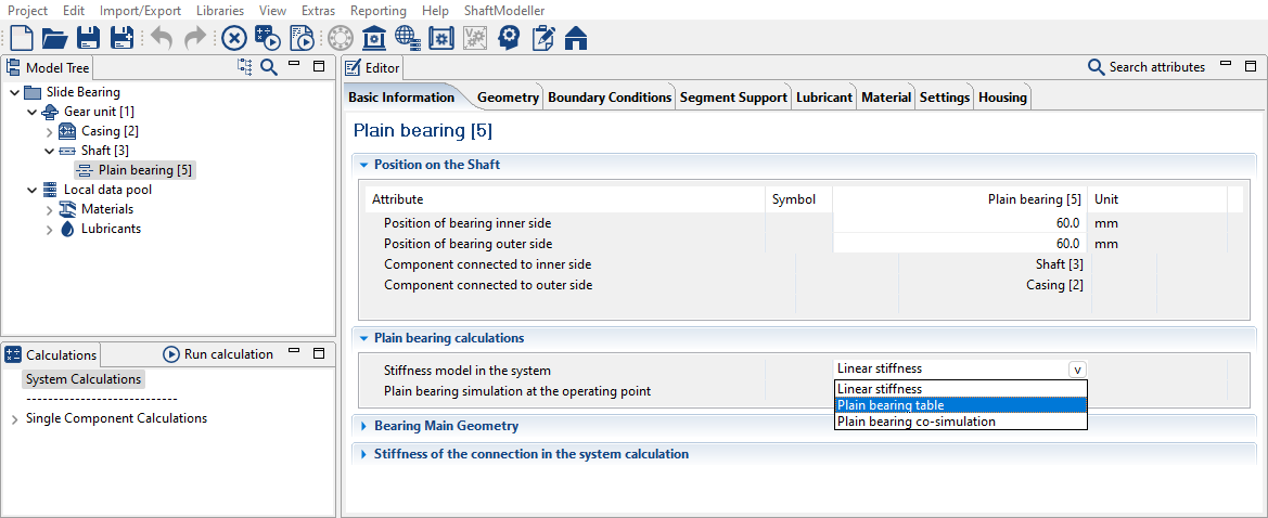
Under "stiffness model in the system," you can now select the level of detail with which the bearing stiffness should be considered in the system iteration individually for each plain bearing.
Bolt calculations are an essential element of gear design. The required bolt dimensions, strength class, and preload force are key for every flange connection.
This new calculation module makes it simple to design bolt connections and perform strength calculations. With the preliminary design according to VDI 2230, a recommended bolt diameter can be calculated based on just a few parameters such as the load type and maximum axial force.
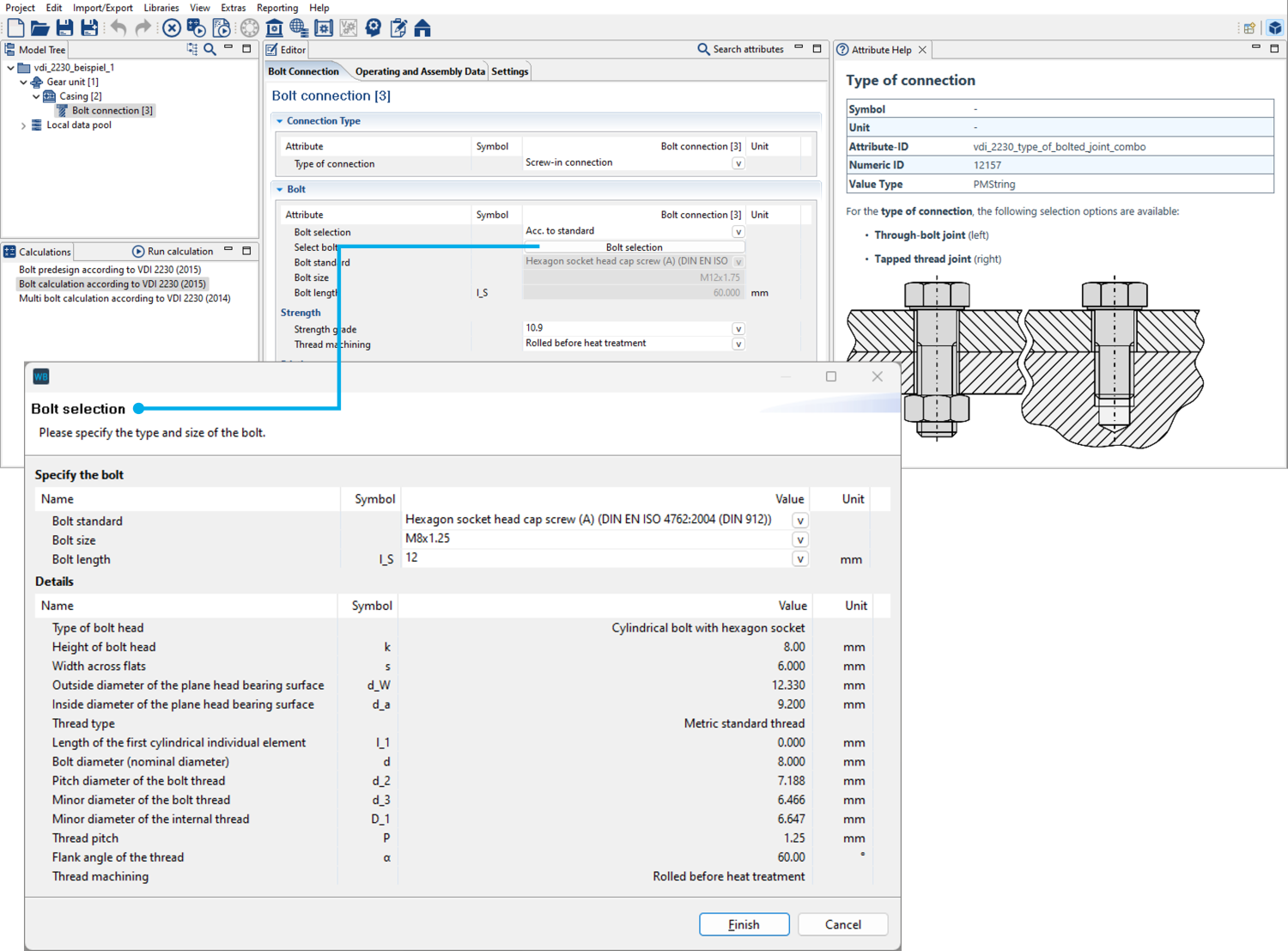
Bolt parameters can be specified in the Editor. A large number of standard bolts can also be selected.
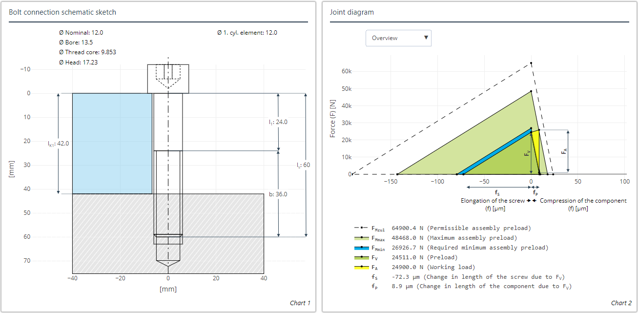
Schematic and joint diagram of the bolt connection from an FVA-Workbench output report
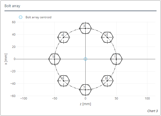
Multi bolted joints can also be calculated. The bolt arrays can be rotationally symmetrical or specified in an XZ-coordinate system.
FE-based notch calculations
FE-based calculations can be used to determine the stress concentration factors for the following notch configurations:
Notch | Nominal | FE-based |
|---|---|---|
Feather key connection | ✓ | - |
Transverse bore | ✓ | - |
Transverse press connection | ✓ | - |
Rectangular groove | ✓ | ✓ |
Round groove | ✓ | ✓ |
V-shaped groove | ✓ | - |
Serrated shaft | ✓ | - |
Splined shaft | ✓ | - |
| - | ✓ |
Shaft shoulder | ✓ | ✓ |
| - | ✓ |
| - | ✓ |
Shaft shoulder with undercut | ✓ | ✓ |
| - | ✓ |
| - | ✓ |
Splined shaft with involute splines | ✓ | - |
Smooth shaft | ✓ | - |

Hollow shaft shoulder | Hollow shaft shoulder with undercut | Gear on shaft shoudler | Shaft shoulder with undercut gear | Shaft shoulder with undercut and undercut gear |
 |  | 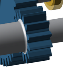 | 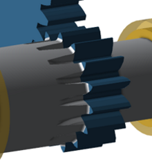 | 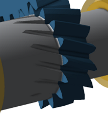 |
The type of stress concentration factor calculation (nominal or FE-based) can now be specified individually for each notch in the Editor.
The notch mesh can also now be visualized, including the clamping, load introduction, and evaluation point.
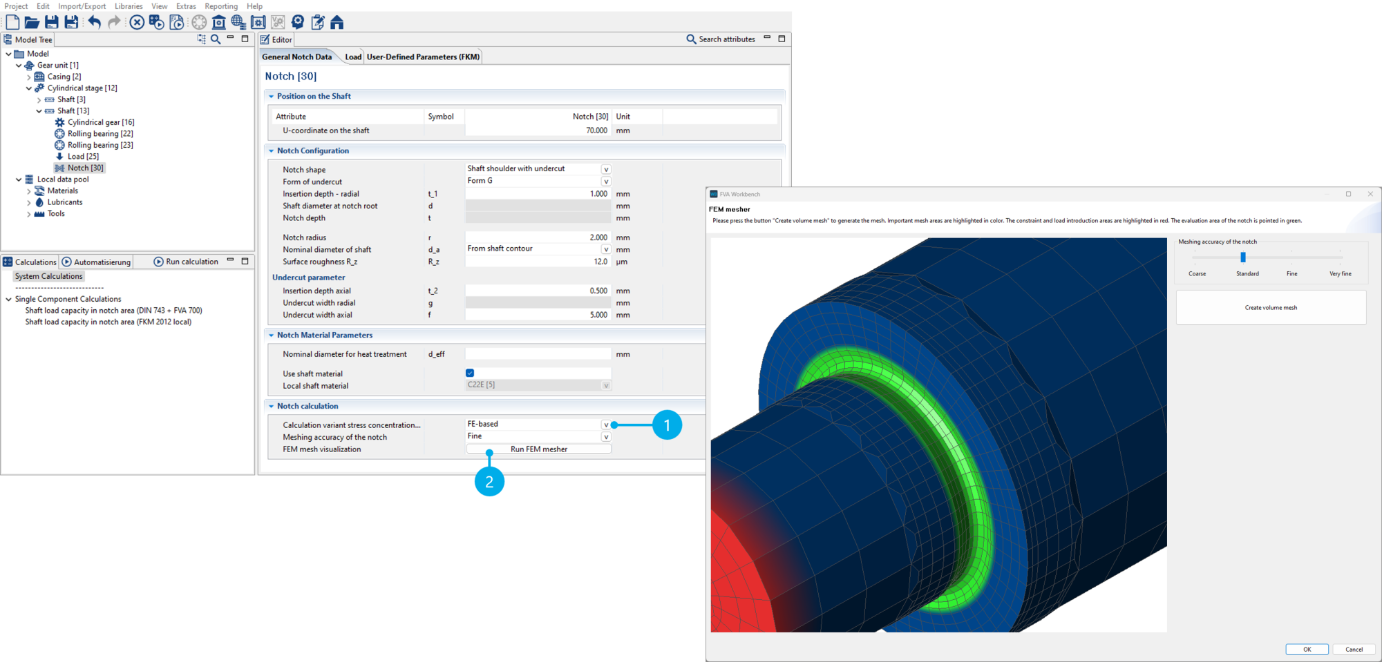
Selection of the stress concentration factor calculation method (1) and visualization of the notch mesh (2)
New chart: tooth space geometry
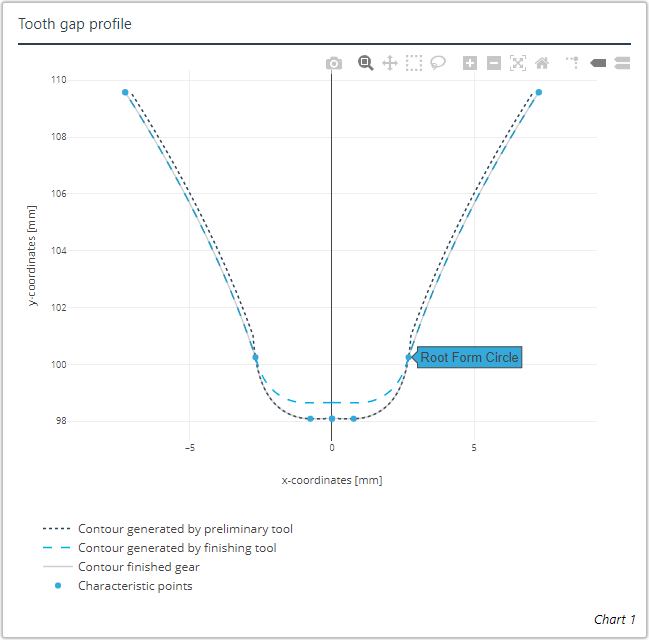
The contours generated by the roughing and finishing tools are superimposed in this new chart. Characteristic points such as the transition from the tooth flank to the tooth root are also shown.
Links to attribute help in output reports
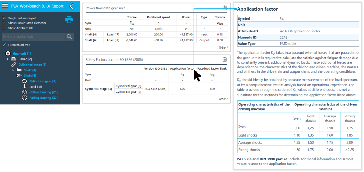
Clicking on the attribute name in output reports opens the corresponding attribute help in a new browser tab.
Adjustments to plain bearing bore geometry chart
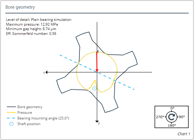
The mounting angle and level of detail of the calculation (simulation or plain bearing table) are now shown in the plain bearing bore geometry chart.
Cylindrical gears
The following output attributes have been added for preliminary gearing:
Tip diameter, attribute ID "stplus_result_tip_diameter_with_preliminary_tool"
Root diameter, attribute ID "stplus_result_root_diameter_with_preliminary_tool"
Addendum form diameter, attribute ID "form_diameter_of_addendum_with_preliminary_tool"
Dedendum form diameter, attribute ID "form_diameter_of_dedendum_with_preliminary_tool"
The single stiffness c' (attribute ID "iso 6336 single stiffness") can now be calculated and output for individual cylindrical gear stage calculations according to VDI 2736.
The "ductile (with pronounced yield strength)" deformation behavior option was added for the material properties. This specification is only used for calculation of the factor YdrelT,static (ISO 6336-3). For all other calculations, the deformation behavior of the material is considered as ductile.
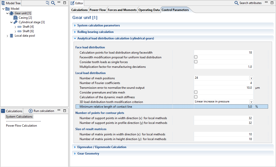
The minimum relative contact line length can now be specified. This defines a percentage of the contact width above which the length of the short contact lines at the start and end of the mesh of helical gears can be kept constant. This can mitigate computational stress peaks in these areas. The maximum permissible area is 10% of the contact width. By specifying this value, the load-reducing effect of local plasticizing or local limited surface break-outs can be considered in these areas.
Rolling bearings
The standard calculation method for rolling bearings is now set to "FVA 909" during a model upgrade. This primarily affects older models for which "FVA 364 (FVA LAGER2 calculation kernel)" is selected as the calculation method. Calculation according to FVA 364 will no longer be supported in future versions. FVA 364 can still be selected in FVA-Workbench 8.1 for comparison purposes. For more information, see rolling bearing calculation documentation.
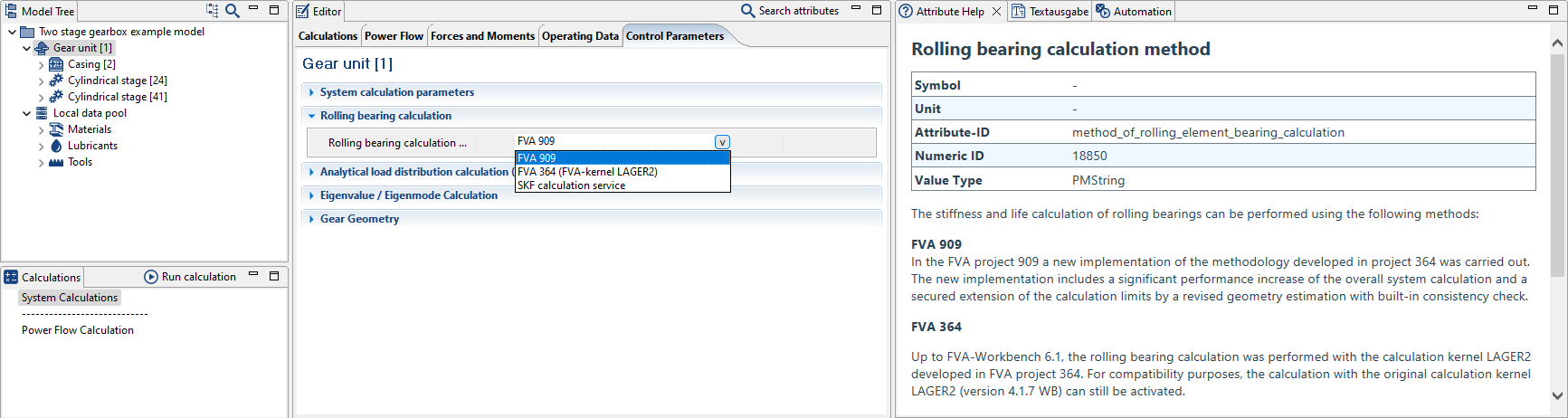
A note about the change to the calculation method is displayed during the model upgrade.
The SKF bearing database has been updated.
The "calculate combined planet bearing rating life" option is new.
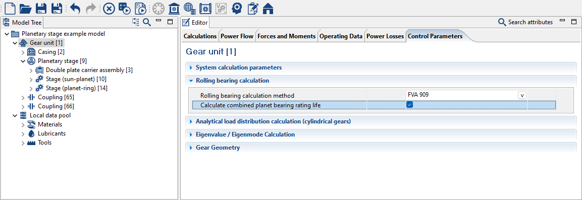
When this switch is activated, the calculated bearing rating life for each position of the planets is combined to a total rating life. With 3 or more planets, the combined rating life only deviates slightly from that of the rating life calculated for the entire rotation. In this case, the static safety is calculated for the bearing with the highest load.
The convergence behavior for nearly unloaded bearings with clearance has been improved.
Bevel gears
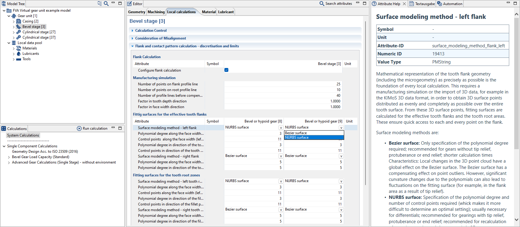
NURBS surfaces can now also be used as an alternative to Bezier surfaces for mathematical description of the tooth flank and root areas in local calculations. NURBS surfaces are configured by specifying the polynomial degree and the number of control points. The NURBS surface approach is particularly advantageous for gears with relief (tip relief, end relief, protuberance), forged differentials (complex root geometry characterized by strong changes in the toe and heel area), and recalculation of gear damage specified via 3D measurement data.
The bevel gear design according to ISO 23509 has been improved. Values are suggested for the cutting head diameter, number of cutting heads, nominal pressure angle, cutter module, tool tip routing, and more.
Shaft-hub connections
Tapered interference fits: the maximum joint diameter can now optionally be automatically determined from the shaft contour.
Tapered interference fits: the formula for the transmissible bending moment has been improved.
Tapered interference fit: the influence of centrifugal force on the tangential stress is now considered.
Couplings
Single-sided axial force absorption can now be specified for couplings:
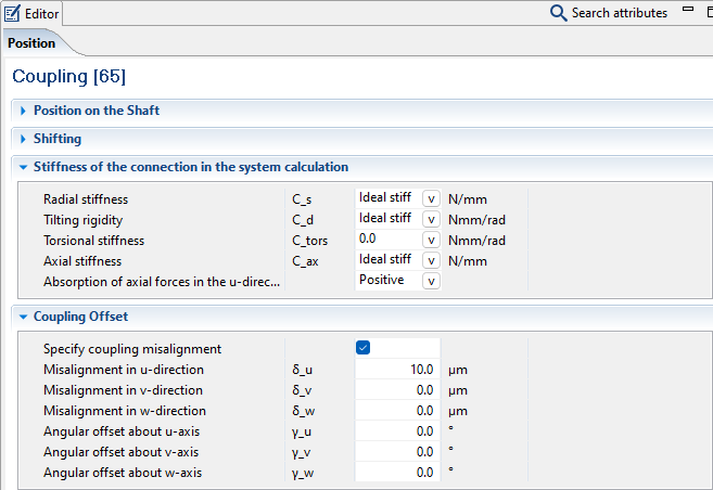
In combination with the option to specify an axial offset, a single-sided axial clearance can also be defined in addition to preload travel.
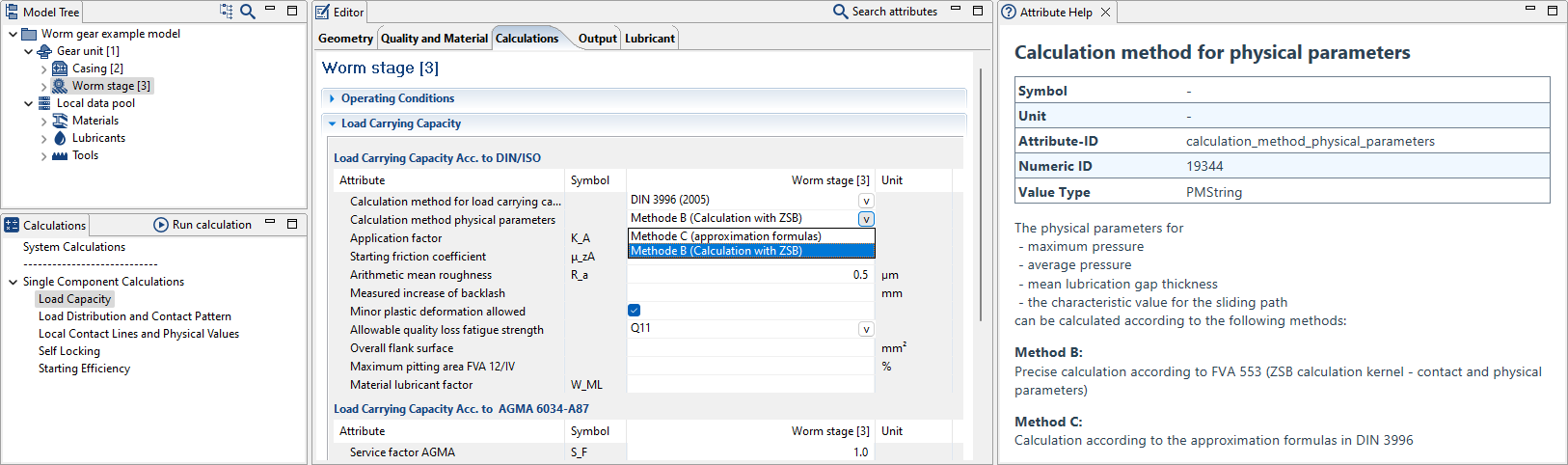
Worm stages
In the worm gear calculation, physical parameters can now be transferred to the load capacity calculation.
Power flow
The system load capacity calculations can be performed with either the nominal or actual resulting torques. When loading models, the new default value of "consider actual torques for calculations" is set and a warning is issued. This can be changed back to "calculate with nominal torques" at any time.

The actual torques are used by default for the load capacity calculations and the local methods. These result from the load distribution (with power splitting and merging) and from consideration of torque losses (when the power loss calculation is activated). If the "consider nominal torques for calculations" switch is activated, the nominal torques (with uniform load distribution and without consideration of losses) are used for the load capacity calculations and local methods. In this case, the component deformations are still calculated based on the actual torques calculated in the system.
FE meshing
The options for displaying and parameterizing FE meshes have been revised:
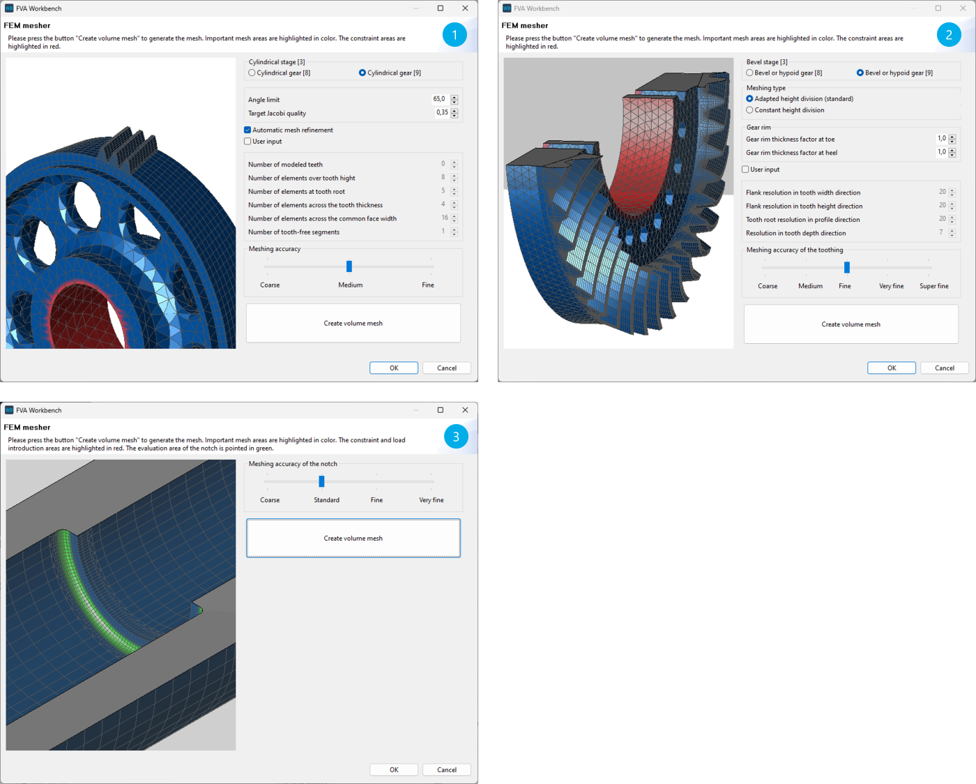
The new illustrations for the meshing of cylindrical and bevel gears (1,2) allow for better control of the settings and meshing parameters. The clamping areas are visually highlighted.
Notch meshes (3) can now also be visualized. The clamping, load introduction, and evaluation point are all shown.
Other
A descriptive error message has been added in the event that there is not sufficient storage available to save a model.
The loading time for models with several gear stages has been significantly reduced.
The attribute overview has been revised:
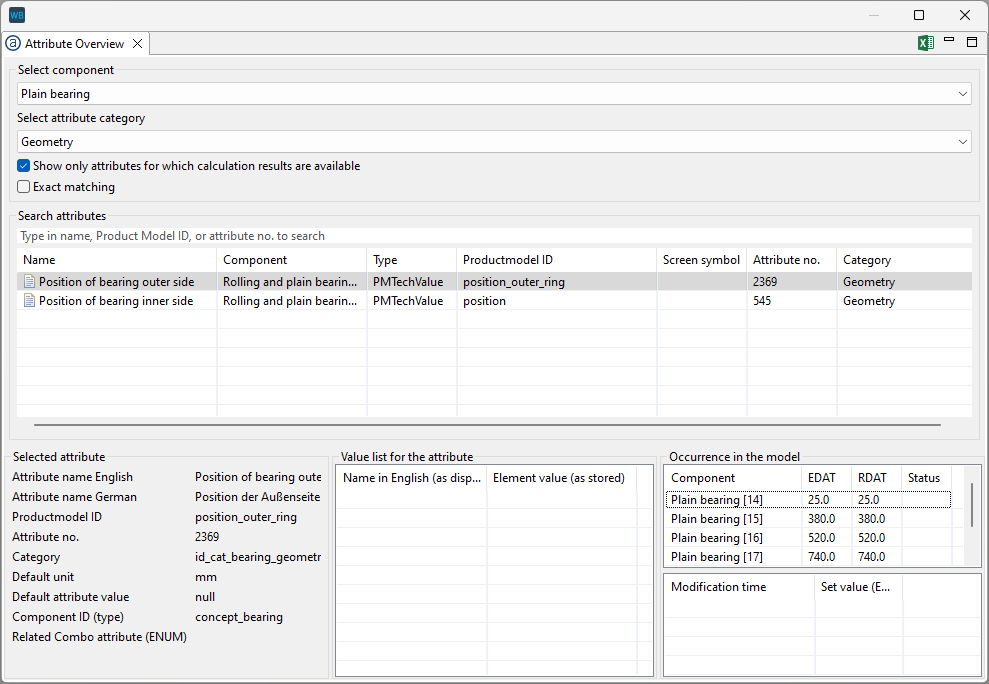
It is now possible to only show the attributes for which calculation results are available in the attribute overview. Furthermore, "exact matching" can also be used to limit the search results for attributes with similar names.
3D Model
The standard graphics driver has been changed to DirectX11 for smoother operation.
The left flanks of gears can now be highlighted in color in the 3D Model.
Scripting
New scripting function: getWorkbenchInfo()
Bugfixes
Bugfix: tools with displacement of the design line b_z0 are now calculated correctly.
Bugfix: corrected an error in the conversion to the modification amount when a flank line modification is specified in angular degrees.
Bugfix: corrected several errors in the wear calculation according to Plewe.
Bugfix: corrected an error where unrealistically high temperatures may have been output in the scuffing calculation according to DNV
Bugfix: corrected an error where the introduction of the loss torque to the tooth center led to a pressure peak in the load distribution with the power loss calculation activated.
Bugfix: corrected an error where a gap was shown in the 3D representation of bevel gears with simplified geometry in combination with a wheel body.
The local damage accumulation calculation is now performed without calculation of the nominal load case. The local load capacity of the load case with the maximum torque is shown in the output report.
Bugfix: corrected an error when importing large load spectra into the Global Database.
Bugfix: both "," and ";" are now recognized as separators when reading .csv files.
Bugfix: the speed is now taken from the power flow for the calculation of press fits.
Bugfix: corrected an error in specifying the utilization in tapered interference fits.
Bugfix: corrected a unit in the power loss calculation of axial plain bearings.
Bugfix: the color scale only referred to the pressure on the inner ring in the diagrams for the Hertzian stress of rolling bearings. The color scale is now displayed for both the inner and outer rings.
Bugfix: images from the 3D Model are now displayed in reports created with the SimulationHub.