FEM Planet Carriers (CAD/FEM)
This tutorial will demonstrate the process for importing a CAD/FEM planet carrier and connecting it to the gear model.
The following files are needed to follow along with this tutorial in the FVA-Workbench:
Load the model and import the CAD/FEM planet carrier
Load the model
Load the startPointPlanetCarrierImportTutorial_WB71.wbpz gearbox model.
Select the planet carrier component
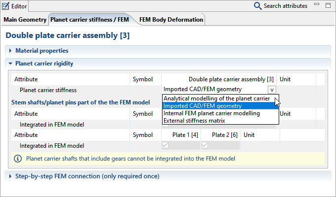
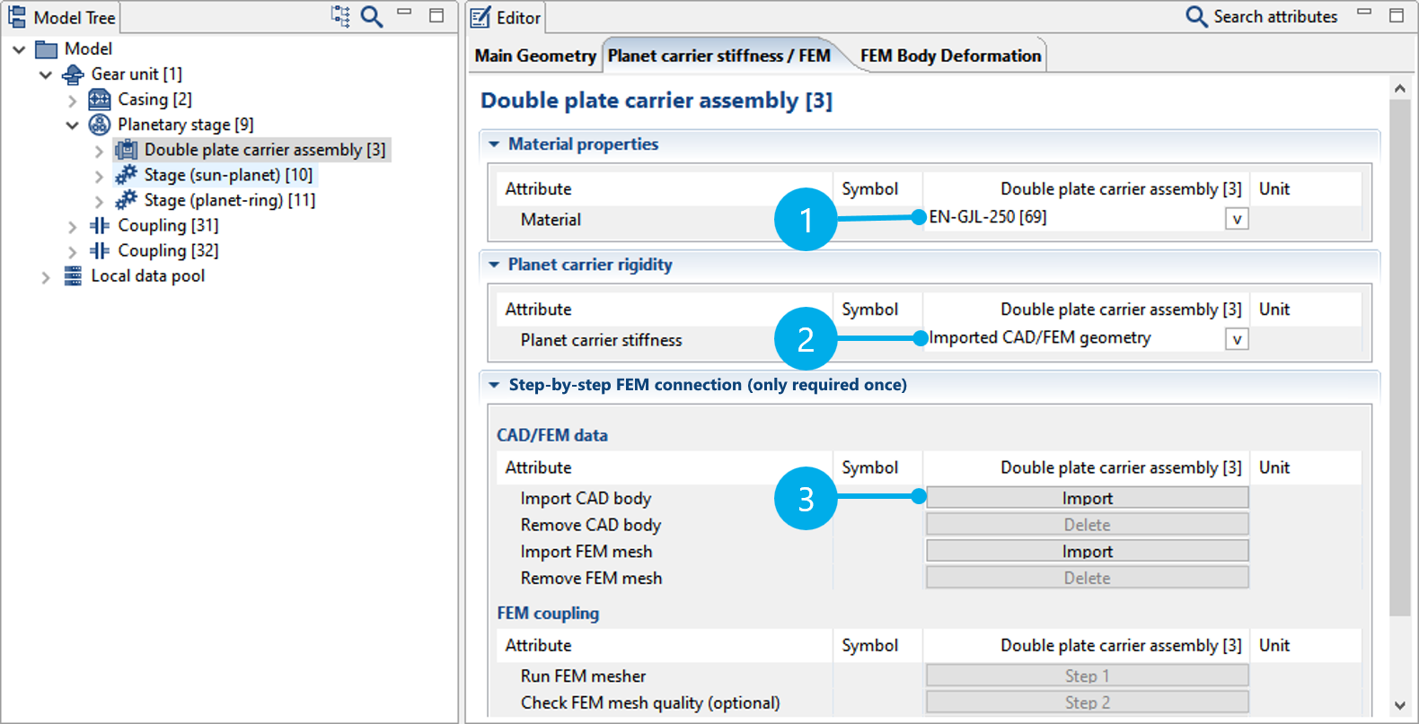
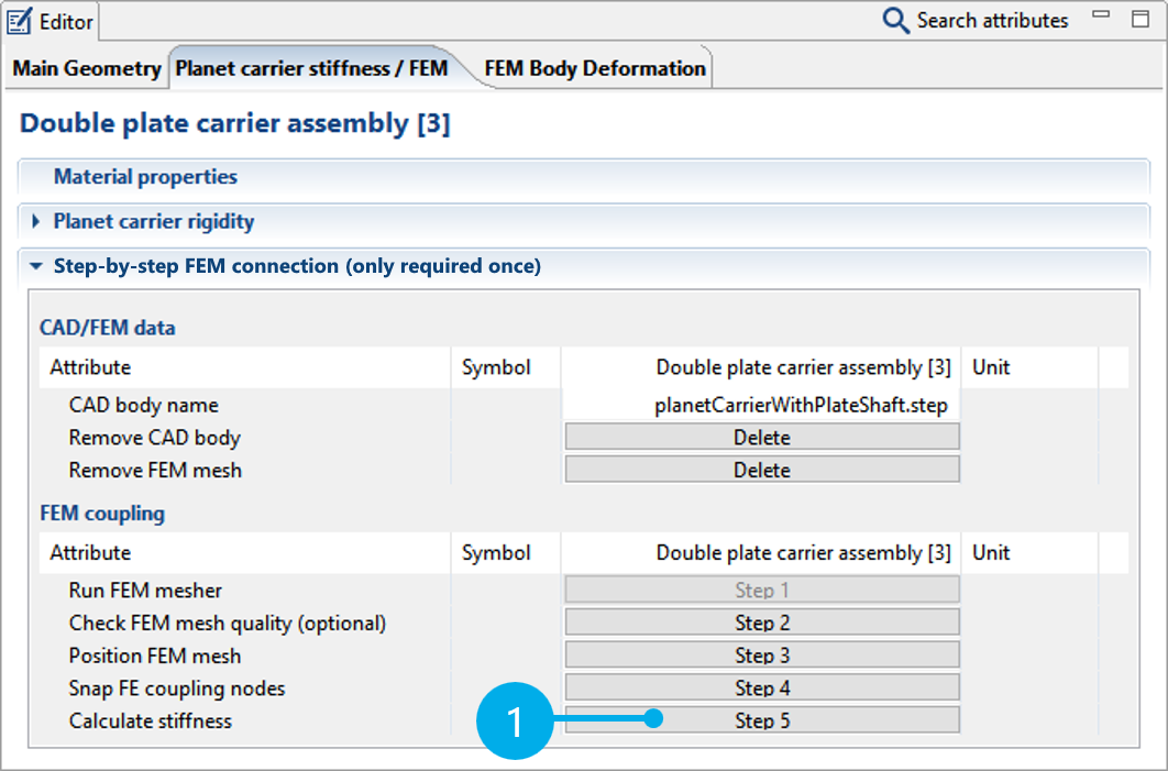
Select the dual-plate carrier assembly [3] in the Model Tree and switch to the "Planet carrier stiffness/FEM" tab in the Editor.
Select a suitable material for the planet carrier (1).
Select "Imported CAD/FEM geometry" from the planet carrier stiffness pull-down menu (2).
Import the CAD geometry
Now, import the CAD geometry for the planet carrier (3). To do so, select the planetCarrierWithPlateShaft.step file.
Notice
The planet carrier can also be imported as an FEM mesh.
In this case, FEM meshing is not required and "Step 1" is grayed out in the following steps.
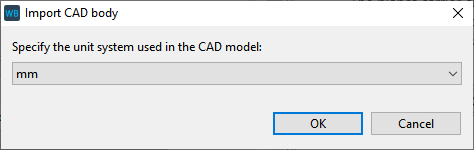
Select the unit in which the CAD geometry was designed. In this example, you can use the default selection of "mm" and click "OK" to close the dialog.
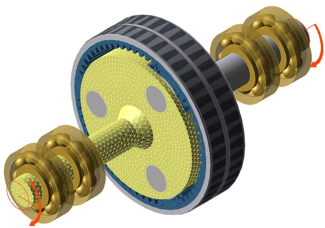
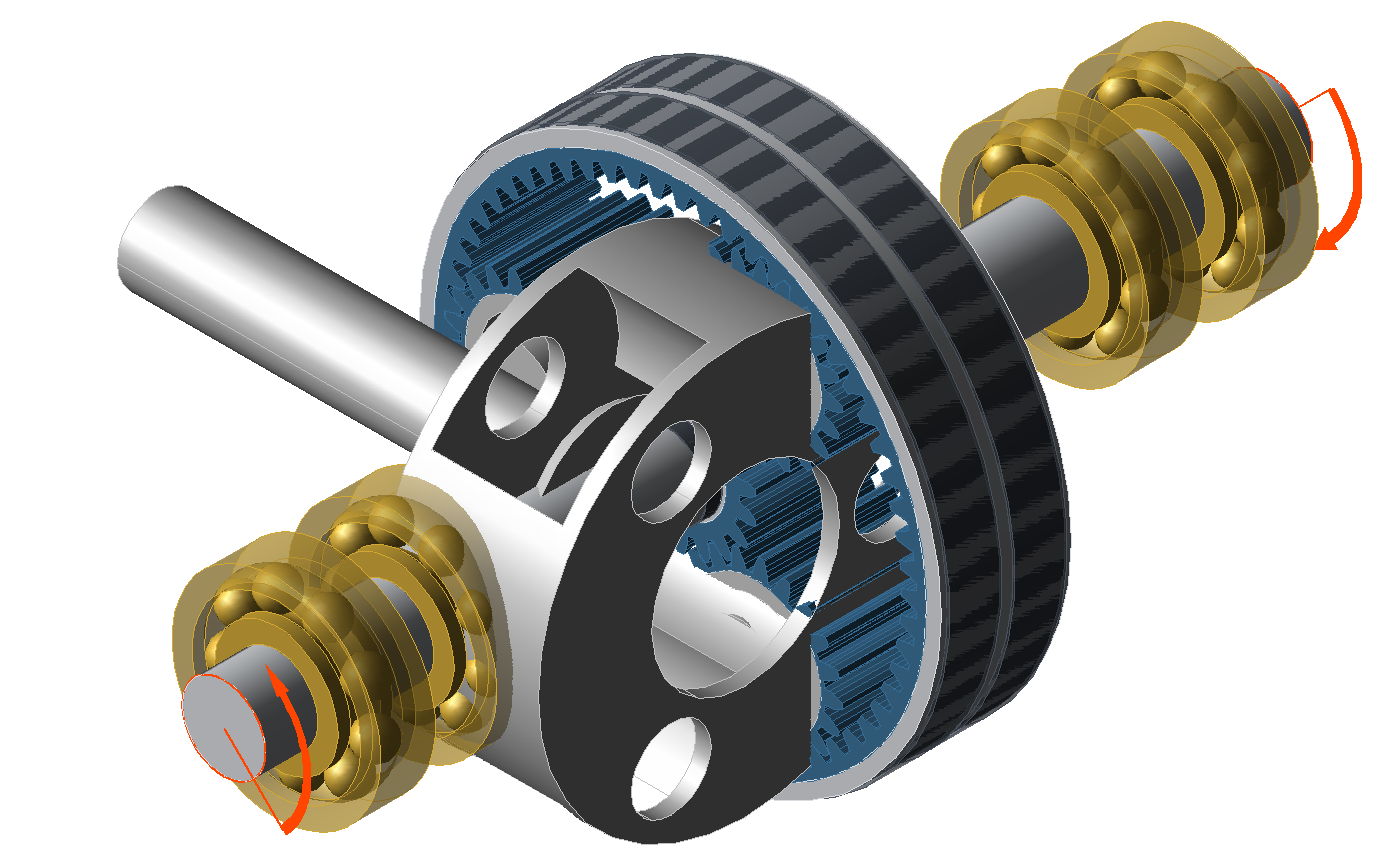
The planet carrier geometry is initially positioned in space independent of the gear model. If the coordinate system of the selected CAD design matches the gears' coordinate system, the initial position will be correct. However, this is not required. As this tutorial demonstrates, the positioning can be adjusted in a few simple steps.
FEM connection
The following section describes the five FEM connection steps, which are required to link the planet carrier geometry with the gear model.
Step 1: run the FEM mesher
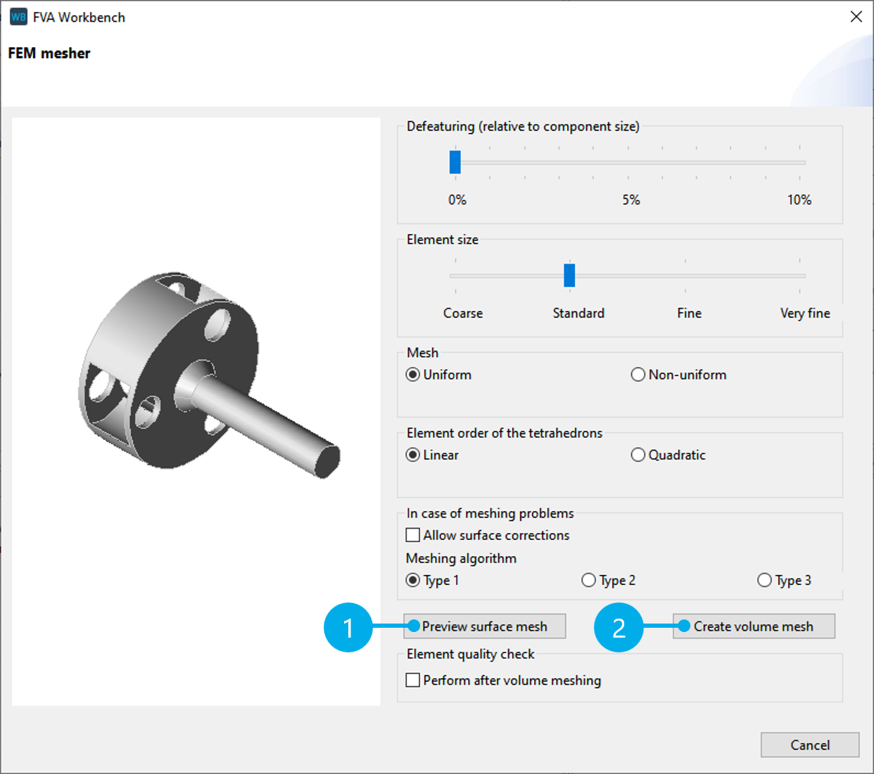
Step 1 ("Run FEM mesher") performs the FEM meshing of the CAD geometry. For more information, see Mesher.
The default meshing parameters can be used for this tutorial. Click "Preview surface mesh" (1) for a preview. If the meshing of the surface is adequate, click "Create volume mesh" (2) to complete the meshing process.
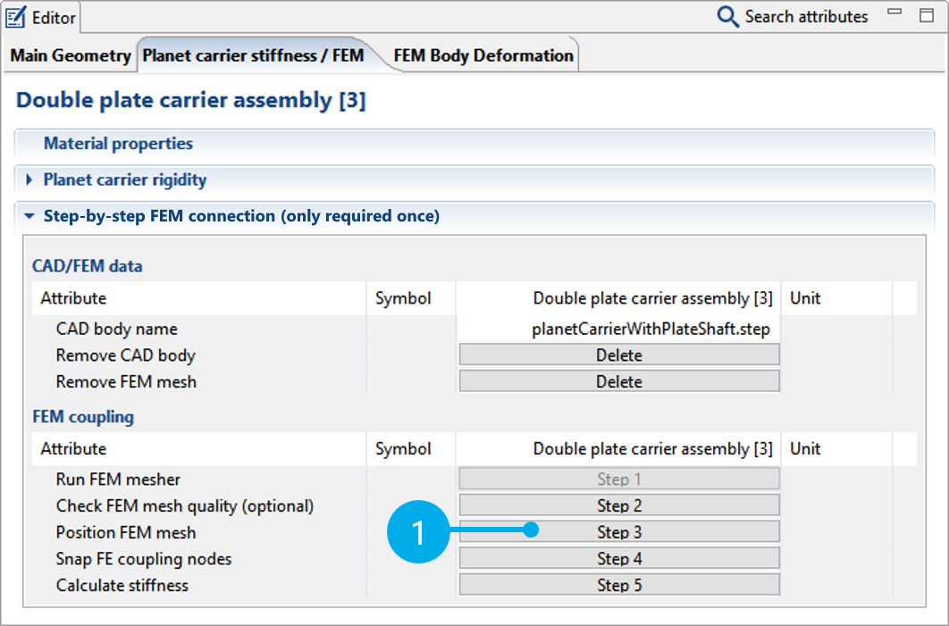
Step 3: positioning
The positioning of the planet carrier FEM mesh is performed in Step 3 ("Position FEM mesh").
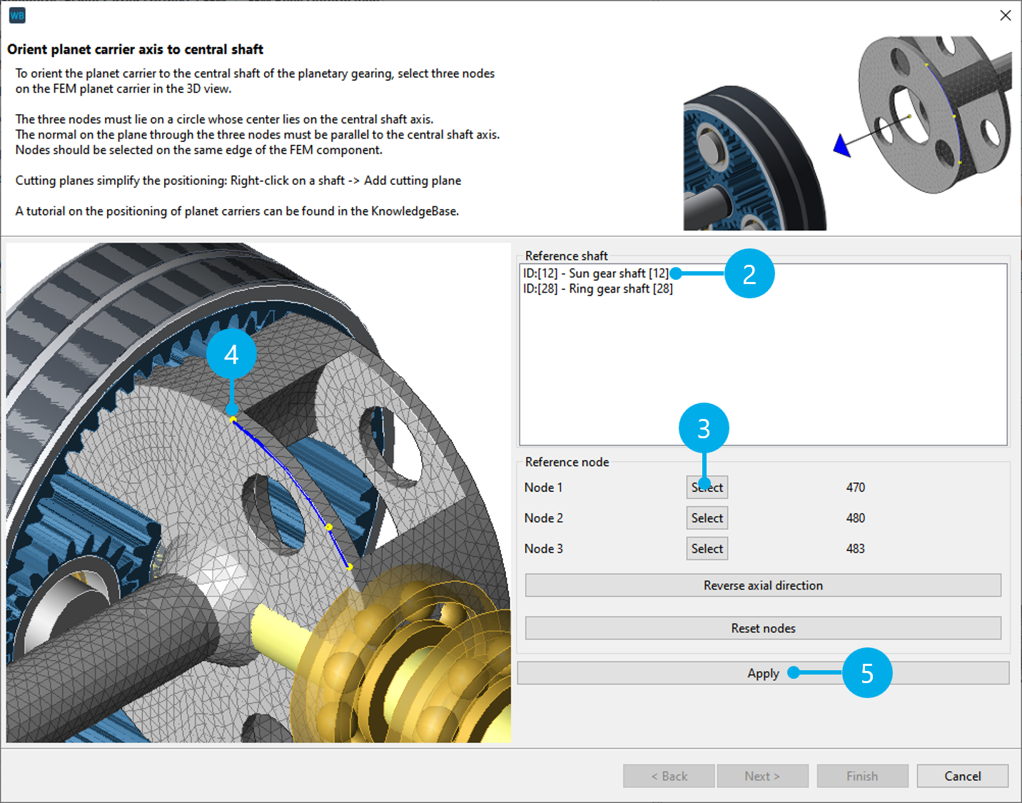
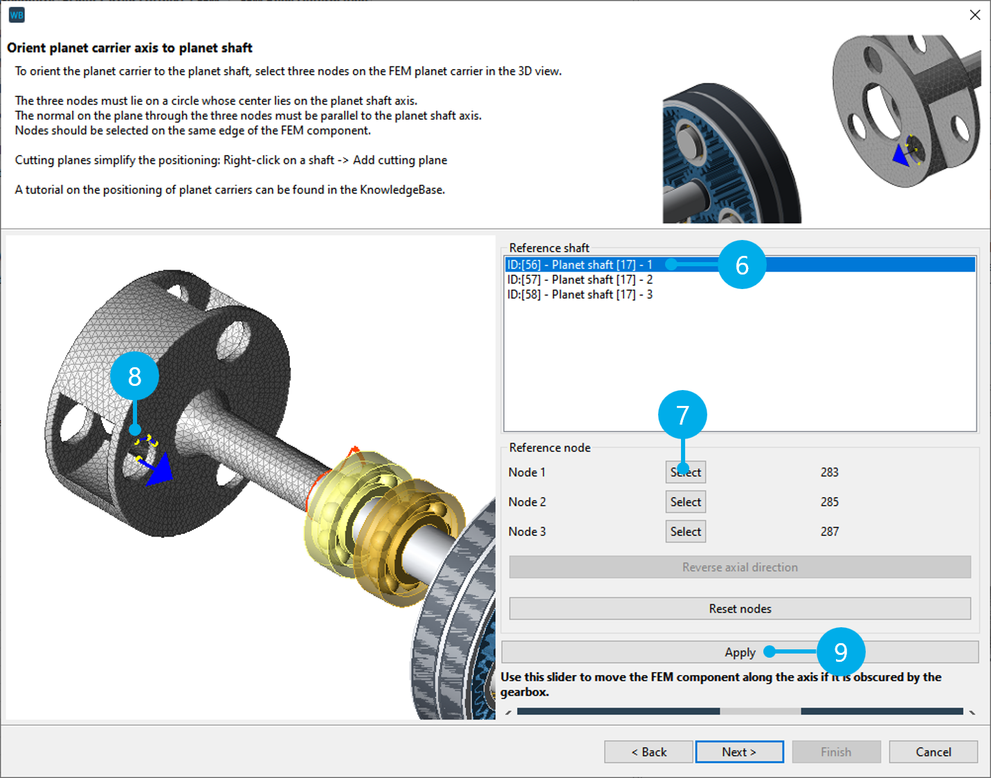
Orient the planet carrier mesh to the central shaft of the planetary gear
Select one of the two central shafts as the reference shaft (2). Next, click "Select" (3) and select a node in the 3D Model (4). Perform this step 3 times (for Node 1, Node 2, and Node 3) to select a total of 3 reference nodes.
To correct an FE node, click "Select" again and choose a different FE node in the 3D Model.
Click "Apply" (5) to orient the reference shaft, then click "Next" to complete the positioning of the first reference shaft.
Notice
The three nodes must span a circle whose center corresponds to the center of the central shaft axis. The normal on the plane through the three nodes must point in the direction of the central shaft axis. Ideally, the nodes should be on an edge of the FEM model.
If the planet carrier is seated the wrong way around in the planetary gear, click "Reverse axial direction."
If the gearbox obscures the planet carrier, the slider can be used to adjust the distance between the gear and the planet carrier mesh. This feature is only to provide a better overview; it does not affect the positioning.
Orient the planet carrier mesh with the carrier shaft of the planetary gear
Select one of the planet carrier shafts as the second reference shaft (6). Again, three nodes must be selected on the FEM planet carrier (see 7, 8). The nodes should be selected so that the center of the circle corresponds with the center of the selected planet carrier shaft axis.
Click "Apply" to complete the positioning of the second reference shaft (9).
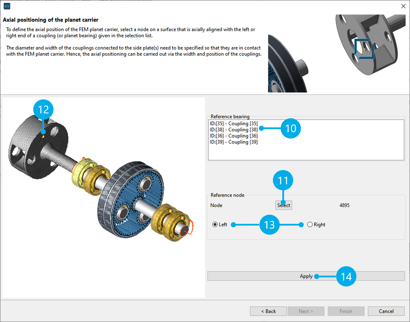
Axial positioning of the planet carrier mesh
The axial position of the planet carrier is determined in the next step. To do so, the axial position of an FE node (11, 12) is oriented with the left or right end of a coupling from the selection list (10) of all couplings and bearings that are connected with the plate.
"Left" and "Right" (13) are used to specify which end of the coupling to align.
Notice
Accurate dimensioning of the couplings that come into contact with the FE planet carrier is essential for the positioning and for snapping the coupling nodes.
The inner and outer diameters are particularly important, along with the width and position.
Click "Apply" to orient the axial position of the planet carrier (14), and then click "Finish" to complete the positioning of the planet carrier mesh.
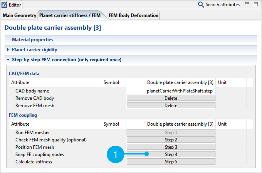
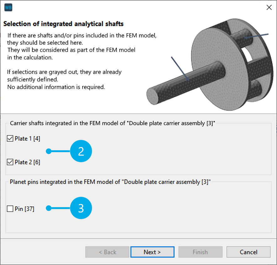
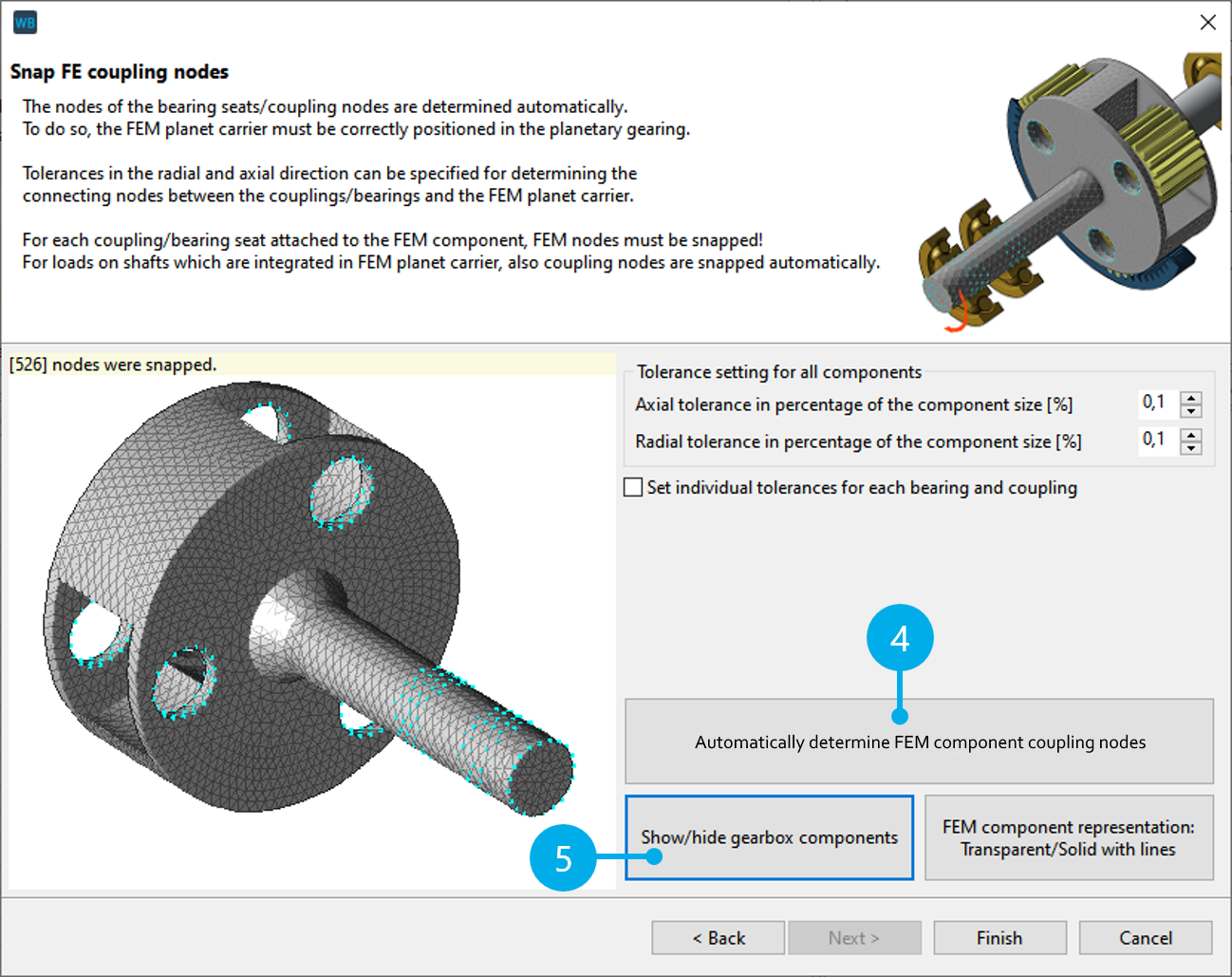
Determine the FE coupling nodes
Click Step 4 ("Snap FE coupling nodes") to open a two-step dialog for snapping the coupling nodes.
First, the shafts that are part of the FE mesh are selected. No separate analytical calculation (Timoshenko beam) is performed for these shafts. There are no default selections; the correct shafts must always be selected. The selection includes the planet carrier shafts (2) and the planet pins (3). For this tutorial, select the two carrier shafts.
Next, click "Automatically determine FEM component coupling nodes" (4) to automatically snap the coupling nodes between the FE planet carrier and the analytical gearbox. Click (5) to hide the gearbox and review the snapped nodes. Individual axial and radial tolerances for snapping the nodes can be specified for each component, if necessary.
Determine the stiffness
Click Step 5 ("Calculate stiffness") to perform the stiffness calculation. The calculated reduced stiffness matrix is saved in the model file (*.wpbz) and used for all subsequent calculations.
Different planet carrier stiffness options can be selected from the drop-down menu to enable comparisons with the "Analytical modeling of the planet carrier."