FEM Shafts
This tutorial will demonstrate the process for importing a CAD shaft and connecting it to the gear model.
The following files are needed to follow along with this tutorial in the FVA-Workbench:
Notice
It is important to determine whether a CAD component should be imported as a shaft or wheel body. The difference is not always clear, depending on the CAD model. The determining factor is as follows: if a component is connected to more than a gear (e.g., coupling, load, etc.) it must be imported as a shaft.
Import the CAD shaft
Load the model
Load the FEM-shaft-tutorial.wbpz gear model.
Import the CAD geometry
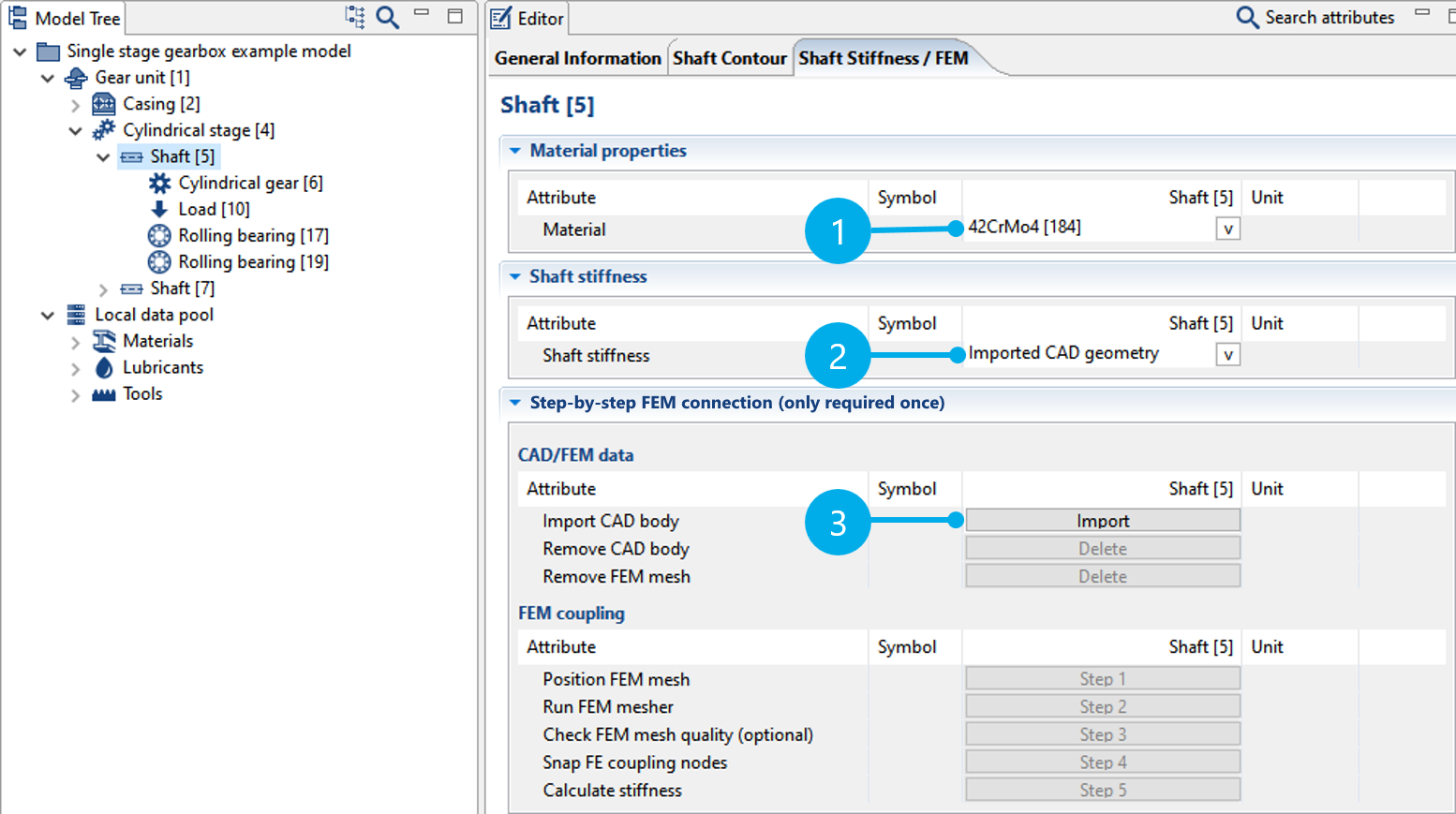
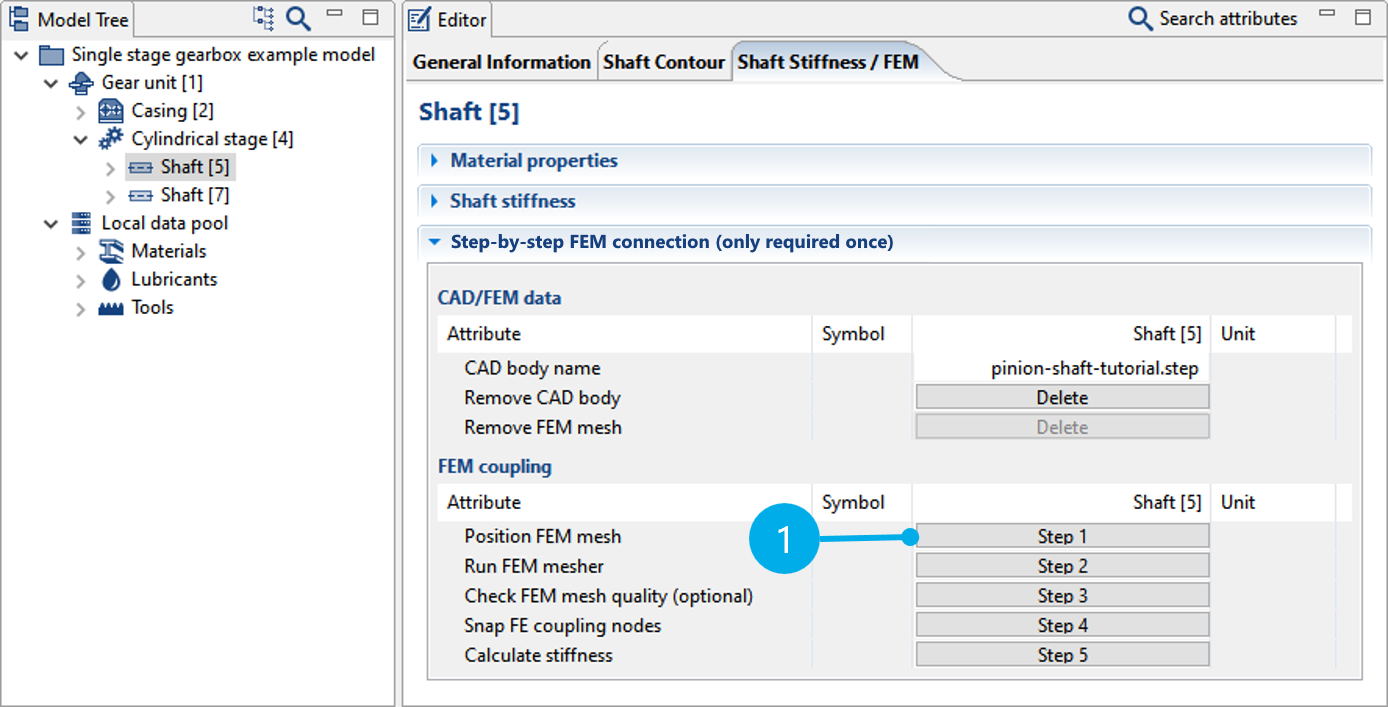
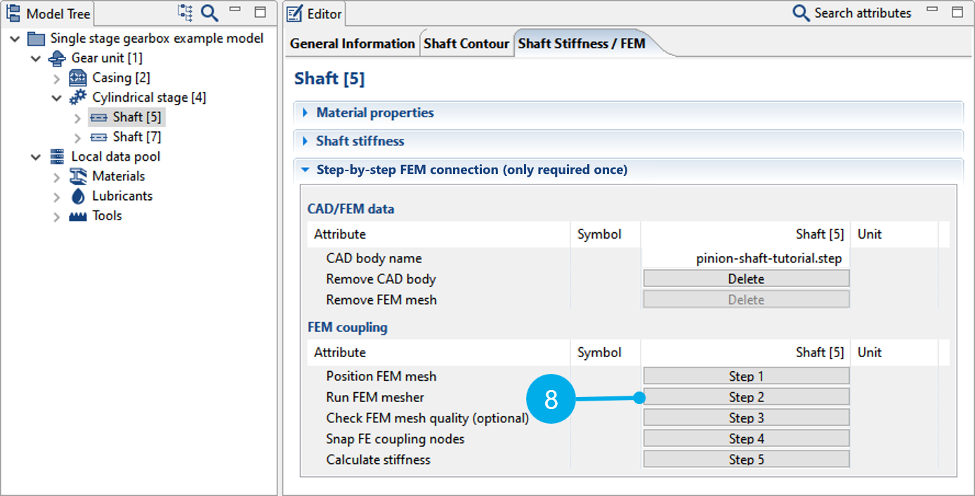
Select the Shaft [5] component in the Model Tree and switch to the "Shaft Stiffness/FEM" tab in the Editor.
Select an appropriate material for the shaft (1).
Select "Imported CAD geometry" from the shaft stiffness pull-down menu (2).
Click (3) to import the CAD geometry for the shaft; select the pinion-shaft-tutorial.step file.
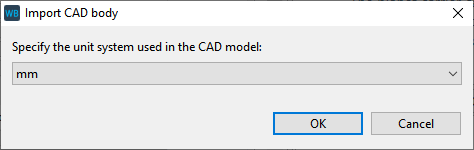
Select the unit in which the CAD geometry was designed. For this example, you can use the default selection of "mm" and click "OK" to close the dialog.
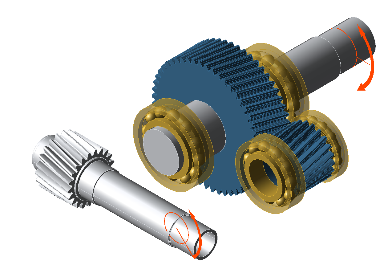
The shaft geometry is initially positioned in space independent of the gear model. If the coordinate system of the selected CAD design matches the gear's coordinate system, the initial position will be correct. However, this is not required. As this tutorial demonstrates, the positioning can be adjusted in a few simple steps.
FEM connection
The following section describes the steps for the FEM connection, which is required to link the shaft geometry with the gear model.
Step 1: position the FEM mesh
The imported shaft CAD geometry is positioned in Step 1 ("Position FEM mesh").
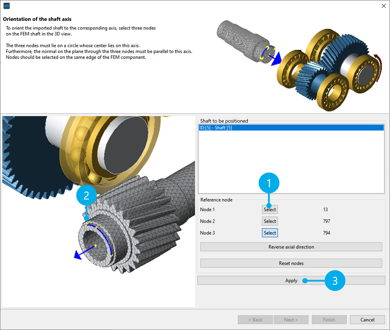
Orient the shaft axis
A temporary surface mesh is laid over the shaft so that the standard positioning procedure can be used. Click "Select" (1) and select a node in the 3D Model (2). Perform this step 3 times (for Node 1, Node 2, and Node 3) to select a total of 3 nodes.
Notice
The three nodes should span a circle whose center corresponds to the center of the shaft axis in the gear model. The normal on the plane through the three nodes must point in the direction of the shaft axis in the gear model. Ideally, the nodes should be on an edge of the FEM mesh.
To correct an FE node, click "Select" again and choose a different FE node in the 3D Model.
Click "Apply" (3) to orient the shaft, then click "Next" to complete the step.
If the shaft is the wrong way around, click "Reverse axial direction."
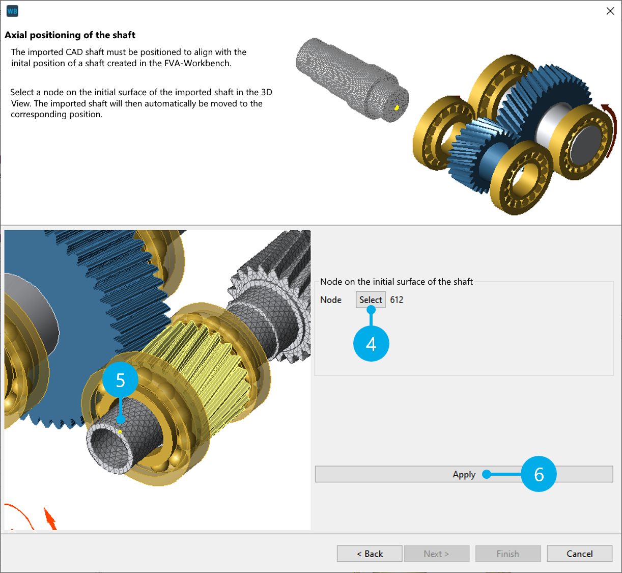
Axial positioning of the shaft
Next, the CAD geometry is positioned axially. The CAD geometry is oriented to the initial position of the analytical shaft in the gear model.
Click "Select" (4) and choose an FE node in the 3D Model (5) that lies on the starting surface of the CAD geometry. Click "Apply" (6) to position the FE mesh so that the selected nodes are located on the axial starting position of the analytical shaft.
Notice
The analytical shaft remains as the basis in the gear model, and the modeling (e.g., adding components) continues to be made on it. The analytical shaft can be simplified, but the following points must be kept in mind:
The initial position must correspond to the initial position of the CAD geometry of the shaft.
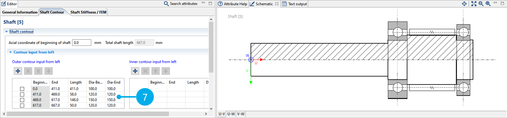
The contour and the associated diameter must be correct at connection points with other components (bearings, loads, seals, gears). In this example, this refers to the load, the two bearings, and the gear (7). At connection points with a gear, the diameter must be selected such that the CAD shaft geometry is cut along the entire gear width and simultaneously the diameter is below the root circle of the gear. This ensures proper connection with the gear.
Notch calculations (DIN743 and FKM) are also based on the analytical shaft contour. The loads (internal forces) are determined from the system calculation with the reduced stiffness matrix. The geometry data is taken from the analytical shaft contour, so it is important that the shaft shoulders, etc. are modeled correctly.
Step 2: run the FEM mesher
Click (8) to perform the FEM meshing.
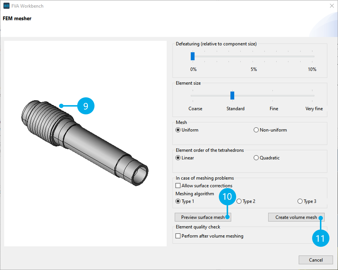
At connection points with a gear, the CAD geometry is cut as described above. The purpose of this is solely to verify that a cylindrical surface is available to connect the gear as required for the calculation (9).
For more information, see Mesher. The default meshing parameters can be used for this tutorial. Click "Preview surface mesh" (10) for a preview. If the meshing of the surface is adequate, click "Create volume mesh" (11) to complete the meshing process.
Step 3: check the mesh quality (optional)
Click Step 3 ("Check FEM mesh quality") to use the mesh quality checker to identify problematic elements.
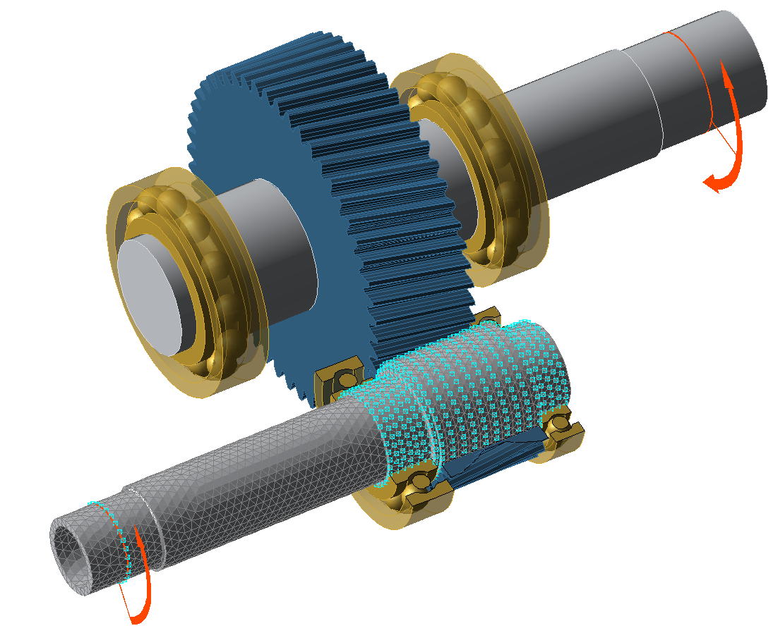
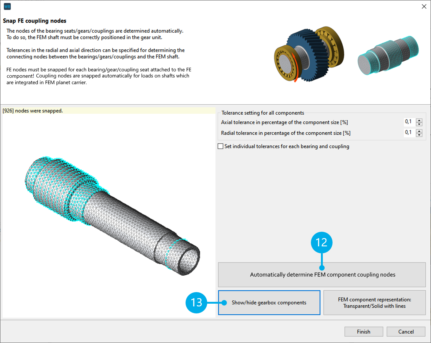
Step 4: determine the FE coupling nodes
Click (12) to automatically snap the coupling nodes between the FE shaft and the analytical gear model. Click (13) to hide the gearbox and review the snapped nodes. Individual axial and radial tolerances for snapping the nodes can be specified for each component, if necessary.
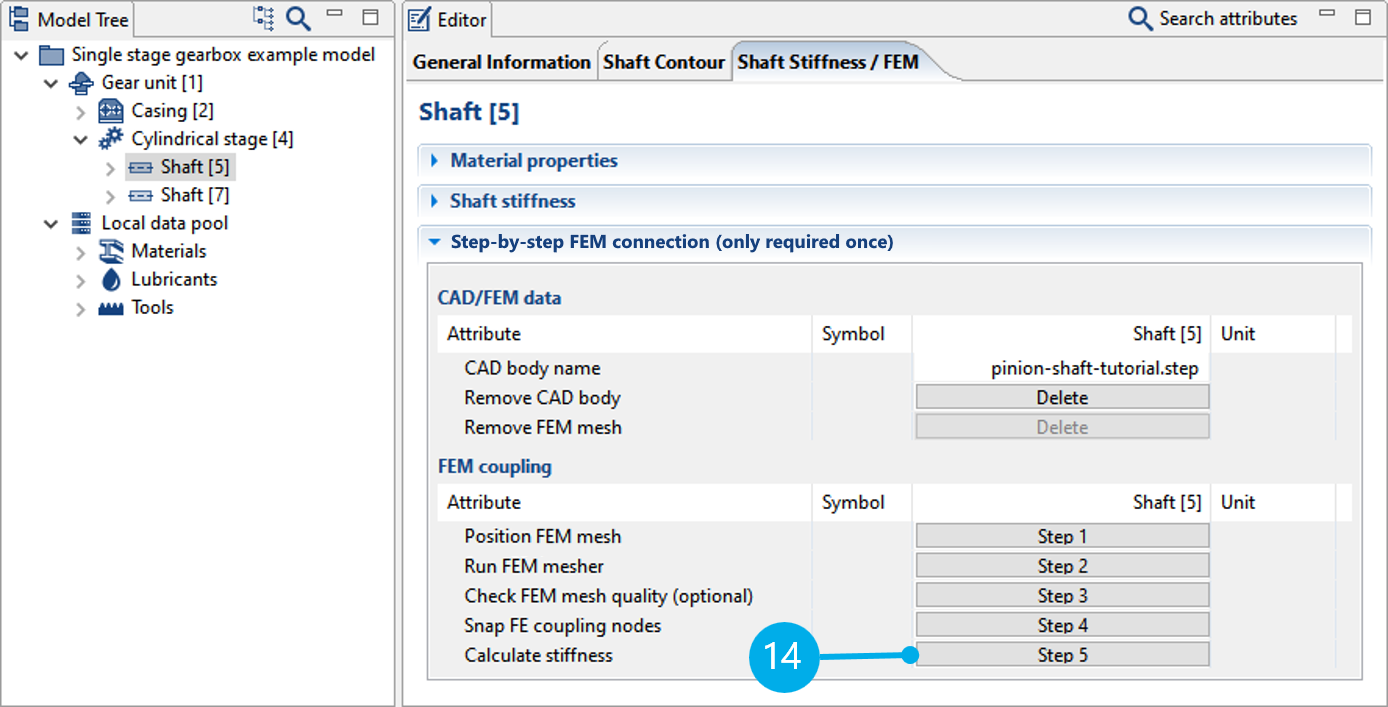
Step 5: determine the stiffness
Click Step 5 ("Calculate stiffness") to perform the stiffness calculation. The calculated reduced stiffness matrix is saved in the model file (*.wpbz) and used for all subsequent calculations.