DXF functions
The Drawing Interchange File Format (DXF) is a file format for exchanging 2D CAD data. Scripting in the FVA-Workbench includes a variety of features for programmatic control of shapes. Colors, text format, and line thickness can also be customized.
Functions for creating DXF shapes and text are all performed on one DXF object. Multiple DXF objects can be created in one script and exported to different files.
Example Draw a rectangle with a width of 10 and height of 20, starting with the coordinate origin (0, 0).
let dxf = new Dxf("MyDXF");
dxf.setLineWidth(1.0);
dxf.drawRect(0, 0, 10, 20);
dxf.export("C:\\example\\drawing.dxf");
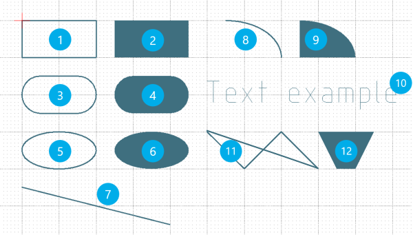
Number | Description | Function |
|---|---|---|
1 | Rectangle | dxf.drawRect(posX, posY, width, height); |
2 | Rectangle (filled) | dxf.fillRect(posX, posY, width, height); |
3 | Rounded rectangle | dxf.drawRoundRect(posX, posY, width, height, arcWidth, arcHeight); |
4 | Rounded rectangle (filled) | dxf.fillRoundRect(posX, posY, width, height, arcWidth, arcHeight); |
5 | Oval | dxf.drawOval(posX, posY, width, height); |
6 | Oval (filled) | dxf.fillOval(posX, posY, width, height); |
7 | Line | dxf.drawLine(posX1, posY1, posX2, posY2); |
8 | Arc | dxf.drawArc(posX, posY, width, height, startAngle, sweepAngle); |
9 | Arc (filled) | dxf.fillArc(posX, posY, width, height, startAngle, sweepAngle); |
10 | Text | dxf.drawString(string, posX, posY); |
11 | Polygon | dxf.drawPolygon(ArrayPosX, ArrayPosY, numberPoints); |
12 | Polygon (filled) | dxf.fillPolygon(ArrayPosX, ArrayPosY, numberPoints); |
13 | Poly line | dxf.drawPolyLine(ArrayPosX, ArrayPosY, numberPoints); |
Additional functions
Description | Function |
|---|---|
Set RGB colors for shapes and text | dxf.setColor(int Red, int Green, int Blue); |
Set line thickness | dxf.setLineWidth(linewith); |
Text size | dxf.setFontSize(int fontsize); |
Export DXF file | dxf.export(path); |
Examples
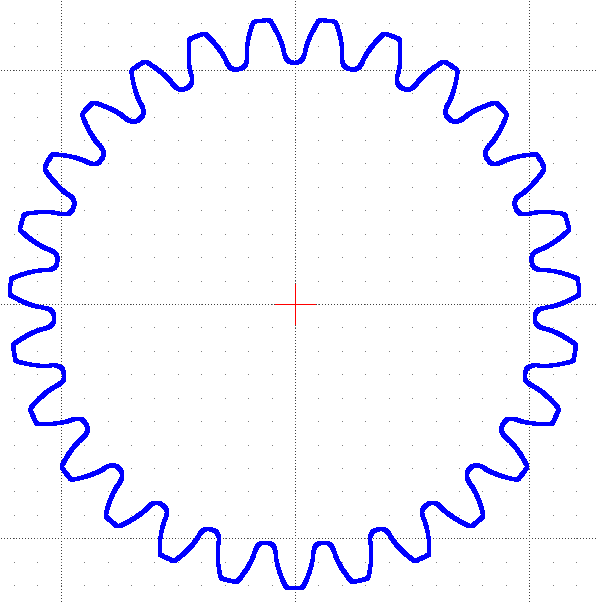
Exporting a gear as .dxf
A result of the FVA-Workbench geometry calculation is the tooth contour as a polyline. The x and y coordinates are saved separately in the cylindrical gear component in the tooth_profile_finished_x and tooth_profile_finished_y arrays.
The following script exports the complete gear as a .dxf file. To do this, the polyline for a tooth must be multiplied according to the number of teeth and rotated by one angular increment for each.
Output of the script
1let gearUnitID = 1;
2let gearID = 8;
3let stageID = getSubComponents(gearID, "general_stage")[0];
4let path = promptDirectory();

5setAttr("discretization_tooth_profile_contour", gearUnitID, "coarse", EDAT);
6runCalcMethod("101_MAIN_GEOMETRY", stageID);
7drawGear(gearID, path);

8function drawGear(gearID, path) {
9     let dxf = new Dxf(getCompProperty(gearID, 'NAME'));
10     dxf.setLineWidth(1.0);
11     let x_coord_finished = getAttr("tooth_profile_finished_x", gearID, RDAT);
12     let y_coord_finished = getAttr("tooth_profile_finished_y", gearID, RDAT);

13     let nbr_teeth = getAttr("number of teeth", gearID, RDAT);
14     let angle_inc = 360.0/nbr_teeth;
15     let rotated_x = [];
16     let rotated_y = [];

17     for(let angle=0; angle<=359.0; angle+=angle_inc){
18         angle_rad = angle*Math.PI/180;
19         for(let i=0; i<=x_coord_finished.length-1; i++){
20             rotated_x.push(x_coord_finished[i]*Math.cos(angle_rad) - y_coord_finished[i]*Math.sin(angle_rad));
21             rotated_y.push(x_coord_finished[i]*Math.sin(angle_rad) + y_coord_finished[i]*Math.cos(angle_rad));
             }
         }
22    dxf.drawPolygon(rotated_x, rotated_y, rotated_x.length);
23    let final_path = path+"\\"+getCompProperty(gearID,"NAME")+"_gear_contour.dxf";
24    dxf.export(final_path);
25    println(final_path);
26    println("Number of nodes per tooth: "+x_coord_finished.length);
27    println("Number of nodes for the whole gear: "+rotated_x.length);
     }
ID of the gear unit component | |
ID of the cylindrical gear component to be exported | |
ID of the stage associated with the gear | |
Creates a dialog requesting the path where the .dxf file should be saved from the user and saves it to the path variable. | |
Sets the "Discretization of the tooth profile contour" attribute to "coarse." The attribute can also be set to "medium" or "fine" for more points on the tooth contour. | |
Executes the geometry calculation for the cylindrical gear stage. | |
Executes the drawGear() function | |
Function declaration of the drawGear() function. The function has parameters for the gear ID and output path. | |
Creates a new DXF object with the name of the cylindrical gear. | |
Sets the line thickness for the DXF object to 1.0 . | |
Reads the array with the x-coordinates of the tooth contour and saves them to the x_coord_finished attribute. | |
Reads the array with the y-coordinates of the tooth contour and saves them to the y_coord_finished attribute. | |
Saves the number of teeth of the gear to the nbr_teeth variable. | |
Calculates the angular increment and saves it to the angle_inc variable. | |
Declares an empty array for the x-coordinates. | |
Declares an empty array for the y-coordinates. | |
Internal for-loop in which the run variable angle is increased by angle_inc in each run. Execution terminates when angle = 359. | |
Converts angle to radian. | |
Internal for-loop in which the run variable i is increased by 1 in each run. Execution terminates when i corresponds to the number of points in the x_coord_finished array. | |
Each x-coordinate in the x_coord_finished array is rotated by the angle and appended to the rotated_x array variable via .push. | |
Each y-coordinate in the y_coord_finished array is rotated by the angle and appended to the rotated_y array variable via .push. | |
Draws the course of the polygon to the DXF object. | |
Appends the name of the cylindrical gear to the existing path variable and saves it to the new final_path variable. | |
Exports the .dxf file | |
Outputs the number of nodes per tooth to the Scripting Monitor. | |
Outputs the number of nodes for the entire gear. |
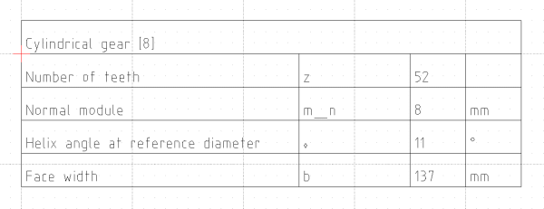
Exporting the gear stamp as .dxf
Output of the script
function writeTable(compID, path) {
    let dxf = new Dxf(getCompProperty(compID,'NAME'));
    let fontsize = 14;
    let lineHeight = 30;
    let start_x = 0;
    let start_y = lineHeight;
    let column_width = [340, 80, 80, 50];

    let tablewidth = column_width.reduce(function(a, b){return a + b;}, 0);
    let text_offset_x = 5;
    let text_offset_y = -5;

    dxf.setFontSize(fontsize);
    dxf.setLineWidth(1.0);
    dxf.drawRect(start_x, 0-lineHeight, tablewidth, start_y);
    dxf.drawString(getCompProperty(compID,'NAME'), start_x+text_offset_x, start_y+text_offset_y-lineHeight);
    let tableAttributes = [
                        "number of teeth",
                        "normal module",
                        "helix angle reference diameter",
                        "normal_pressure_angle",
                        "addendum modification coefficient",
                        "face width",
                        "standard pitch diameter",
                        "tip diameter",
                        "form diameter of addendum",
                        "root diameter",
                        "form diameter of dedendum",
                        "resulting number of teeth for span measurement finished teeth",
                        "span_measurement_upper_deviation",
                        "span_measurement_lower_deviation",
                        "iso_1328_2013_quality_grade_internal",
                        "profile_slope_deviation_acc_to_table",
                        "helix_slope_deviation_acc_to_table",
                        "profile_slope_deviation_acc_to_table",
                        "single_pitch_deviation_acc_to_table",
                        "total_cumulative_pitch_deviation_acc_to_table",
                        "runout_deviation_acc_to_table"
                        ];
    let tablecontent = [];
    for(let i=0; i<=tableAttributes.length-1; i++){
        tablecontent[i] = [];
        tablecontent [i][0]= getAttrProperty(tableAttributes[i], compID, 'NAME');
        tablecontent [i][1]= getAttrProperty(tableAttributes[i], compID, 'SYMBOL');
        tablecontent [i][2]= Math.round(getAttr(tableAttributes[i], compID, RDAT)*1e3)/1e3;
        tablecontent [i][3]= getAttrProperty(tableAttributes[i], compID, 'UNIT_NAME');
    }
    for(let i=0; i<=tablecontent.length-1; i++){
        for(let j=0; j<=column_width.length-1; j++){
            dxf.drawRect(start_x, 0, column_width[j], start_y);
            dxf.drawString(tablecontent[i][j], start_x+text_offset_x, start_y+text_offset_y);
            start_x = start_x+column_width[j];
        }
        start_y = start_y+lineHeight;
        start_x = 0;
    }
    let final_path = path+"\\"+getCompProperty(compID,'NAME')+"_gear_stamp.dxf";
    dxf.export(final_path);
    println(final_path);
}
path = promptDirectory();
var compIDs = getCompByType("cylindrical_gear");
println("The following files were exported:");

compIDs.forEach(function(element){
    writeTable(element, path);
});