Cylindrical gear load carrying capacity
Standard load carrying capacity calculations
Standard load capacity calculations include the combined knowledge and experience of industry and research. They have been successfully applied in gear development for decades, and have been exhaustively validated.
These global methods use relatively simple formulas to determine comparative values; e.g., stresses, temperatures, and lubricating film thicknesses, which can be compared against permissible limit values.
To obtain reliable results, it is important that the manufacturing, materials, and the system and operating conditions are known as well as the geometric design of the gears. The more familiar you are with these specifications, the fewer the safeguards that need to be maintained, allowing for lighter, smaller, and more cost-effective gears.
Globally, there are a number of standard load capacity calculations for cylindrical gears. The most important international standard is surely ISO 6336. The latest edition was published at the end of 2019 and has been extensively revised. Additional important standards include DIN 3990 and AGMA 2101 D04.
In the FVA-Workbench, these calculations can be performed for the entire system as well as for individual stages. Standard calculations according to DIN, ISO, and AGMA can all be performed simultaneously.
ISO 6336 (International Organization for Standardization)
The International Organization for Standardization (ISO) is an international association of standards organizations (e.g.; DIN, ANSI, etc.). There are currently 164 countries represented in the ISO (121 full members, 39 corresponding members, and 4 observers).
There are 249 different Technical Committees (TC). TC 60 is focused on gears, and Sub Committee (SC) 2 deals with gear capacity calculation. Working Group (WG) 6 is concerned with gear calculations, including the cylindrical gears of ISO 6336 (ISO/TC 60/SC 2/WG 6 ).
For more information, refer to the ISO website at: https://www.iso.org.
Generally speaking, the application of standards is voluntary; standards are non-binding. Standards become legally binding when laws or legal regulations, such as EU directives, refer to them. Contractual partners may also specify the application of standards in their agreements.
ISO 6336:2019-11 "Calculation of load capacity of spur and helical gears" consists of the following parts:
Part 1: | Basic principles, introduction and general influence factors (replaces ISO 6336-1 Technical Corrigendum 1:2008-06, ISO 6336-1:2006-09) | ISO 6336-1:2019-11 |
Part 2: | Calculation of surface durability (pitting) (replaces ISO 6336-2 Technical Corrigendum 1:2008-06, ISO 6336-2:2006-09) | ISO 6336-2:2019-11 |
Part 3: | Calculation of tooth bending strength (replaces ISO 6336-3 Technical Corrigendum 1:2008-06, ISO 6336-3:2006-09) | ISO 6336-3:2019-11 |
Part 4: | Calculation of tooth flank fracture load capacity | ISO/TS 6336-4:2019-01 |
Part 5: | Strength and quality of materials | ISO 6336-5:2016-08 |
Part 6: | Calculation of service life under variable load (replaces ISO 6336-6 Technical Corrigendum 1:2007-08, ISO 6336-6:2006-08) | ISO 6336-6:2019-11 |
Part 20: | Calculation of scuffing load capacity - Flash temperature method (replaces ISO/TR 13989-1:2000-03) | ISO/TS 6336-20:2017-11 |
Part 21: | Calculation of scuffing load capacity - Integral temperature method (replaces ISO/TR 13989-2:2000-03) | ISO/TS 6336-21:2017-11 |
Part 22: | Calculation of micropitting load capacity (replaces ISO/TR 15144-1:2014-09) | ISO/TS 6336-22:2018-08 |
Part 30: | Calculation examples for the application of ISO 6336 parts 1,2,3,5 | ISO/TR 6336-30:2017-11 |
Part 31: | Calculation examples of micropitting load capacity (replaces ISO/TR 15144-2:2014-10) | ISO/TR 6336-31:2018-09 |
ISO/TR – These "technical reports" contain purely informative data, e.g. example calculations.
ISO/TS – These "technical specifications" include calculation methods which are planned to be further developed and are intended to become a full-fledged standard.
ISO – These international standards include calculation methods that are based on widely accepted practices and have been extensively validated.
In the FVA-Workbench, ISO 6336 calculations can be performed for the entire system as well as individual components. Parts 1, 2, 3, and 6 make up the main part of the ISO. The following additional calculations can also be activated:
ISO 13691 - application standard for the petroleum and natural gas industries
DIN 3990 Part 4 - scuffing load capacity
ISO/TS 6336-20/-21:2017 - scuffing load capacity
FVA 166 - scuffing load capacity
FVA 54 - micropitting load capacity
IEC 61400-4:2012 - wind turbine gearboxes
ISO 6336-22 Calculation of micropitting load capacity
Calculation of the micropitting load capacity according to ISO/TS 6336-22:2018 supersedes the previous document, ISO/TR 15144-1:2014.The calculation method has been upgraded and integrated into the main ISO 6336 standard. The method was previously a technical report, a purely informative document. It is now a technical specification, meaning that the method is intended to be revised and transitioned into a complete standard.
Micropitting is fatigue damage on the contact surface of the mesh. It is a result of mixed friction due to an insufficient lubricating film thickness and the resulting breakdown of the surface. Visually, the damage can be identified by dull gray horizontal streaks across the face width. Under an electron microscope, a characteristic surface pattern can be recognized. With increasing operating time, material is removed from the area between the mesh and the pitch circle, similar to wear. The resulting profile form variation generally leads to increased meshing noise. Micropitting does not directly lead to gear failure, but it is often the beginning of consequential damage such as pitting.
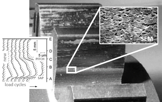 |
Figure: micropitting
This method calculates the safety against micropitting. To do so, the minimum specific lubricating film thickness on the path of contact is divided by the permissible specific lubricating film thickness.
Symbol | Description | Unit |
Sλ | Safety against micropitting | - |
λGF,min | Minimum specific lubricating film thickness on the path of contact | - |
λGFP | Permissible specific lubricating film thickness | - |
Sλ,min | Minimum required safety against micropitting | - |
Formula | Description | Unit |
λGF,Y | Local specific lubricating film thickness on the path of contact at point Y | - |
hY | Local lubricating film thickness at point Y | µm |
ρn,Y | Normal radius of relative curvature at point Y | mm |
GM | Material factor, considers the influence of temperature on the modulus of elasticity and pressure-viscosity coefficient. | - |
UY | Local velocity factor, describes the proportional increase of the specific lubricating film thickness with increasing dynamic viscosity of the lubricant at bulk temperature and the sum of the tangential velocities | - |
WY | Local load factor, calculated from the local Hertzian contact pressure, taking the local factors and reduced modulus of elasticity into consideration | - |
SGF,Y | Local sliding factor, considers the influence of the local sliding on the local temperature. This temperature influences both the local pressure-viscosity coefficient and the local dynamic viscosity, and thus the local lubricating film thickness. The local contact temperature is the sum of the local flash temperature and the bulk temperature. | - |
Ra | Effective arithmetic mean roughness value | µm |
Ra1/2 | Arithmetic mean of the roughness value of the pinion/wheel | µm |
The permissible specific lubricating film thickness can be determined using the methods from Annex A or B. The appendices, however, are purely informative and supportive, and are not part of the calculation method. Reference values are strongly recommended. Both annexes are only valid for mineral oils.
The calculation method in ISO/TS 6336-22:2018 is only valid for external cylindrical gears. The method can also be used for internal cylindrical gears, such as planetary stages, but the results do not deliver reliable values and should be used for informational purposes only.
For more details on the calculation, refer to ISO/TS 6336-22:2018.
Only a few specifications are needed to complete the calculation according to ISO/TS 6336-22:2018.
The ISO 6336 calculation method must first be activated in the FVA-Workbench, the micropitting calculation can then be enabled under the ISO 6336 tab.
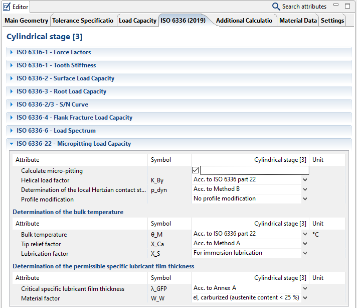 |
Figure: The input attributes in the Editor have been reduced to a minimum. A detailed description of the individual attributes is available in the Attribute Help. The Attribute Help briefly describes the parameters and explains the input and selection options.
Calculation of the force factors is defined in the general section of ISO 6336-1. Only the helix angle factor is directly related to the micropitting calculation; therefore, it is also specified there.
In most cases, the calculation can be performed with the default settings.
The following points should be reviewed and adjusted if necessary:
Profile modification: The type and quality of the profile modification must be specified. For example, the user must decide whether the profile at the tip of the gear has been sufficiently corrected. This setting has a decisive influence on the load distribution, and thus on the contact pressure distribution and the lubricating film thickness over the path of contact.
Lubrication factor: The type of lubrication influences the bulk temperature of the gear, and therefore the local contact temperature, the lubricating and the material, and thus the lubricant film thickness.
Specific reference film thickness: The permissible minimum lubricating film thickness directly influences the safety against micropitting. Calculation according to Annex A and B is only valid for mineral oils and should be used with caution, as the properties of mineral oils can be significantly influenced by additives at any time. Therefore, reference tests are recommended to determine the minimum permissible lubricating film thickness for the specific application.
DIN 3990 (German Institute for Standardization)
DIN 3990 (1987) is the series of standards on the load capacity of cylindrical gears from the German Institute for Standardization (Deutsches Institut für Normung, DIN). The ISO 6336 (2006) series of standards is based on this standard. The DIN standard is currently being revised and updated. The new version will primarily be based on the new ISO 6336:2019-11.
In the FVA-Workbench, DIN 3990 calculations can be performed for the entire system or individual components. DIN consists of the following main parts:
DIN 3990-1: Introduction and general influence factors
DIN 3990-2: Calculation of pitting resistance
DIN 3990-3: Calculation of tooth strength
DIN 3990-4: Calculation of scuffing load capacity
The following additional calculations can also be activated:
FVA 54 - micropitting load capacity
FVA 166 - scuffing load capacity
Plewe (1980) - wear calculation
AGMA 2101 D04 (American Gear Manufacturers Association)
AGMA 2101 D04 is the American Gear Manufacturers Association (AGMA) series of standards for cylindrical gear design. The main standard is focused on gear tooth fracture and pitting damage. The following additional calculations can also be activated:
AGMA 6011 (I06) - Specification for High Speed Helical Gear Units
AGMA 6113 (A06) - Standard for Industrial Enclosed Gear Drives (Metric Edition)
AGMA 6114 (A06) - Gear Power Rating for Cylindrical Shell and Trunnion Supported Equipment (Metric Edition)
AGMA 925 (A03) - Effect of Lubrication on Gear Surface Distress
API 613 5th edition (February 2003) - Special Purpose Gear Units for Petroleum, Chemical, and Gas Industry Services
API 617 7th edition (July 2002) - Axial and Centrifugal Compressors and Expander-compressors
VDI 2736 (Association of German Engineers)
VDI 2736 Blatt 2 (2014) was issued by The Association of German Engineers (Verein Deutscher Ingenieure, VDI). It focuses on the calculation of the load-carrying capacity of thermoplastic gear wheels.
Old methods
In addition to the international and locally-recognized load capacity methods, there are many other local methods from different countries.
In the FVA-Workbench, the following three methods from older versions can still be used for calculations:
Load capacity according to BS 436 (1940)
This standard from the British Standards Institution (BSi) is entitled "Specification for machine cut gears. A. Helical and straight spur,“ and has been replaced by BS 436-1:1967, BS 436-2:1970, BS 436-3:1986.
Load capacity according to Niemann (1965)
Load capacity according to Henriot (1976)
Classification societies
Verification of the load capacity according to classification societies plays an important role for manufacturers of marine gear units and gears for the offshore industry. Most nations do not allow non-classified ships in their territorial waters.
There are currently twelve internationally recognized classification societies, which are grouped together under the umbrella organization International Association of Classification Societies (IACS). They all have different rulesets which must be complied with for classification.
The calculation of the load capacity for cylindrical gears is based on the International Organization for Standardization (ISO) standard with the designation ISO 6336 "calculation of load capacity of spur and helical gears." Until November 2019, ISO 6336 (2006) only covered the pitting and flank fracture forms of damage.
Classification society calculation guidelines are continually updated to include the latest findings from research and practice.
The recent publication of ISO 6336 in November 2019 means that an update to the classification society regulations is inevitable. Therefore, revised regulations should be expected in the next few years.
To facilitate recalculation for existing gears, it is still possible to perform calculations according to older and obsolete methods in the FVA-Workbench. For example, this may be necessary in the case of damage.
These calculations can only be performed for cylindrical gear stages, not the entire system. The influence of a complex system calculation with the resulting misalignment of the gear mesh and the effects of the microgeometry results in the face load factor KHβ. Once this has been determined, it can be specified for the single component calculation, thereby taking the behavior of the system into account.
The following classification societies are available in the FVA-Workbench:
American Bureau of Shipping (ABS), USA
The current ABS guideline "Rules for Building and Classing Steel Vessels" dates from 2019. Older ABS calculation methods from 1980, 2004, and 2011 are also still available in the FVA-Workbench.
The corresponding documents are available for download free of charge from the ABS homepage at https://ww2.eagle.org/.
The relevant section for cylindrical gears is Part 4, Chapter 3 "Propulsion and Maneuvering Machinery," Section 1, Appendix 1 "Rating of Cylindrical and Bevel Gears."
Basis of the ABS 2019 Calculation
Similar to ISO 6336, the following points are described in the standard:
Symbol | Description |
|---|---|
KA | The application factor KA accounts for dynamic overloads from sources external to the gearing. The application factor, for gears designed for infinite life is defined as the ratio between the maximum repetitive cyclic torque applied to the gear set and the nominal rated torque. The additional forces mainly depend on the characteristics of driving and driven machines, the masses and stiffnesses in the input and output trains (e.g. shafts and couplings), and the operating conditions. |
Kγ | The load sharing factor Kγ accounts for the maldistribution of load in multiple-path transmissions; e.g., dual tandem, epicyclical, double helix. It is defined as the ratio between the maximum load through an actual path and the evenly shared load. The factor mainly depends on the accuracy and flexibility of the branches |
Kv | The dynamic factor Kv accounts for internally generated dynamic loads due to vibrations of the pinion and wheel against each other. The dynamic factor is defined as the ratio between the dynamic maximum force of a gear pair in mesh to the corresponding toothing forces of the same gear pair at a speed close to zero. |
KHβ, KFβ | The face load distribution factors KHβ for contact stress and KFβ for tooth root bending stress account for the effects of non-uniform load distribution across the face width. The factors are defined as the ratio of the maximum load per unit face width to the mean load per unit face width. |
KHα, KFα | The transverse load distribution factors KHα for contact stress and KFα for tooth root bending stress account for the effects of pitch and profile errors on the transverse load distribution between two or more pairs of teeth in mesh. The factors are defined as the ratio between the maximum force of a gear pair in mesh at a speed close to zero to the corresponding toothing forces of a deviation-free gear pair. |
The criterion for surface durability is based on the Hertzian pressure on the operating pitch point or at the inner point of single pair contact. The contact stress σH is not to exceed the permissible contact stress σHP.
Contact stress σH
Symbol | Description | Unit |
|---|---|---|
σH | Contact stress, for pinion and wheel in critical single pair contact | N/mm2 |
σH0 | Basic value for contact stress at operating pitch point, the load on an error-free gear from the static rated torque, to be calculated separately for pinion and wheel | N/mm2 |
σHP | Permissible contact stress, to be calculated separately for pinion and wheel | N/mm2 |
ZB | Single pair mesh factor for pinion, transforms the contact stresses determined at the pitch point to contact stresses considering the flank curvature at the inner point of single pair contact. | - |
ZD | Single pair mesh factor for wheel, transforms the contact stresses determined at the pitch point to contact stresses considering the flank curvature at the inner point of single pair contact. | - |
ZH | Zone factor, accounts for the influence on the Hertzian pressure of tooth flank curvature at pitch point and relates the tangential force at the reference cylinder to the normal force at the pitch cylinder | - |
ZE | Elasticity factor, accounts for the influence of the material properties modulus of elasticity and Poisson’s ratio | - |
Zε | Contact ratio factor, accounts for the influence of the transverse contact ratio and the overlap ratio | - |
Zβ | Helix angle factor, accounts for the influence of helix angle | - |
Ft | Nominal transverse tangential load | N |
b | Common face width | mm |
d1 | Reference diameter of pinion | mm |
u | Gear ratio = z2 / z1 | - |
Permissible contact stress σHP
Symbol | Description | Unit |
|---|---|---|
σHP | Permissible contact stress, to be calculated separately for pinion and wheel | N/mm2 |
σHlim | Endurance limit for contact stress, accounts for the influence of the material, heat treatment, and surface of the standard reference test gear | N/mm2 |
SHmin | Required minimum safety factor for contact stress | - |
ZN | Life factor for contact stress, accounts for the higher permissible contact stress, including static stress, in case of a limited number of load cycles | - |
ZL | Lubricant factor, accounts for the influence of the type of lubricant and its viscosity | - |
ZV | Speed factor, accounts for the influence of the pitch line velocity | - |
ZR | Roughness factor, accounts for the influence of the surface roughness | - |
ZW | Hardness ratio factor, accounts for the increase of surface durability of a soft steel gear when meshing with a surface hardened gear with a smooth surface | - |
ZX | Size factor, accounts for the influence of tooth dimensions on permissible contact stress | - |
If the gear is connected to the shaft by an interference fit, the permissible contact stress σHP is calculated by multiplying the factor KS by the contact stress σ H.
Symbol | Description | Unit |
|---|---|---|
KS | Safety factor available for induced contact stresses | - |
δmax | Maximum available interference fit or maximum pull-up length | mm |
dri | Inner diameter of wheel rim | mm |
dw | Working pitch diameter of wheel | mm |
mn | Normal module | mm |
ρF | Root fillet radius in the critical section | mm |
Y | Yield strength of wheel rim material | N/mm2 |
The criterion for tooth root bending strength is the permissible limit of local tensile strength in the root fillet. The tooth root stress σF and the permissible tooth root stress σFP are to be calculated separately for the pinion and the wheel, whereby σF is not to exceed the permissible tooth root stress σFP.
Tooth root stress σF
Symbol | Description | Unit |
|---|---|---|
σF | Tooth root stress, for pinion and wheel in critical single pair contact | N/mm² |
σF0 | Nominal tooth root stress, the maximum local tensile stress on an error-free gear from the static rated torque, to be calculated separately for pinion and wheel | N/mm² |
σFP | Permissible tooth root stress, to be calculated separately for pinion and wheel | N/mm² |
YF | Tooth form factor, represents the influence on nominal bending stress of the tooth form with load applied at the outer point of single pair tooth contact | - |
YS | Stress correction factor converts the nominal bending stress to the local tooth root stress. Thereby, it includes the stress-increasing effect of the notch (fillet) and the fact that a complex stress state exists in the critical cross-section the root. | - |
Yβ | Helix angle factor, converts the stress calculated for a point loaded cantilever beam representing the substitute gear tooth to the stress induced by a load along an oblique load line into a cantilever plate which represents a helical gear tooth. | - |
Ft | Nominal transverse tangential load at reference cylinder | N |
b | Face width | mm |
mn | Normal module | mm |
Permissible tooth root stress σFP
Symbol | Description | Unit |
|---|---|---|
σFP | Permissible tooth root stress, to be calculated separately for pinion and wheel | N/mm² |
σFE | Bending endurance limit, of the un-notched specimen, with the assumption that the material is fully elastic, including heat treatment. | N/mm² |
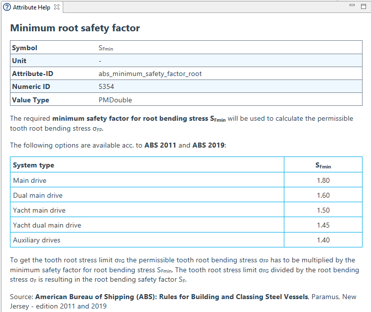
SFmin | Required minimum safety factor for tooth root bending stress | - |
Yd | Design factor, takes into account the influence of load reversing; i.e., for idler gears and gears with part load in reversed direction | - |
YN | Life factor, accounts for the higher permissible tooth root bending stress in case of a limited life (number of load cycles) | - |
YδrelT | Relative notch sensitivity factor, considers the influence of the notch sensitivity of the material | - |
YRrelT | Relative surface factor, takes into account the dependence of the tooth root bending strength on the surface condition in the tooth root fillet | - |
YX | Size factor (root), takes into account the decrease of the strength with increasing size | - |
Only a few attributes need to be specified for successful calculation according to ABS.
Input options
The input options for ABS 2019 are comparable to ABS 2011. Only a few points have been changed or expanded.
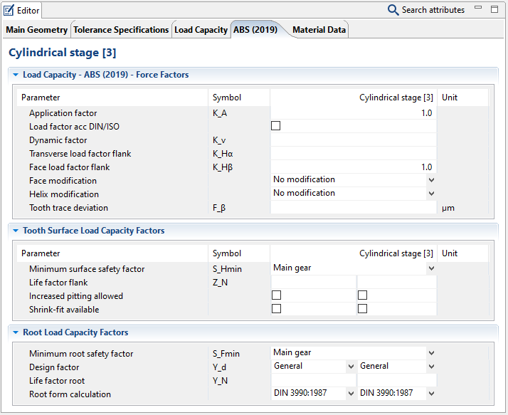
The ABS input attributes in the Editor are divided into three sections. A detailed description of the individual attributes is available in the Attribute Help. The Attribute Help briefly describes the parameters and explains the available input or selection options.
Force factors
These describe general external influences and system behavior. The factors are usually either directly specified or calculated according to the ABS rules or ISO6336.
Flank load capacity
Here, the critical point is the required minimum safety against pitting damage, which must be specified according to the application. The life factor, increased pitting, or an interference fit can optionally be defined to determine the permissible contact stress.
Tooth root bending strength
The required minimum safety against flank fracture must be specified according to the specific application. The design factor and life factor must be defined for calculation of the permissible tooth root stress. The root form geometry is decisive for calculation of the tooth root strength. According to ABS 2019, it is calculated as in DIN3990:1987. Optionally, the dedendum can also be calculated according to ISO6336:2006 and ISO6336:2019.
Bureau Veritas (BV), France
The latest version of the BV "Rules for the classification of steel ships" in the FVA-Workbench dates from 2010. In the FVA-Workbench, calculations can also still be performed according to BV rules from 1977 and 2003/2006.
The current rules can be downloaded for free from the BV homepage at https://www.bureauveritas.de/.
The relevant section for cylindrical gears is Part C "Machinery, Electricity, Automation, and Fire Protection," Chapter 1 "Machinery," Section 6 "Gearing."
A revised set of rules was published in January 2020; however, this has not yet been implemented in the FVA-Workbench. One particular feature of this version is that it also includes calculation of the scuffing load capacity according to the flash temperature method.
China Classification Society (CCS), China
The latest CCS "Rules for classification of sea-going steel ships" in the FVA-Workbench dates to 1996.
The relevant section for cylindrical gears is Part 3, Chapter 10 "Transmission gearing," Appendix 1 "Appraisal of gear strength."
The current rules can be downloaded free of charge from the CCS homepage at https://www.ccs.org.cn/.
Det Norske Veritas (DNV), Norway
DNV merged with Germanischer Lloyd (GL) from Germany in 2013. Therefore, there are no updated DNV rulebooks since this date.
The most recent DNV "Calculation of Gear Rating for Marine Transmissions N.41.2“ in the FVA-Workbench is from 2012. In the FVA-Workbench, calculations can also still be performed according to DNV rules from 1978, 1990/1993, and 2003.
One particular feature of this version is that it also includes calculation of the scuffing load capacity according to the flash temperature method.
The current rules can be downloaded for free from the DNV-GL homepage at https://www.dnvgl.de/.
Germanischer Lloyd (GL), Germany
GL merged with Det Norske Veritas (DNV) from Norway in 2013. Therefore, there are no updated GL rulebooks since this date.
The most recent GL "Rules for Classification and Construction - Ship Technology" in the FVA-Workbench is from 1998/2006. In the FVA-Workbench, calculations can also still be performed according to an older GL method from 1980.
The relevant section for cylindrical gears is Part 1 "Seagoing Ships," Chapter 2 "Machinery Installations," Section 5 "Gears, Couplings."
The current rules can be downloaded for free from the DNV-GL homepage at https://www.dnvgl.de/ .
Lloyd's Register of Shipping (LRS), England
The latest LRS "Rules and Regulations for the Classification of Ships" in the FVA-Workbench is from 2019. In the FVA-Workbench, calculations can also be performed according to LRS methods from 1978 and 1990/2006.
The relevant section for cylindrical gears is Part 5 "Main and Auxiliary Machinery," Chapter 5, "Gearing," Section 3, "Design."
The current rules can be downloaded free of charge from the LRS homepage at https://www.lr.org/.
Registro Italiano Navale (RINA), Italy
The current version of the RINA "Rules for the classification of ships" in the FVA-Workbench is from 2004/2006. In the FVA-Workbench, calculations can also still be performed according to an older RINA method from 1982.
The relevant section for cylindrical gears is Part C "Machinery, Systems and Fire Protection," Chapter 1 "Machinery," Section 6 "Gearing."
The current rules can be downloaded free of charge from the RINA homepage at https://www.rina.org/.
Russian Maritime Register of Shipping (RMS), Russia
The current version of the RMS "Rules for the Classification and Construction of Sea-Going Ships" in the FVA-Workbench is from 2005/2020.
The relevant section for cylindrical gears is Part IX "Machinery," Chapter 4 "Gears, disengaging and elastic couplings," Section 2 "Gearing."
The current rules can be downloaded free of charge from the RMS homepage at https://rs-class.org/.