Virtual FVA Gear Unit
The Virtual FVA Gear Unit was conceived as a fictional example to demonstrate the gear calculation capabilities of various FVA programs.
Historical FVA report (1988) published in Antriebstechnik Nr. 7 (in German)
Modeling the drive stage
Create a new model
 (Project → New).
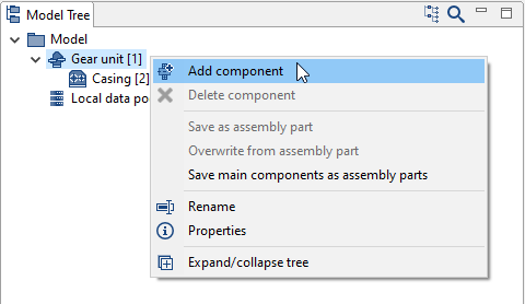
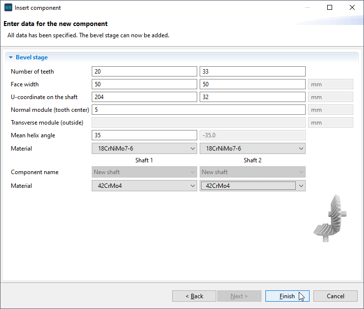
Enter the gear data
Specify the data for the gear and material as shown in the image below. New shafts will automatically be created for the bevel pinion and bevel gear.
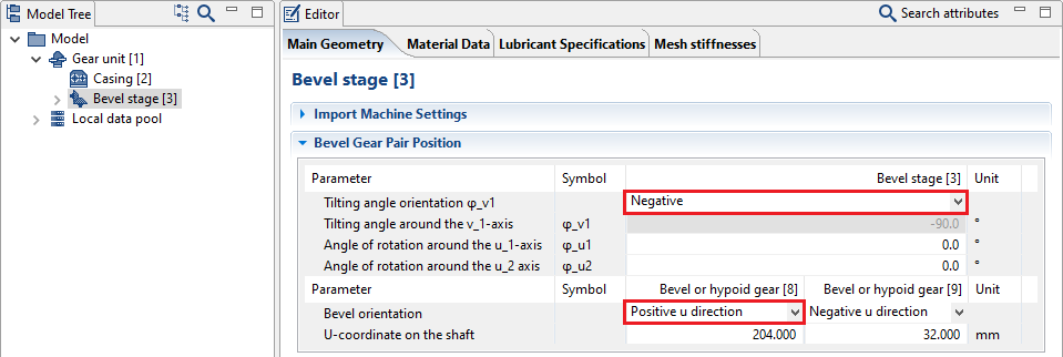
Change the orientation of the bevel gear stage
Select the bevel gear stage in the Model Tree and go to the "main geometry" tab in the Editor. Enter the orientation of the tilt angle and the bevel cone tip as shown.
Import the Standard.KGD file
The geometry data for the bevel gear will automatically be completed following the import. The Standard.KGD is an input interface for the calculation of bevel gears and includes all necessary information for the manufacturing simulation and generating the nominal geometry.
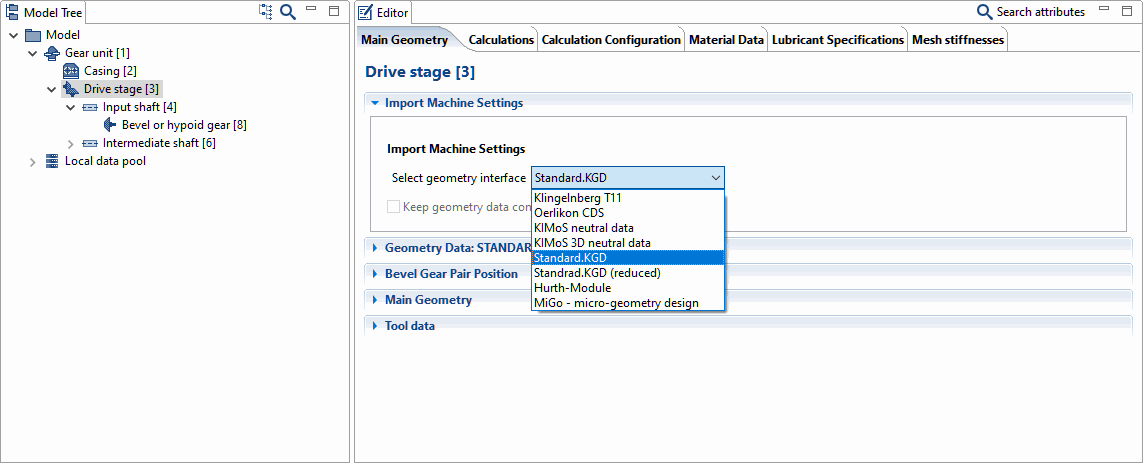
Download the Standard.KGD file and select the corresponding entry for the machine settings in the drop-down menu. Now, specify the path to the Standard.KGD file.
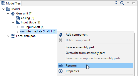
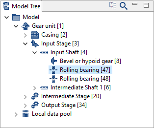
Rename the components
It is helpful to assign unique names to the components in the Model Tree, especially for complex models. Right-click on the component in the Model Tree and choose rename (or use F2):
Bevel gear stage [3] → Drive stage [3]
Shaft [4] → Drive shaft [4]
Shaft [6] → Intermediate shaft 1 [6]
Specify the contours of the drive shaft
Select the drive shaft in the Model Tree and go to the "shaft contour" tab in the Editor. The inner and outer contours as well as the axial starting coordinate of the shaft can be specified here. Click
 to add two shaft sections. Enter the length and diameters of the sections as shown below.
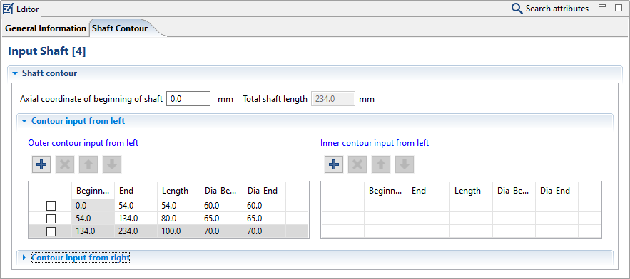
Notice
The starting value of the shaft contour is determined from the geometry and cannot be specified.
Specify the contours of the intermediate shaft
Perform the same steps for the intermediate shaft.
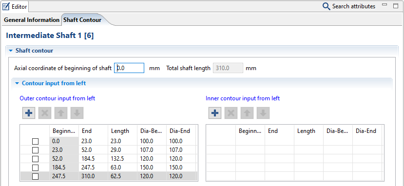
Notice
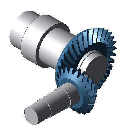
Use the schematic view  and cutting plane in the 3D view
  to check your entries while modeling the shaft.
Modeling the intermediate stage
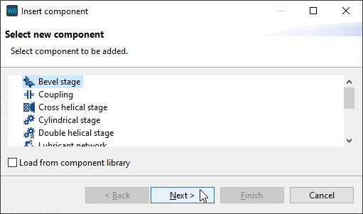
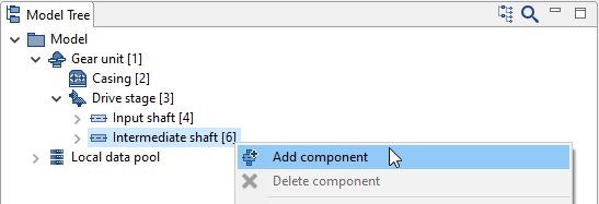
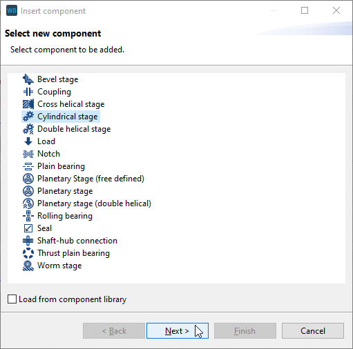
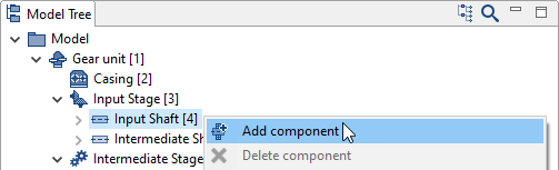
Add a cylindrical gear
Right-click on intermediate shaft 1 [6] in the Model Tree and add a new cylindrical stage component.
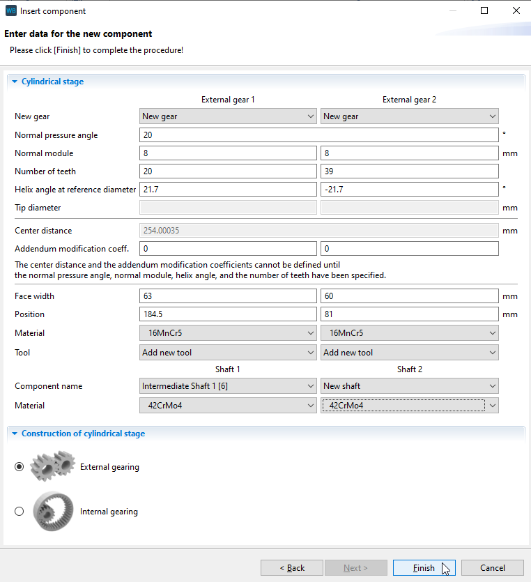
Specify the gear data
Enter the gear data in the stage wizard as shown in the image below. The first cylindrical gear will now be added to intermediate shaft 1 [6]. The second cylindrical gear of the stage will be added to the model along with a new shaft.
Rename the components
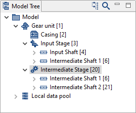
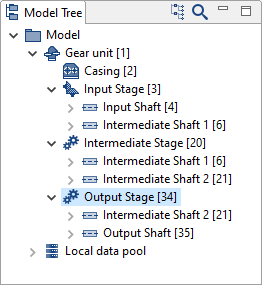
The intermediate stage, consisting of intermediate shaft 1, intermediate shaft 2, and two helical gears will be added. Rename the new components to:
Cylindrical stage [20] → Intermediate stage [20]
Shaft [21] → Intermediate shaft 2 [21]
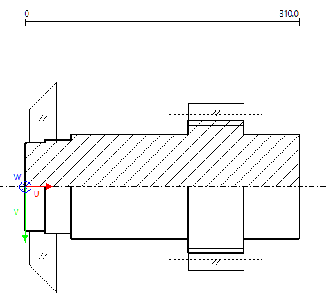
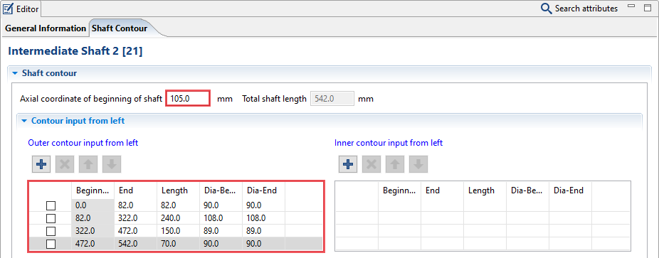
Model the contours of Intermediate Shaft 2
Add 3 new shaft sections in the "outer contour from left" field of the shaft contour editor. Enter the length and diameter for each section and change the starting coordinate of the shaft as shown.
Modeling the output stage
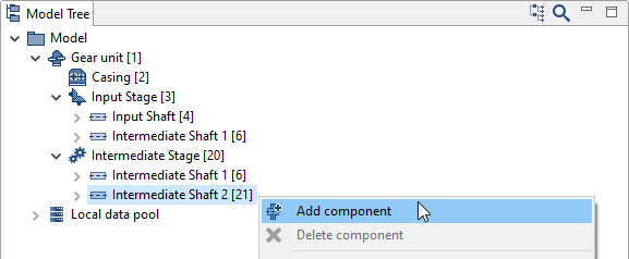
Add a cylindrical stage
The output stage should be added to intermediate shaft 2, which already exists. To do this, right-click on intermediate shaft 2 in the Model Tree and add a new cylindrical stage component.
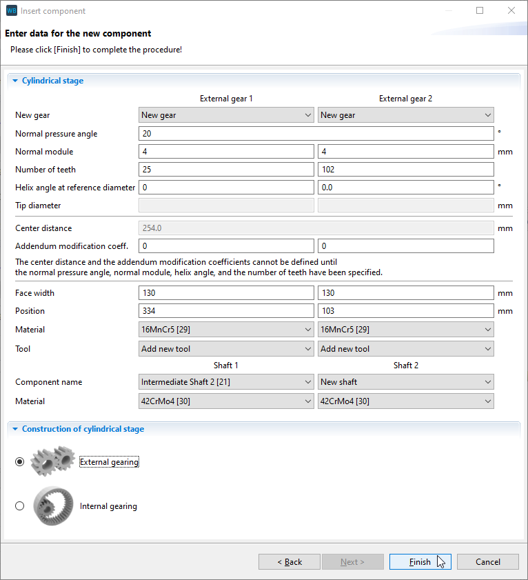
Specify the gear data
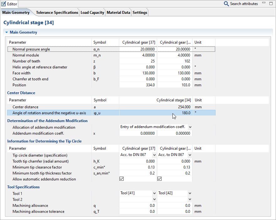
Enter the gear data in the cylindrical stage wizard according to the image below. The first gear will be added to intermediate shaft 2. The second gear of the stage will be added to the model along with a new shaft.
Change the angle of rotation about the negative u-axis
Select the output stage in the Model Tree and change the angle of rotation about the negative u-axis to 180° under the main geometry tab in the editor.
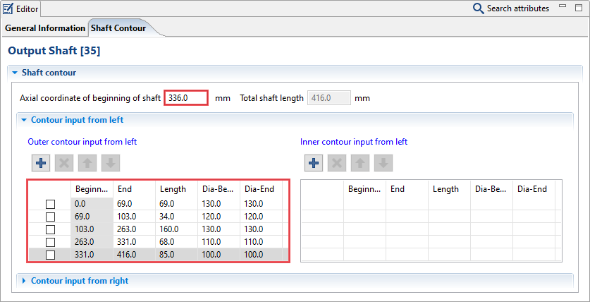
Specify the contours of the Output Shaft
Add 3 new shaft sections in the "outer contour input from left" field of the shaft contour editor. Enter the length and diameter for each section and change the starting coordinate of the shaft as shown below.
Adding the bearings
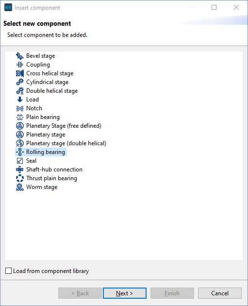
Add bearings
Add a rolling bearing on the drive shaft. To do so, right-click on the drive shaft and a rolling bearing component.
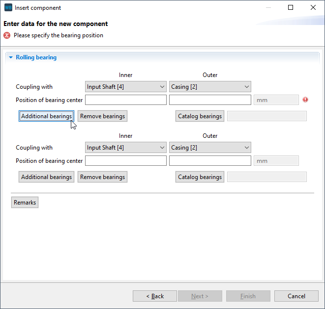
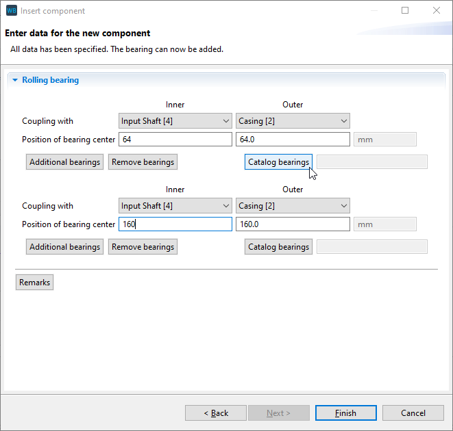
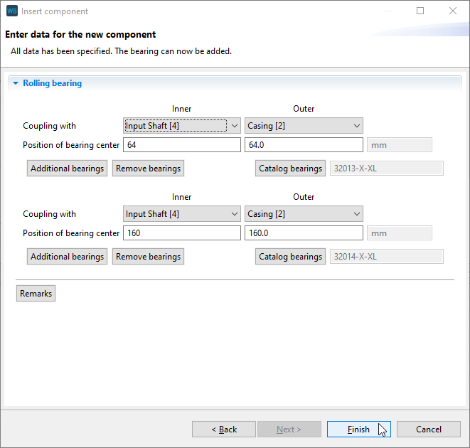
Specify the bearing position
Click on additional bearings to simultaneously add two rolling bearings on the shaft. Enter the positions of the inner rings as shown below. The position of the outer rings will be calculated automatically. Now, click catalog bearings to choose a bearing from the catalog.
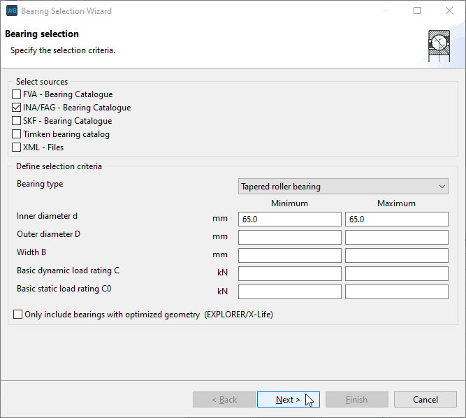
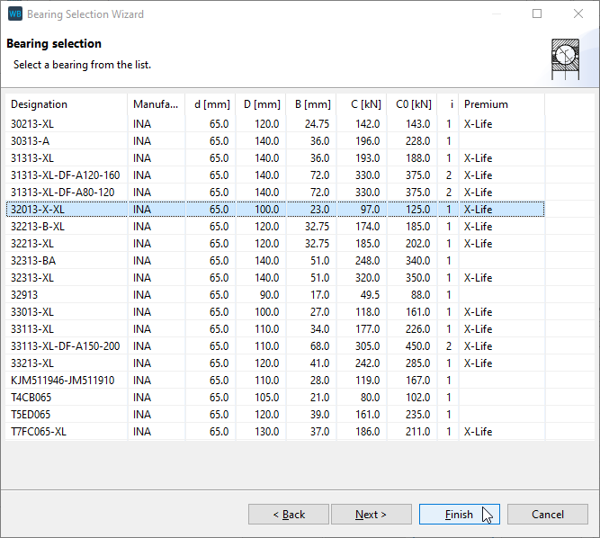
Bearing 1: select a catalog bearing
In the bearing selection assistant, choose tapered roller bearings as the bearing type and INA/FAG as the manufacturer. Select INA 32013-X-XL. Click next to show the bearing details or finish to select the bearing.
Bearing 2: select a catalog bearing
Select the catalog entry INA 32014-X-XL for the second bearing. Click "Finish"
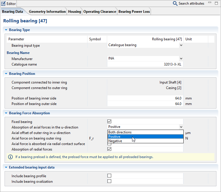
Specify the bearing arrangement
Choose an X arrangement for both bearings. Select the first bearing under the drive shaft in the Model Tree and set the "absorption of axial forces in the u-direction" in the Editor to positive. Set the second bearing accordingly to negative.
Add additional bearings
Add the other bearings on the shaft as with the INA 32013-X-XL tapered roller bearings.
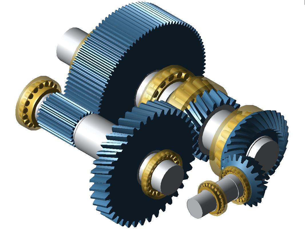 Table 111. Overview of the bearings in the model
Bearing name
Position of the inner ring [mm]
Direction
Arrangement
Drive shaft
INA 32013-X-XL tapered roller bearing
64
Positive
O
INA 32014-X-XL tapered roller bearing
160
Negative
Intermediate shaft 1
FVA 32224 J2 tapered roller bearing
80
Positive
O
FVA 32224 J2 tapered roller bearing
280
Negative
Intermediate shaft 2
INA 32018-X-XL tapered roller bearing
46
Negative
X
INA 33118-XL tapered roller bearing
502
Positive
Output shaft
SKF NU 1026ML cylindrical roller bearing
40
-
-
SKF NU 2222 ECP cylindrical roller bearing
291
-
Loads
Loads are added to a shaft as a component. This can be done by right-clicking on the shaft or centrally in the power flow editor.
Select the gear unit in the Model Tree and change to the power flow tab in the Editor. Click  to add load components on the shaft. Enter the power flow data according to the table.
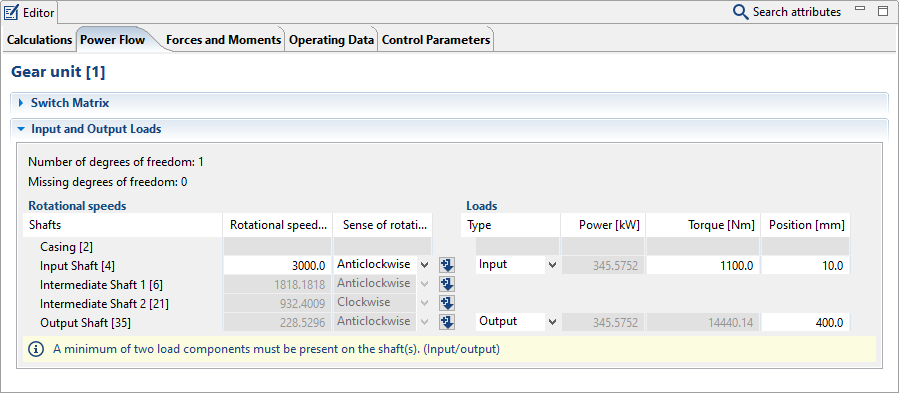
Drive shaft | Output shaft | |
|---|---|---|
Type of torque introduction | Drive | Output |
Torque | 1100 Nm | will be calculated |
Direction of rotation | left | will be calculated |
Speed | 3000 1/min | will be calculated |
Notice
Load components must be present on at least two shafts (drive/output) for a correct power flow.
For a load component, at least the
Direction of rotation
Speed
Power or torque
must be specified.
The type of torque introduction must be specified for both loads.
Operating data
Finally, operating data must be specified for at least the lubricant and oil temperature in order to be able to start the system calculation. Select the lubricant "ISO-VG-320" from the Global Database. Enter a lubricant temperature of 80°C.
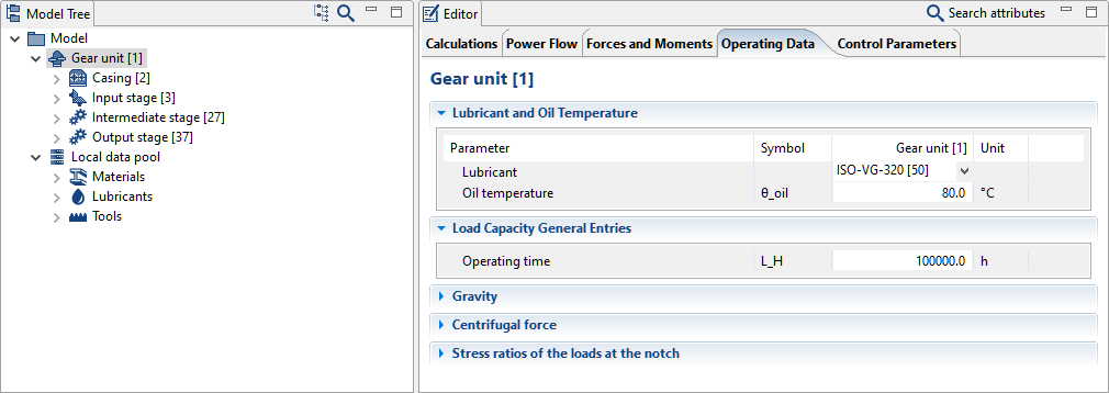
The lubricant used and its temperature can be specified under "operating data" for the gear unit component in the Editor.
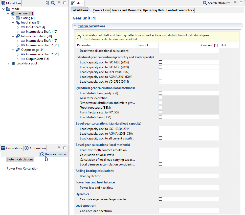
Calculation and results
Start a system calculation
Click run calculation to begin the system calculation. Additional calculations can be added in the Editor under the calculations tab.
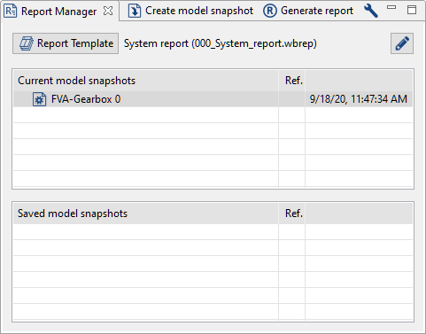
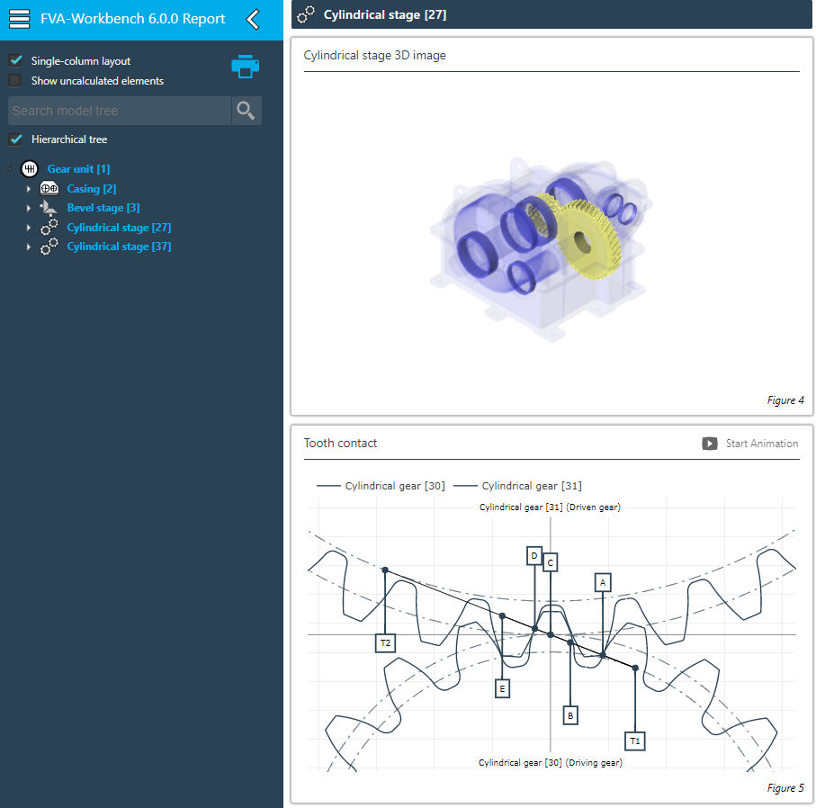
View the results report
After the calculation, a new model snapshot is created in the Report Manager. This includes all entries and calculation results as of the time of the calculation. Double-click on the model snapshot to generate a report.